 Xiaogang Chen1
 Aihong Tang
 Binyu Xiong
- 1State Grid Zhejiang Electric Power Co., Ltd., Hangzhou, China
- 2Automation School, Wuhan University of Technology, Wuhan, China
A distributed power flow controller (DPFC) can control the line power flow in a flexible and fast way to meet the requirements of a new power system. However, the output of DPFC sub-units is generally distributed by the even distribution method or proportional distribution method at present. The internal health status and output capacity of the device are not taken into account, which affects the efficiency and service life of the device. In this article, a reliability description method of DPFC based on fault probability is proposed. The coordination strategy of output voltage capability and the number of input sub-units is proposed, and the process of the proposed coordinated strategy for device output is presented. The simulation results show that the proposed coordinated output strategy can address the issue of rapid reliability decline caused by the long-term work of some sub-units and improve the overall reliability of the DPFC.
Introduction
Under the background of ‘dual carbon,’ China proposes the goal of building a new power system based on renewable energy. A large scale of renewable energy, such as wind and solar energy, will be connected to the transmission network or distribution network in a centralized or distributed manner. The volatility and intermittency nature of renewable energy output and the insufficient transmission capacity of lines may lead to overload and bidirectional power flow problems of transmission lines (Kang and Yao, 2017; Huang et al., 2019a; Zhang et al., 2022). At the same time, uncontrolled power flow will cause problems such as insufficient power supply in some regions, large transmission loss of lines, and even reduced stability and reliability of the system (Rashed et al., 2020; Liu et al., 2021).
Distributed power flow controller changes transmission line parameters by generating or absorbing reactive power so as to achieve flexible and fast line power flow regulation (Brissette et al., 2015; Shen et al., 2021; Song et al., 2022).
In 2019, in order to solve the problem of system congestion caused by the high penetration of renewable energy, IPTO of Greek transmission company installed a full control mode power flow regulator (hereafter referred to as DPFC in this article) (Gaigowal and Renge, 2016) developed by Smart Wires company in Peloponnesian, Greece. Inductance–capacitance smooth transition full control distributed power flow controller was successfully put into operation in Huzhou and Hangzhou in 2020, which is led by Zhejiang Electric Power Company, and participated by State Grid of China and NR Electric Company (Zhan et al., 2019).
The abovementioned engineering application results show that (Gaigowal and Renge, 2016; Zhan et al., 2019) the failure of a certain phase or a group of units of DSSC does not affect the operation of other units, and the overall reliability is much higher than that of the conventional centralized flexible AC transmission system(FACTS). However, hundreds of DPFC sub-units are installed along the overhead transmission line in groups, and in different phases, the operation environment is poor. The health status of a single sub-unit is easily affected, which affects the output capacity of the device, changes the normal dynamic response characteristics of the DPFC sub-unit, and directly affects the response characteristics and output capability of other DPFC sub-units through power line coupling. The health status of a single sub-unit has a great impact on the achievement of the expected goal of power flow regulation and restricts the speed of the popularization and application of DPFC.
Research studies on DPFC of references (Gaigowal and Renge, 2016; Ke et al., 2019; Guan et al., 2021; Xiong et al., 2022; Zhao et al., 2022) have adopted an even distribution method (all the sub-units in operation have equivalent output) and proportional distribution method (the output of each sub-unit is distributed proportionally by capacity) in the control strategy to distribute the output of each sub-unit in a centralized manner. In the study by Gaigowal and Renge (2016), a centralized management and optimal allocation scheme for DPFC is proposed, which completes the optimal allocation test of DPFC master unit based on RTDS. In the study by Guan et al. (2021), the impedance and power equivalent models of the DPFC system are proposed to analyze the relationship between voltage, impedance, and power of DPFC. In the study by Zhao et al. (2022), a real-time optimal allocation method for the output of DPFC sub-units based on centralized control is proposed, which is based on the idea of 'state classification - prioritized by regulation performance’. However, the optimization methods proposed in studies by Gaigowal and Renge (2016); Guan et al. (2021); and Zhao et al. (2022) are all in need of multiple rounds of debugging, the regulation speed is slow, and the priority of the sub-unit is only determined by the adjustable capacity of each unit, the DPFC will have a large overall operation loss when the regulation target is relatively small, for the sub-unit with large capacity will stay in operation for a long time and the sub-unit with small capacity will have a low utilization rate. The economic benefits and reliability of the device are low. In the study by Xiong et al. (2022), a cluster control strategy is proposed so that the distributed flexible AC transmission equipment can work stably with a high compensation efficiency in the whole operation range, but the difference in device capacity and device operation loss is not considered. By dispatching and configuring the available resources in a centralized control method, a switching control strategy for DPFC sub-unit is proposed by Ke et al. (2019), which can enrich the application scenarios of DPFC and enhance the application flexibility of DPFC, but it is essentially an even distribution method. When the even distribution method is used, if the capacity of the sub-unit is inconsistent, the utilization rate of the sub-unit with large capacity is low, and the economic effect is poor. The regulation range of the whole system is restricted by the sub-unit with the smallest capacity, and the sub-unit with a small capacity will be prone to overload and heat, which will bring damage to the health of DPFC. When the proportional distribution method is used, the output will be determined in proportion according to the capacity of each sub-unit. But if the regulation need is small, all the sub-units will be charged and put into operation, the overall utilization rate of the device is low, the device loss is large, and it also affects the health status of the device indirectly (Mao et al., 2017). In the study by Tang et al. (2022), the proposed optimal output power coordinated control strategy of DPFC considers the total loss of DPFC device. But it is based on the optimal algorithm, which leads to the high complexity of this method. Moreover, we can learn from the abovementioned literature that all the sub-units of DPFC are assumed to be healthy in the current even distribution method and proportional distribution method, and their output distribution is on the basis of the rated capacity of the device, which is defaulted to the maximum available of all the sub-units. However, as mentioned in the existing demonstration projects (Gaigowal and Renge, 2016; Zhan et al., 2019) and references (Liu et al., 2016; Qian et al., 2018; Elgebaly, 2019; Saeed et al., 2019), if the device is not in a healthy status, the maximum capacity of DPFC can be used will no longer be its rated capacity. It can be concluded that whether the proportional distribution method is adopted or the even distribution method is used, the sub-unit cannot operate as expected in the control so DPFC will fail to achieve the expected power flow control target, which affects the safe and stable operation of the power system.
In this article, a coordinated output control method considering the health status of the device is proposed to improve the utilization efficiency of the device capacity, reduce the device loss, and give full play to the economic and efficient power flow function of DPFC.
Basic principle
The primary equipment of DPFC sub-unit is a H-bridge voltage source converter consists of IGBT (Peddakapu et al., 2020). Its basic structure is shown is shown in Figure 1.
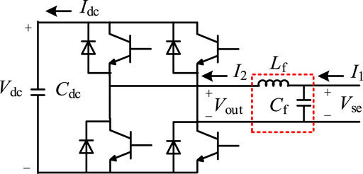
FIGURE 1. Basic structure of DPFC primary sub-unit equipment.
It is of note that
When filter link is included in the DPFC sub-unit, the following equations can be obtained according to the circuit equation of DPFC sub-unit:
When filter link is not configured in the DPFC sub-unit,
The whole DPFC system is composed of multiple DPFC sub-units. These sub-units are all connected to the power system in series. Each sub-unit can be viewed as a controllable voltage source. The equivalent model of the whole DPFC system in power system is shown in Figure 2.
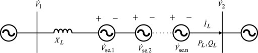
FIGURE 2. Equivalent controllable voltage source model of DPFC System.
In Figure 2,
It is of note that the injection voltage is the voltage injected into the line by DPFC sub-unit, the output voltage is voltage at the AC-side of the converter. In order to further analyze the impact of the injection voltage of the DPFC sub-unit on active power flow of the line, the active power flow is expressed in detail and rewritten as follows:
It can be obtained from Eq. 6 that if the active power flow reference value of DPFC system is determined, the line impedance parameters need to be compensated by DPFC system can be derived as follows:
where
The total voltage injected by all the DPFC sub-units in operation can be written as shown in Eq. 9:
Control for a single DPFC sub-unit is essentially the control of the output voltage of DPFC sub-unit. The DPFC sub-unit is acting on the line through the injection voltage
Considering that if the LC link is not included in the primary equipment of the DPFC sub-unit, the injection voltage will be the output voltage to be controlled. The control strategy can be simplified, as shown in Figure 3.
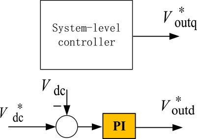
FIGURE 3. Simplified control strategy of DPFC sub-unit.
In the control strategy mentioned in Figure 3,
The system-level controller of DPFC consists of the calculation module, the mode control module (DPFC can work in several different modes (Lou et al., 2021)), and the output voltage distribution module. It is described in detail in Figure 4.
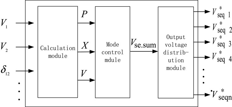
FIGURE 4. System-level controller diagram of DPFC.
It can be seen from Figure 4 that for DPFC working in all the modes, the output distribution of DPFC sub-units concentrates on the q-axis component of the output voltage, and that is the output of the output voltage distribution module. So, in the following, the distribution method for the q-axis component of the output voltage will be mainly analyzed to realize the optimal output distribution of multiple DPFC sub-units.
Output distribution method of DPFC
When the even distribution method is adopted for the output of DPFC, if the output voltage need is small, the actual output of each sub-unit is very small, and the utilization rate of the DC voltage is low (which means a low modulation ratio). When the converter used in DPFC is a voltage source converter, if the modulation ratio is very low, there will be a large proportion of harmonics in the output voltage, the waveform distortion of the output voltage will be serious, and the device efficiency will not be high. Therefore, in order to improve the working efficiency of each DPFC sub-unit, it is better to ensure that the output voltage of each DPFC sub-unit is higher than 80% of the rated voltage.
At the same time, before selecting the DPFC sub-unit to operate, if the sub-unit with high reliability are selected as the power flow controller to track the reference, the reliability of the whole system will be greatly improved (Huang et al., 2019b; Chen et al., 2019; Huang and Gao, 2019; Zhu et al., 2020). In order to express the reliability index of DPFC sub-unit, a control strategy is proposed in this study as follows:
The DPFC sub-unit is a kind of power electronic device consisting of IGBT, if the average fault-free operation time of the sub-unit is 1/λ, then the service life of the sub-unit matches the exponential distribution with parameter λ, and its failure probability is written as follows:
So, the reliability of DPFC sub-unit can be expressed as a function related to the total operation time of the converter.
With the constraint of this function, the fault probability will increase as the operation time past, which means that the DPFC sub-unit with a long term of operation will be exposed to a greater failure risk. If the output distribution of DPFC is divided into multiple steps, when the distribution for the next step is needed, the DPFC sub-unit with a larger cumulative working time is more difficult to assign into operation, which can make DPFC sub-unit with less operation time is much easier to work. It not only ensures the relative average utilization rate of all DPFC sub-units installed on the line but also reduces the fault probability of a single DPFC sub-unit. In order to realize the abovementioned function, an output coordinated control strategy which can work autonomously and alternately for DPFC is proposed in this paper. It mainly consists of two steps to determine the output of DPFC sub-unit:
1) The output distribution module receives the voltage injection instructions
where the following relation should be satisfied:
The abovementioned equation indicates that the total output voltage of DPFC,
If the result of Eq. 14 satisfies that
The modified output of each DPFC sub-unit can be obtained by Eq. 15,
2) After the number of sub-units required for operation, n, and the output of each sub-unit,
① It is of note that the quantity of the DPFC sub-unit put into operation in the previous step as
② When
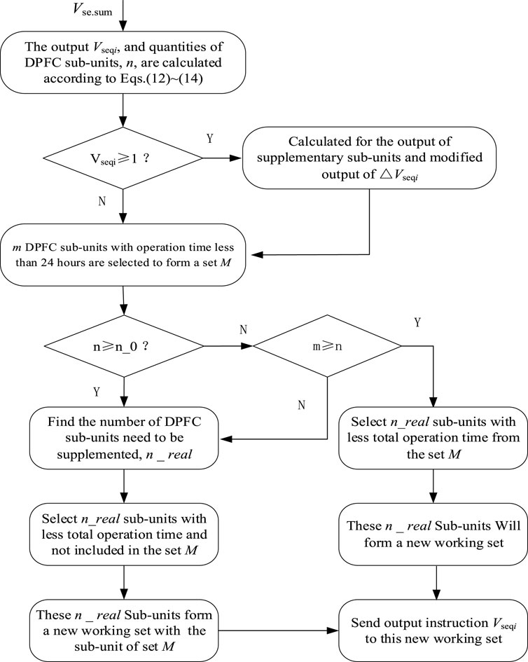
FIGURE 5. Flow chart of output distribution strategy.
Simulation analysis of the DPFC output control strategy
In order to verify the correctness and effectiveness of the proposed DPFC output control strategy, the verification environment of the output allocation strategy is constructed based on the m code of Matlab, i.e., to make the rated output voltage of each DPFC sub-unit
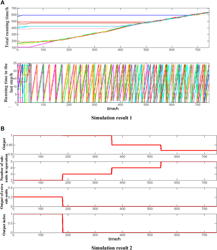
FIGURE 6. Simulation results of DPFC output distribution: (A) simulation result 1 and (B) simulation result 2.
As shown in Figure 6A, the total operation time of all DPFC sub-units is different from the initial value of operation time in the last step. However, as the simulation time passes, the total running time of each DPFC sub-unit is gradually consistent, and the working time of each DPFC sub-unit in the previous step is limited to within 24 h. This is because the sub-unit with a smaller total running time will operate for a longer time to ensure that each DPFC sub-unit is fully utilized and that the total running time of each DPFC unit is most balanced. As shown in Figure 6B, the output of DPFC sub-unit is generally maintained at full rated output between 1h–360 h, and the number of working sub-units changes from 2 to 3. However, in 1–180 h, due to the obtained DPFC unit output instructions
Conclusion
The disadvantages of the existing output control strategy are analyzed in this article. In addition, a coordination strategy of output voltage capability and the number of input sub-units is proposed. The simulation results are as follows:
1) The output distribution strategy proposed in this article can ensure that all DPFC sub-units in operation are maintained at a high output state (excluding supplementary units) all along the operation time, and the capacity of DPFC units in operation is fully utilized.
2) The shift mechanism of the proposed output distribution strategy can ensure that all DPFC sub-units are involved in the power flow control task, which is a good solution to the rapid decline of reliability caused by the long-term work of some DPFC units, so as to improve the overall reliability of DPFC device and its service life.
Data availability statement
The raw data supporting the conclusion of this article will be made available by the authors, without undue reservation.
Author contributions
AT and XC contributed to the conception and design of the study. WZ and BX organized the database. XC performed the statistical analysis. XC contributed to the validation of the study. AT and BX contributed to the resources of the study. XC wrote the first draft of the manuscript. WZ, AT, and BX wrote sections of the manuscript. All authors contributed to manuscript revision and read and approved the submitted version.
Funding
The Science and Technology Project of State Grid Zhejiang Electric Power Co. Ltd (B311DS22100A).
Conflict of interest
The authors declare that this study received funding from State Grid Zhejiang Electric Power Co., Ltd. The funder had the following involvement in the study: study design, data collection and analysis, decision to publish, preparation of the manuscript.
Publisher’s note
All claims expressed in this article are solely those of the authors and do not necessarily represent those of their affiliated organizations, or those of the publisher, the editors, and the reviewers. Any product that may be evaluated in this article, or claim that may be made by its manufacturer, is not guaranteed or endorsed by the publisher.
References
Brissette, A., Maksimovic, D., and Levron, Y. (2015). Distributed series static compensator deployment using a linearized transmission system model. IEEE Trans. Power Deliv. 30 (03), 1269–1277. doi:10.1109/tpwrd.2014.2362764
Chen, S., Lin, Q., Chen, S., Cai, F., and Wang, W. (2019). Review on intelligence fault diagnosis in power electronic converters[J]. Electr. Eng. 20 (03), 6–12.
Elgebaly, Ahmed E. (2019). “Optimized design of single tum transformer of distributed static series compensators using fem based on ga[C],” in 2019 21st International Middle East Power Systems Conference, 1133–1138.
Gaigowal, S. R., and Renge, M. M. (2016). “Distributed power flow controller using single phase DSSC to realize active power flow control through transmission line[C],” in 2016 International Conference on Computation of Power, Energy Information and Commuincation, 747–751.
Guan, Minyuan, Shen, Jianliang, Lou, Ping, Jin, Guoliang, and Wu, Guoqiang (2021). Equivalence analysis of voltage, impedance and power relationships of distributed power flow controller based on cascaded H-bridge converter[J]. Adv. Technol. Electr. Eng. Energy 40 (07), 40–47.
Huang, J., and Gao, Y. (2019). “Converter fault diagnosis method based on principal component analysis combined with improved similarity classifier[C],” in 2019 Chinese Automation Congress, 5051–5054.
Huang, W., Zhang, N., Yang, J., Wang, Y., and Kang, C. (2019a). Optimal configuration planning of multi-energy systems considering distributed renewable energy. IEEE Trans. Smart Grid 10 (02), 1452–1464. doi:10.1109/tsg.2017.2767860
Huang, X., Qi, L., and Pan, J. (2019b). A new protection scheme for MMC-based MVdc distribution systems with complete converter fault current handling capability. IEEE Trans. Ind. Appl. 55 (05), 4515–4523. doi:10.1109/tia.2019.2917360
Kang, C., and Yao, L. (2017). Key scientific issues and theoretical research framework for power systems with high proportion of renewable energy[J]. Automation Electr. Power Syst. 41 (09), 2–11.
Ke, M., Marco, L., Frede, L., and Tamas, K. (2019). Thermal loading and lifetime estimation for power device considering mission profiles in wind power converter. IEEE Trans. Power Electron. 30, 590–602. doi:10.1109/TPEL.2014.2312335
Liu, Bin, Liu, Jun, Xiong, Yong, and Lu, Xiongwei (2016). Technology of power proportionally distributed for paralleled inverters in microgrid[J]. Power Electron. 50 (01), 49–52.
Liu, B., Yang, Q., Zhang, H., and Wu, H. (2021). An interior-point solver for AC optimal power flow considering variable impedance-based FACTS devices. IEEE Access 9, 154460–154470. doi:10.1109/access.2021.3128035
Lou, W., Xiang, Z., Pan, W., Tang, A., Zhou, W., and Zhai, X. (2021). “Reserch on multi-mode operation of distributed power flow controller[C],” in 2021 IEEE 4th International Electrical and Energy Conference, 1–6.
Mao, Wenjin, Li, Hongwei, and Chao, Li (2017). A distribution system reconfiguration method considering the optimal active power dispatching of DGs[J]. Power Syst. Prot. Control 45 (13), 57–63.
Peddakapu, K., Mohamed, M. R., Sulaiman, M. H., Srinivasarao, P., Veerendra, A. S., and Leung, P. K. (2020). Performance analysis of distributed power flow controller with ultra-capacitor for regulating the frequency deviations in restructured power system[J]. J. Energy Storage 31 31. doi:10.1016/j.est.2020.101676
Qian, M., Zhao, D., Ma, J., Jiang, D., Ding, M., and Xiang, L. (2018). “A centralized frequency regulation strategy of PV power plant based equal adjustable capacity proportion mode[C],” in 2018 China International Conference on Electricity Distribution, 1797–1801.
Rashed, G. I., Haider, H., and Shafik, M. B. (2020). Enhancing energy utilization efficiency of Pakistani system considering FACTS devices and distributed generation: Feasibility study. Chin. J. Electr. Eng. 6 (2), 66–82. doi:10.23919/cjee.2020.000012
Saeed, P., Wang, Z., and Frede, B. (2019). “Reliability modeling of power electronic converters: A general approach[C],” in 2019 IEEE 20th Workshop on Control and Modeling for Power Electronics, 1–7.
Shen, C., Cao, J., Tang, M., Wu, M., Lin, C., and Bai, J. (2021). Research on real-time control optimization application function of DPFC[J]. Zhejiang Electr. Power 40 (09), 55–61. doi:10.19585/j.zjdl.202109008
Song, Jingen, Xu, Hua, Zhang, Dianqing, and Xu, Ting (2022). Design and application of control system for distributed power flow controller[J]. Power Electron. 56 (05), 93–96.
Tang, A., Zhou, W., Song, J., Qiu, P., Chen, Q., Zhai, X., et al. (2022). Optimal output power coordinated control strategy of distributed power flow controller[J]. Int. J. Electr. Power & Energy Syst. 140, 140. doi:10.1016/j.ijepes.2022.108075
Xiong, B., Tang, J., Li, Y., Xie, C., Wang, Z., Zhang, X., et al. (2022). Design of A Two-Stage control strategy of vanadium redox flow battery energy storage systems for grid application. IEEE Trans. Sustain. Energy. doi:10.1109/TSTE.2022.3181751
Zhan, X., Wang, Y., Zhao, G., and Zhu, N. (2019). Research and design of distributed static synchronous series compensator[J]. Power Electron. 53 (03), 95–98.
Zhang, C., Zhao, S., and He, Y. (2022). An integrated method of the future capacity and RUL prediction for lithium-ion battery pack. IEEE Trans. Veh. Technol. 71 (3), 2601–2613. doi:10.1109/tvt.2021.3138959
Zhao, S., Zhang, C., and Wang, Y. (2022). Lithium-ion battery capacity and remaining useful life prediction using board learning system and long short-term memory neural network. J. Energy Storage 52, 104901. doi:10.1016/j.est.2022.104901
Keywords: power systems, distributed power flow controller, fault probability, output voltage capability, number of switching sub-units
Citation: Chen X, Tang A, Xiong B and Zhou W (2022) Research on the output coordinated strategy of a DPFC considering device fault probability. Front. Energy Res. 10:985316. doi: 10.3389/fenrg.2022.985316
Received: 03 July 2022; Accepted: 13 July 2022;
Published: 31 August 2022.
Edited by:
Chaolong Zhang, Anqing Normal University, ChinaReviewed by:
Chuan-Ke Zhang, China University of Geosciences Wuhan, ChinaPengfei Tu, Nanyang Technological University, Singapore
Wang Xiang, Huazhong University of Science and Technology, China
Copyright © 2022 Chen, Tang, Xiong and Zhou. This is an open-access article distributed under the terms of the Creative Commons Attribution License (CC BY). The use, distribution or reproduction in other forums is permitted, provided the original author(s) and the copyright owner(s) are credited and that the original publication in this journal is cited, in accordance with accepted academic practice. No use, distribution or reproduction is permitted which does not comply with these terms.
*Correspondence: Aihong Tang, dGFoQHdodXQuZWR1LmNu