 Junyang Tian
 Liandian Jiang1
 Hongbo Wei
95% of researchers rate our articles as excellent or good
Learn more about the work of our research integrity team to safeguard the quality of each article we publish.
Find out more
ORIGINAL RESEARCH article
Front. Energy Res. , 02 September 2022
Sec. Smart Grids
Volume 10 - 2022 | https://doi.org/10.3389/fenrg.2022.981404
This article is part of the Research Topic Control, Operation and Trading Strategies of Intermittent Renewable Energy in Smart Grids View all 46 articles
It is important to select the fault line rapidly when single-phase grounding fault occurs in the small current grounding system. The fault information acquisition of existing methods generally need hardware modification, so the high cost makes it difficult to apply to the power grid in underdeveloped areas. Taking that into consideration, this paper proposed a method of steady-state information small current grounding fault line selection based on Optimization Spiking Neural P Systems (OSNPS). The method only needs the steady-state voltage and current data of the dispatch side to effectively identify the fault line, which greatly improves the range of application. According to the characteristics of power dispatching big data, the objective function is established and the normalized model parameters are optimized by OSNPS to improve the accuracy of fault line selection stably. Furthermore, PSCAD/EMTDC is used to simulate the small current grounding system, the main factors affecting the accuracy of fault line selection are analyzed and the relationship between fault information features and fault identification accuracy is revealed. What’s more, It is pointed out that the model parameters without optimization may have line selection failure. Finally, specific examples are given to verify that the model parameters optimized by OSNPS can effectively improve the accuracy of fault line selection.
Fault line selection of small current grounding system has been a hot issue in the power system. The accuracy of fault line selection is important to ensure the safe and reliable working of the power system (Guo and Wu, 2010; Guo et al., 2015; Jun et al., 2019). Depending on the source of fault information and the differences of deployment way, the existing methods of fault line selection can be generally divided into two categories: plant side and dispatch master side.
There are many ways to obtain fault information at the plant side, which can be roughly divided into three categories according to the types of fault signal: injected signal method, transient signal method and steady-state signal method. Injection signal method is to inject a specific disturbance signal into the system after a fault occurs and to select the fault line by comparing the distribution characteristics of the injected signal in each feeder (Zhu et al., 2011; Liu and Deng, 2019; Niu et al., 2021). Transient signal method is to record the signals of voltage and current at the moment of the fault occurring by a high-speed data acquisition device. Intelligent algorithms such as wavelet packet, Hilbert transform and differential filtering have been used to extract transient features components and select fault line by comparing transient feature signals (Xue et al., 2014; Lai et al., 2015; Zhang et al., 2016; Sun et al., 2017; Xu et al., 2018; Zhang et al., 2018). Although these two types of methods can effectively improve the accuracy of fault line selection, both require the installation of additional hardware in the distribution network, which is more economically expensive and difficult to implement, so they are not widely used. The third method mainly uses various steady-state characteristics of zero sequence currents (Guo-biao et al., 1995; Wang et al., 2014; Liu and Ma, 2015; Zhang et al., 2015). However, in economically underdeveloped regions, the construction method is widely used to install only two-phase current transformers at the feeder, without zero sequence current transformers. This method also faces the problems of high cost and difficulty in large-scale implementation.
Since the information at the dispatch side is affected by differences in data transmission, storage and processing capabilities, there are relatively few existing analyses of fault line selection methods based on data at the dispatch side. The literature (Zhu, 2019) proposed a fault line selection method for steady-state zero sequence current based on SCADA system. However, in the current practice, the actual zero sequence current sampling coverage rate is less than 50% in a large number of economically underdeveloped areas, so it is necessary to improve the zero sequence loop of each branch, resulting in high investment and operation and maintenance costs. In the literature (Xu et al., 2021), a dispatching side selection strategy based on the fusion of reactive power and current variation is proposed, but its fusion operator is simply half of each without effective optimization. At present, with the continuous development of smart grid, the demand of using SCADA system to realize the detection of small current single-phase grounding fault is increasing. The large amount of data in the system can achieve this purpose after processing. The processing of a large number of steady-state information requires the establishment of a relevant mathematical model, and the selection of the relevant parameters in the mathematical model is found to have a significant impact on the accuracy of the established mathematical model through data analysis (Chen and Wang, 2021), thus it is also crucial to find the most optimal parameters through optimization algorithms.
Membrane computing (MC) (Pan et al., 2019; Leporati et al., 2020; Zhang, 2021), a new branch of natural computing, has developed into an important research direction in the past decades. MC (the models are called P systems), initiated by Prof. Pǎun (P˘aun, 2000), abstracts computing models inspired from the structure and the functioning of the biological cells, organs and colonies of bacteria. In February 2003, MC was considered as an “emerging research front in computer science” by Institute for Scientific Information (ISI). Parallelism (multiple neurons of P systems work in parallel) is one of the most basic and typical features, and is often used to improve computational efficiency (Alhazov, 2010). At present, there are various types of membrane systems in terms of their membrane structures: cell-like P systems (Pan et al., 2020; Orellana-Mart´ın et al., 2019; Song et al., 2021), tissue-like P systems (Freund et al., 2005; Song et al., 2017; Valencia-Cabrera and Song, 2020; Ceterchi et al., 2021), neural-like P systems (Jiang et al., 2019; Ren et al., 2019; Lv et al., 2021; Zhang and Mario, 2021; Dong et al., 2022a; Zhang et al., 2022), and so on. These membrane computing models not only stay in the theoretical research, but also are used to solve various real-life application problems like medical image processing (Hu et al., 2020; Li et al., 2020; Xue et al., 2021), robot control (Wang et al., 2020; Wang et al., 2021), fault diagnosis (Wang et al., 2015; Rong et al., 2019; Zhang X. et al., 2021a), and other real-world problems (Zhang et al., 2017). Spiking neural P (SN P) systems (Ionescu et al., 2006; Pan et al., 2017; Zhang G. et al., 2021b; Wu and Jiang, 2021), extended neural P systems, transmits spikes to other connected neurons through synapses.
Optimization Spiking Neural P Systems (OSNPS), as a type of spiking neural membrane system, is capable of generating complete binary sequences (Zhang et al., 2014; Zhu et al., 2020; Rong et al., 2022), which means that this membrane system is theoretically capable of representing real number parameters within arbitrary constraints. Therefore, OSNPS is highly suitable for solving parametric optimization problems (Deng et al., 2022). In addition, the study of OSNPS not only refines the membrane system itself, but also provides ideas for exploring new methods of power system fault diagnosis.
In this paper, due to the data characteristics of neutral ungrounded system stored in the power dispatch system and the advantages of OSNPS, the simulation modeling of PSCAD/EMTDC is performed for the neutral ungrounded system of 10 kV distribution network, and the data of steady-state current and reactive power in the ungrounded system are collected. Secondly, the objective function is established and the function is optimized by OSNPS. The practice of this method proves that it can obviously improve the speed and accuracy of fault line selection.
The simplest equivalent network for a system with ungrounded neutral points of both power source and load is shown in Figure 1.
FIGURE 1. Distribution of capacitive current in single-phase to ground fault with neutral ungrounded.
In normal operation, the same capacitance
When the single-phase grounding fault occurs, the zero sequence current in the normal line is the capacitive current of line I itself, and the direction of capacitive reactive power flows from the busbar to the line. When there are multiple lines in the distribution network, the conclusion applies to each non-faulty line.
At the power source G, there are B-phase and C-phase to ground capacitive current, named
At the faulty line II, phases B and C flow through their own capacitive currents, named
The current effective value is:
Where,
The zero sequence current flowing at the beginning of line II is:
The effective value is:
The zero sequence equivalent network in case of single-phase grounding when the neutral point is not grounded is shown in Figure 2.
FIGURE 2. Zero sequence equivalent network for single-phase grounding.
There is a zero sequence voltage
In summary, when the neutral ungrounded system occurs single-phase grounding fault, the zero sequence current of fault line is numerically equal to the sum of capacitive current to ground of all the components in the non-faulty line. The capacitive reactive power is flowing from the line to the busbar, which happens to be different from the normal line, can be used as the line selection criteria.
As can be seen from the foregoing, in the neutral ungrounded system, the current flowing through the fault point in the fault line is the sum of the capacitive currents to ground of the components on the non-faulty line of the whole system. As a result, the reactive power at the fault line differs significantly from the reactive power amplitude of the non-faulty line. It can be used as part of the fusion criterion.
Based on the aforementioned analysis of the characteristic of faults in neutral ungrounded systems, and taking the complexity of the operation mode and the weakness of fault signal in the actual lines into account, the single-component criterion approach is not sufficient to ensure that effectively improve accuracy of fault selection. Therefore, the data components such as phase current and reactive power in the line are mainly used as the line selection criterion. The phase current is normalized by dispersion analysis, and then the phase current and reactive power are fused and multiple by the corresponding weights. This criterion is applied to the simulation data to obtain the accuracy of fault selection, and the optimal objective function is obtained by optimizing it with a pulsed membrane neural system.
The effective value of phase current and reactive power of the line can be calculated by collecting phase current and phase voltage of the line in the dispatching data, and at the same time calculate the change of phase current
From the aforementioned principle analysis, it can be obtained that in the ungrounded system, the change of phase current and reactive power when a single-phase ground fault occurs is more obvious, which can be used as the line selection criterion. Normalize the pre- and post-fault change data to facilitate the fusion criterion, and subsequently optimize the line selection weights in the two change quantities.
Normalization of the variation of phase currents:
Normalization of the amount of change in reactive power:
Where,
Calculation of the corresponding fault probability for all feeders at the busbar:
Where,
The single current or reactive power criterion can not meet the requirements of fault line selection in complex power grid and has certain limitations in the application of line selection in different grounding modes. Therefore, the parameter m (dimensionless) is used to fuse the two criterions. In addition, different values of m have a great impact on the accuracy of fault line selection, hence an optimization method is needed to optimize the value of m.
As a kind of optimization algorithm, the Optimization Spiking Neural P Systems (OSNPS) has the characteristics of parallelism (Zhang et al., 2020). Therefore, OSNPS enables to optimize parameters rapidly. The core idea of parameter optimization based on optimization spiking neural P systems is to first convert the parameters into binary pulse bursts as inputs to OSNPS, and then use the OSNPS to achieve parameter optimization (Dong et al., 2022b). In general, OSNPS includes two parts: the multiple Extended Spiking Neural P Systems (ESNPSs) and the Guider algorithm.
An ESNPS with degree m (m ≥ 1) is shown in Figure 3 and its formal definition is as follows (Dong et al., 2021):
In Eq. 8:
(1)
(2)
(3) syn represents the connection relationship (synapse) between neurons;
(4)
FIGURE 3. Extended spiking neural P system.
OPNPS consists of multiple ESNPSs, the number of which is H and each of which is defined and structured in Figure 3. An ESNPS family containing a Guider is called OSNPS. First, H ESNPSs are arranged in parallel and the Guider is added to support spikes to
FIGURE 4. Optimization spiking neural P system.
The parameter optimization in Eq. 7 is realized by using the guide algorithm designed in literature (Zhang et al., 2014), and the pseudo-code of the guide algorithm is shown in Supplementary Table S1.
According to the specific optimization objective function, the general processing flow is as follows:
(1) Convert the decimal of the optimized parameters to binary after preprocessing, followed by arranging the binary into a binary string (the current parameter
(2) The probability corresponding to the first individual in the population is adjusted according to the probability adjustment strategy until all probabilities corresponding to all individuals are adjusted.
(3) Repeat step (2) over and over again, and after the probabilities corresponding to all individuals in the population have been adjusted, proceed to the next iteration.
(4) After finding the optimal value, the iteration of the algorithm stops and the optimal value is output.
For the objective function derived in the second part, the objective function in Eq. 7 is solved using OSNPS. All the experiments are implemented on the platform PYTHON and on a work station with GPU 3080, 32 GB RAM and Windows 10. The specific solution procedure is as follows.
(1) Build the PSCAD parametric simulation model and obtain the data required for the model, such as label data, steady-state current data and steady-state reactive power data.
(2) Set the basic parameters of the model: In OSNPS, the basic parameters include the number of evolutionary populations
(3) Initialize model parameters: Enter relevant steady-state information, including steady-state current information before and after the fault, steady-state reactive power information before and after the fault, and label values corresponding to the fault line and the non-fault line.
(4) Calculate the fitness value: determine the number of optimization parameters, and establish a model of the optimized pulsed neural membrane system. The optimization parameters are used as the input of the optimized pulsed neural membrane system, and the optimized parameters are used as the inputs, and the output results of the optimized pulsed neural membrane system are performed.
(5) Verify the validity and correctness of the optimization parameters based on the results obtained by optimization spiking neural P systems.
The specific process is shown in Figure 5 below.
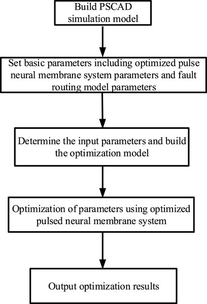
FIGURE 5. Schematic diagram of parameter determination and fault line selection.
This paper uses PSCAD/EMTDC to build a 10 kV small current grounding system disribution network simulation model as shown in Figure 6. All the experiments are implemented on the platform PSCAD/EMTDC45 and on a work station with GPU GTX960M, 8 GB RAM and Windows10.
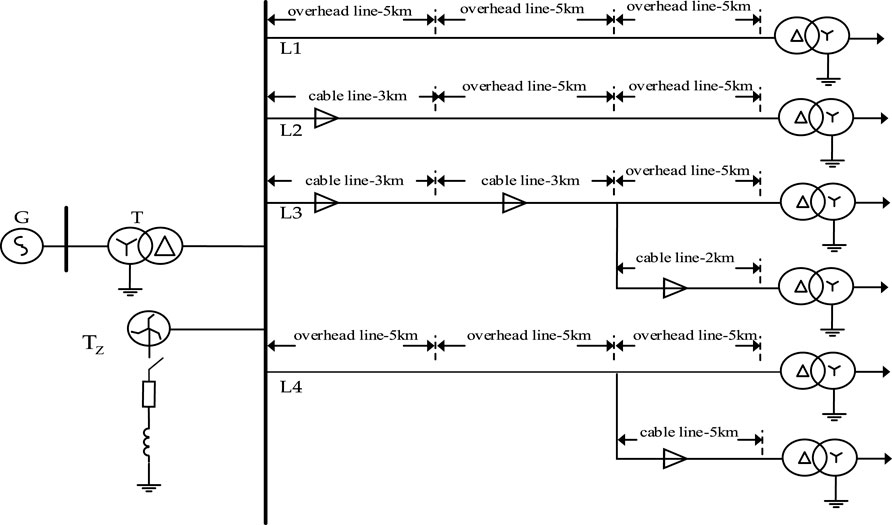
FIGURE 6. Neutral ungrounded system.
The model contains 4 lines (L1 ∼ L4), and the line types are overhead lines, cable lines, overhead cable hybrid lines. The simulation parameters related to the model are shown in Supplementary Table S2.
In this paper, a large number of simulations and analyses are made by PSCAD/EMTDC for the neutral point ungrounded system of the distribution network. In order to obtain data on faults occurring during stable operation of the system, the fault time is set at 2s and the duration is 0.4s. The conditions when a single-phase ground fault occurs are: (1) the fault line is line L1∼L4; (2) the fault is set at the end of the line in the simulation model for setting the different fault line lengths; (3) the grounding fault is set to 0Ω, 20Ω, 100Ω, 600Ω, 800Ω, 1000Ω. Because only the steady-state RMS data in the scheduling system is considered, the simulation is not considered for different fault closing angles, and a total of 120.
In 120 sets of data, each set of data mainly includes label data, steady-state current data and steady-state reactive power data. Some of the sample data are shown in Supplementary Table S3.
In order to further clarify the relationship between fault information features and fault identification accuracy and study its internal mechanism, this section analyzes the main influencing factors of fault line selection accuracy.
The fault line selection model established in the previous section is based on the IQ normalized criterion composed of the change of phase current and reactive power. Where, the current criterion is closely related to the capacitive current and the phase of the capacitive current is always 90° ahead of the voltage. Therefore, only the amplitude of the capacitive current is considered to be influenced by the capacitive reactance to ground. The reactive power criterion is related to the capacitive current and the amplitude and phase of line voltage, obviously which influenced by the transition resistance.
In summary, the main influencing factors of the proposed steady-state component selection method are the capacitive current to ground
Based on the simulation model established in Section 4.1, it is assumed that the fault occurs on line Lf and the other three non-fault lines are L1∼L3.
Supplementary Tables S4–S7 show the fault probabilities for Lf, L1, L2 and L3 (m = 0.5) obtained from the variations of transition resistance and capacitive current when the fault location and load current are fixed.
As can be seen from Supplementary Table S4 to Supplementary Table S7, when the capacitive current
In addition, when the
From the above analysis, it is clear that when the capacitive current is small and at the same time the transition resistance is large, the original selection method without optimization of the fusion operator may result in a wrong selection.
To further illustrate the law of grounding probability with the variation of capacitive current
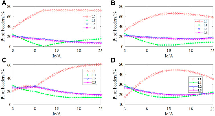
FIGURE 7. The characteristics of the grounding probability with the variation of capacitive current
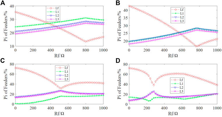
FIGURE 8. The characteristics of the grounding probability with the variation of transition resistance
The law of the grounding probability of each line with the variation of the system capacitive current
(a) and (b) of Figure 7 show the characteristics of the grounding probability with the variation of capacitive current
(c) and (d) of Figure 7 show the characteristics of the grounding probability with the variation of capacitive current
The law of the grounding probability of each line with the variation of transition resistance
(a) and (b) of Figure 8 show the characteristics of the grounding probability with the variation of capacitive current
The optimal parameter values of m and n are solved according to the known sample data and Eq. 7 in Section 3.1. The trend of m during its 20 independent optimization and the final results are shown in Figure 9.
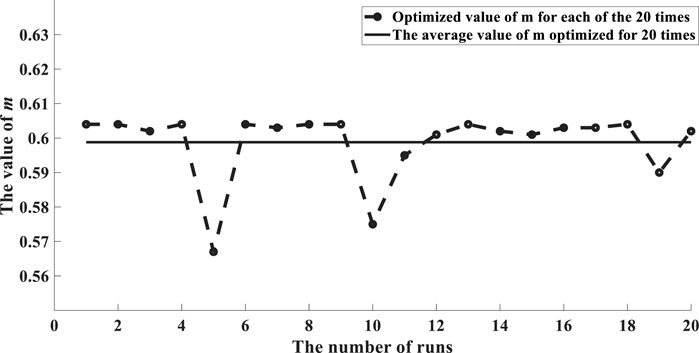
FIGURE 9. Parameter optimization results.
Based on the results after 20 independent optimizations, the average value of m is taken as the final value in order to reduce the error. The resulting objective function is shown in Eq. 9.
The 40 sets of test data were validated according to Eq. 9 and their accuracy was obtained as 99.79%. Therefore, the line selection model established in this paper and the applied parameter optimization method are feasible and effective for the selection of the line of the steady-state information single-phase grounding fault.
In this paper, due to the data characteristics of neutral ungrounded system stored in the power dispatch system and the advantages of OSNPS, the simulation modeling of PSCAD/EMTDC is performed for the neutral ungrounded system of 10 kV distribution network, the parameters are optimized by OSNPS and the line selection model is finally determined.The following conclusions are obtained through experiments and research analysis.
(1) The established fault line selection model can effectively identify fault lines by steady-state current and power alone, improving the practical application of the model.
(2) The parameters determined by OSPNS can effectively identify the fault line and the recognition accuracy can reach 99.79%.
(3) It provides a better choice for the traditional manual method of fault line selection and can effectively improve the efficiency of selection.
The original contributions presented in the study are included in the article/Supplementary Material, further inquiries can be directed to the corresponding author.
JT: Conception and design of the study, Algorithm, Writing—original draft. LJ: Statistical analysis, Writing—second draft. HL: Validation, Writing—review and editing. HW: Data curation. YL: Investigation. All authors contributed to manuscript revision and read and approved the submitted version.
This work was supported by Science and Technology Project of Guangxi Power Grid Corporation “Research and application of key technologies of fuzzy diagnosis of power grid faults based on artificial intelligence image recognition” under grant GXDWKJXM20190680.
Authors JT, LJ, HL and HW are employed by the company Guangxi Power Grid Dispatching Control Center, China Southern Power Grid Company Limited.
The remaining authors declare that the research was conducted in the absence of any commercial or financial relationships that could be construed as a potential conflict of interest.
All claims expressed in this article are solely those of the authors and do not necessarily represent those of their affiliated organizations, or those of the publisher, the editors and the reviewers. Any product that may be evaluated in this article, or claim that may be made by its manufacturer, is not guaranteed or endorsed by the publisher.
The Supplementary Material for this article can be found online at: https://www.frontiersin.org/articles/10.3389/fenrg.2022.981404/full#supplementary-material
Alhazov, A. (2010). Minimal parallelism and number of membrane polarizations. triangle 18 (18), 1–170. doi:10.17345/triangle6.1-17
Ceterchi, R., Orellana-Mart´ın, D., and Zhang, G. (2021). Division rules for tissue P systems inspired by space filling curves. J. Membr. Comput. 3 (2), 105–115. doi:10.1007/s41965-021-00071-5
Chen, B., and Wang, Y. (2021). Short-term electric load forecasting of integrated Energy system considering nonlinear synergy between different loads. IEEE Access 9, 43562–43573. doi:10.1109/ACCESS.2021.3066915
Deng, X., Dong, J., Wang, S., Luo, B., Feng, H., and Zhang, G. (2022). Reducer lubrication optimization with an optimization spiking neural P system. Inf. Sci. 604, 28–44. doi:10.1016/j.ins.2022.05.016
Dong, J., Luo, B., and Zhang, G. (2022b). Automatic design of arithmetic operation spiking neural P systems. Nat. Comput 2022, 1–13. doi:10.1007/s11047-022-09902-5
Dong, J., Zhang, G., Luo, B., Yang, Q., Guo, D., Rong, H., et al. (2022b). A distributed adaptive optimization spiking neural P system for approximately solving combinatorial optimization problems. Inf. Sci. 596, 1–14. doi:10.1016/j.ins.2022.03.007
Dong, J., Stachowicz, M., Zhang, G., Cavaliere, M, Rong, H, and Paul, P. (2021). Automatic design of spiking neural P systems based on genetic algorithms. Int. J. Unconv. Comput. 16 (2-3), 201–216.
Freund, R., P˘aun, G., and P´erez-Jim´enez, M. J. (2005). Tissue P systems with channel states. Theor. Comput. Sci. 330 (1), 101–116. doi:10.1016/j.tcs.2004.09.013
Guo, L., Xue, Y., Xu, B., and Zhang, S. (2015). Research on effects of neutral grounding modes on power supply reliability in distribution networks[J]. Power Syst. Technol. 39 (8), 2340–2345. doi:10.13335/j.1000-3673.pst.2015.08.041
Guo, Q., and Wu, T. (2010). Summary of fault line selection methods for small current grounding system[J]. Power Syst. Prot. Control 38 (2), 146–152. doi:10.3969/j.issn.1674-3415.2010.02.036
Guo-biao, T., Tu, D., and Da-peng, C. (1995). Microcomputerized faulty line discriminator based on theory of maximizing isinψ or △(Isinψ) [J]. Electr. Power 7, 16–20+72. CNKI:SUN:ZGDL.0.1995-07-003.
Hu, J., Wang, Y., Kong, D., Yan, F., and Xue, J. (2020). Hypergraph membrane system based F2 fully convolutional neural network for brain tumor segmentation. Appl. Soft Comput. 94, 106454. doi:10.1016/j.asoc.2020.106454
Ionescu, M., P˘aun, G., and Yokomori, T. (2006). Spiking neural P systems. Fundam. Inf. 71 (2), 279–308. doi:10.1109/BICTA.2010.5645192
Jiang, Y., Su, Y., and Luo, F. (2019). An improved universal spiking neural P system with generalized use of rules. J. Membr. Comput. 1 (8), 270–278. doi:10.1007/s41965-019-00025-y
Jun, Z., Jiewen, D., Chenwang, H., Zhanpeng, R., Yongqi, X., and Jinglu, L. (2019). Analysis and application of neutral displacement voltage trajectory of single phase grounding fault in asymmetric power grid[J]. Automation Electr. Power Syst. 43 (5), 159–173. doi:10.7500/AEPS20180811004
Lai, P., Zhou, X., and Qiu, D. (2015). Research on transient-current frequency analysis and faulty line detecting method in indirectly grounding power system[J]. Power Syst. Prot. Control 43 (4), 51–57. doi:10.7667/j.issn.1674-3415.2015.04.008
Leporati, A., Manzoni, L., Claudio, Z., Porreca, A., and Zandron, C. (2020). A turing machine simulation by p systems without charges. J. Membr. Comput. 2 (2), 71–79. doi:10.1007/s41965-020-00031-5
Li, B., Peng, H., Luo, X., Wang, J., Riscos-N´u˜nez, A., Perez-Jimenez, M. J., et al. (2020). Medical image fusion method based on coupled neural P systems in nonsubsampled shearlet transform domain. Int. J. Neural Syst. 31 (1), 2050050–2050117. doi:10.1142/s0129065720500501
Liu, B., and Ma, H. (2015). Transition resistance measurement and fault phase selection under single-phase ground fault based on producing mechanism of zero-sequence voltage[J]. Power Syst. Technol. 39 (5), 1444–1449. doi:10.13335/j.1000-3673.pst.2015.05.041
Liu, Z. Y., and Deng, C. H. (2019). Single-phase ground fault line selection method in active distribution networks based on high-voltage inverter injected signals [J]. Dyna (Medellin). 94 (5), 539–545. doi:10.6036/9221
Lv, Z., Yang, Q., Peng, H., Song, X., and Wang, J. (2021). Computational power of sequential spiking neural P systems with multiple channels. J. Membr. Comput. 3 (2), 270–283. doi:10.1007/s41965-021-00089-9
Niu, L., Wu, G. Q., and Xu, Z. S. (2021). Single-phase fault line selection in distribution network based on signal injection method. Ieee Access 9, 21567–21578. doi:10.1109/ACCESS.2021.3055236
Orellana-Mart´ın, D., Valencia-Cabrera, L., Riscos-N´u˜nez, A., and P´erezJim´enez, M. J. (2019). Minimal cooperation as a way to achieve the efficiency in cell-like membrane systems. J. Membr. Comput. 1 (1), 85–92. doi:10.1007/s41965-018-00004-9
Pan, L., Paun, G., Zhang, G., and Neri, F. (2017). Spiking neural P systems with communication on request. Int. J. Neural Syst. 27 (8), 1750042–1175004213. doi:10.1142/s0129065717500423
Pan, L. Q., Orellana-Mart´ın, D., Song, B., and P´erez-Jim´enez, M. J. (2020). Cell-like P systems with polarizations and minimal rules. Theor. Comput. Sci. 816, 1–18. doi:10.1016/j.tcs.2019.10.001
Pan, L. Q., P˘aun, G., and Zhang, G. X. (2019). Foreword: Starting JMC. J. Membr. Comput. 1 (1), 1–2. doi:10.1007/s41965-019-00010-5
P˘aun, G. (2000). Computing with membranes. J. Comput. Syst. Sci. 61 (1), 108–143. doi:10.1006/jcss.1999.1693
Ren, T., Cabarle, F. G., and Adorna, H. N. (2019). Generating context-free languages using spiking neural P systems with structural plasticity. J. Membr. Comput. 1 (8), 161–177. doi:10.1007/s41965-019-00021-2
Rong, H., Duan, Y., and Zhang, G. (2022). A bibliometric analysis of membrane computing (1998-2019). J. Membr. Comput. 2022, 1–31.doi:10.1007/s41965-022-00098-2
Rong, H., Yi, K., Zhang, G., Dong, J., Paul, P., and Huang, Z. (2019). Automatic implementation of fuzzy reasoning spiking neural P systems for diagnosing faults in complex power systems. Complexity 2019, 1–16. doi:10.1155/2019/2635714
Song, B., Luo, X., Peng, H., Valencia-Cabrera, L., and Zeng, X. (2021). The computational power of cell-like P systems with one protein on membrane. J. Membr. Comput. 2 (4), 332–340. doi:10.1007/s41965-020-00063-x
Song, B. S., Zhang, C., and Pan, L. Q. (2017). Tissue-like P systems with evolutional symport/antiport rules. Inf. Sci. (N. Y). 378, 177–193. doi:10.1016/j.ins.2016.10.046
Sun, G., Wang, J., Zhang, X., Liu, G., Sun, T., and Li, L. (2017). Small current grounding fault location method of distributed intelligence[J]. Power Syst. Prot. Control 45 (16), 72–78. doi:10.7667/PSPC161172
Valencia-Cabrera, L., and Song, B. (2020). Tissue P systems with promoter simulation with mecosim and p-lingua framework. J. Membr. Comput. 2 (2), 95–107. doi:10.1007/s41965-020-00037-z
Wang, T., Zhang, G. X., Zhao, J. B., He, Z. Y., Wang, J., P´erez-Jim´enez, M. J., et al. (2015). Fault diagnosis of electric power systems based on fuzzy reasoning spiking neural P systems. IEEE Trans. Power Syst. 30 (3), 1182–1194. doi:10.1109/tpwrs.2014.2347699
Wang, X., Xiang-xiang, W., Gao, J., and Hou, Y. (2014). A novel fault line selection method based on EEMD-hilbert and SVM for distribution network [J]. Proc. CSU-EPSA 26 (12), 55–61. doi:10.3969/j.issn.1003-8930.2014.12.009
Wang, X., Zhang, G. X., Gou, X. T., Paul, P., and Zhang, H. (2020). A membrane parallel rapidly-exploring random tree algorithm for robotic motion planning. Integr. Comput. Aided. Eng. 27 (2), 121–138. doi:10.3233/ica-190616
Wang, X., Zhang, G. X., Gou, X. T., Paul, P., Zhang, H., Rong, H., et al. (2021). Multi-behaviors coordination controller design with enzymatic numerical P systems for robots. Integr. Comput. Aided. Eng. 28 (2), 119–140. doi:10.3233/ica-200627
Wu, T., and Jiang, S. (2021). Spiking neural P systems with a flat maximally parallel use of rules. J. Membr. Comput. 3 (3), 221–231. doi:10.1007/s41965-020-00069-5
Xu, M., Gao, S., Chang, Z., Ma, J., Chen, W., and Song, G. (2018). Model recognition based single-phase earthed faulty line selection method of Petersen coil grounded system[J]. Power Syst. Prot. Control 46 (2), 73–78. doi:10.7667/PSPC162117
Xu, P., Tang, J., Yang, X., Hu, Y., and Zhou, Y. (2021). Selection scheme of small current grounding line at dispatching terminal based on multi-component fusion [J]. Sichuan Electr. Power Technol. 44 (3), 76–81. doi:10.16527/j.issn.1003-6954.20210314
Xue, J., Wang, Y., Kong, D., Wu, F., Liu, X., Qu, J., et al. (2021). Deep hybrid neural-like P systems for multiorgan segmentation in head and neck CT/MR images. Expert Syst. Appl. 168 (27), 114446. doi:10.1016/j.eswa.2020.114446
Xue, Y., Zhang, Q., Yan, T., and Xu, B. (2014). Faulty feeder identification based on combined transient and powerfrequency components in resonant grounded system[J]. Automation Electr. Power Syst. 38 (24), 80–85. doi:10.7500/AEPS20131210015
Zhang, B., Zhiguo, H., and Zhiqian, B. (2016). New development in relay protection for smart grid[J]. Prot. Control Mod. Power Syst. 1 (1), 121–127.
Zhang, G., and Mario, J. (2021). “Pérez-jiménez, agustín riscos-nuñez, sergey verlan, savas konur, thomas hinze, marian gheorghe,” in Membrane computing models: Implementations (Singapore: Springer).
Zhang, G., Rong, H., Paul, P., He, Y., Neri*, F., and Pérez-Jiménez, M. J. (2021). A complete arithmetic calculator constructed from spiking neural P systems and its application to information fusion. Int. J. Neural Syst. 31 (1), 2050055. Article No. 2050055. doi:10.1142/s0129065720500550
Zhang, G., Shang, Z., Verlan, S., Miguel, A., Yuan, C., Valencia-Cabrera, L., et al. (2020). An overview of hardware implementation of membrane computing models. ACM Comput. Surv. 53 (4), 1–38. Article No. 90. doi:10.1145/3402456
Zhang, G., Shu, H., Yu, J., and Sun, X. (2015). Double-ended travelling wave fault location independent of two side TimeSynchronization[J]. Trans. China Electrotech. Soc. 30 (20), 199–209. doi:10.3969/j.issn1000-6753.2015.20.025
Zhang, G., Zhang, X., Rong, H., Paul, P., Zhu, M., Neri*, F., and Ong, Y.-S. (2022). A layered spiking neural system for classification problems. Int. J. Neural Syst. 32, 2250023. doi:10.1142/S012906572250023X
Zhang, G., Pérez-Jiménez, M., and Gheorghe, M. (2017). Real-life applications with membrane computing. Emergence, complexity and computation. Cham: Springer. doi:10.1007/978-3-319-55989-6
Zhang, G. X. (2021). Membrane computing. Int. J. Parallel, Emergent Distributed Syst. 36 (1), 1–2. doi:10.1080/17445760.2019.1659260
Zhang, G. X., Rong, H. N., Neri, F., and Perez-Jimenez, M. J. (2014). An optimization spiking neural p system for approximately solving combinatorial optimization problems[J]. Int. J. Neural Syst. 24 (5), 1440006–1440016. doi:10.1142/S0129065714400061
Zhang, N., Zhang, J., Zheng, C., and Ding, L. (2018). Fault section location based on similarity of zero sequence current amplitude distribution in non-solidly-earthed network[J]. Power Syst. Prot. Control 46 (13), 120–125. doi:10.7667/PSPC170963
Zhang, X., Zhang, G., Paul, P., Zhang, J., Wu, T., Fan, S., and Xiong, X. (2021). Dissolved gas analysis for transformer fault based on learning spiking neural P system with belief AdaBoost. Int. J. Unconv. Comput. 16 (2-3), 239–258.
Zhu, K., Zhang, P., Wang, W. C., and Xu, W. (2011). Controlled closing of PT delta winding for identifying faulted lines. IEEE Trans. Power Deliv. 26 (1), 79–86. doi:10.1109/TPWRD.2010.2064340
Zhu, M., Yang, Q., Dong, J., Zhang, G., Neri, F., Rong, H., et al. (2020). An adaptive optimization spiking neural P system for binary problems. Int. J. Neural Syst. 31 (1), 2050054. doi:10.1142/S0129065720500549
Keywords: fault line selection, small current grounding system, fault characteristics, objective function, optimization spiking neural P systems
Citation: Tian J, Jiang L, Li H, Wei H and Liu Y (2022) A method of single-phase grounding fault line selection based on optimization spiking neural P systems. Front. Energy Res. 10:981404. doi: 10.3389/fenrg.2022.981404
Received: 29 June 2022; Accepted: 21 July 2022;
Published: 02 September 2022.
Edited by:
Biyun Chen, Guangxi University, ChinaReviewed by:
Gexiang Zhang, Chengdu University of Information Technology, Chengdu, ChinaCopyright © 2022 Tian, Jiang, Li, Wei and Liu. This is an open-access article distributed under the terms of the Creative Commons Attribution License (CC BY). The use, distribution or reproduction in other forums is permitted, provided the original author(s) and the copyright owner(s) are credited and that the original publication in this journal is cited, in accordance with accepted academic practice. No use, distribution or reproduction is permitted which does not comply with these terms.
*Correspondence: Junyang Tian, R3V6eHgyMDIyQDE2My5jb20=
Disclaimer: All claims expressed in this article are solely those of the authors and do not necessarily represent those of their affiliated organizations, or those of the publisher, the editors and the reviewers. Any product that may be evaluated in this article or claim that may be made by its manufacturer is not guaranteed or endorsed by the publisher.
Research integrity at Frontiers
Learn more about the work of our research integrity team to safeguard the quality of each article we publish.