 Yuefeng Guo
 Binhang Zhang
 Xianbao Yuan1,2*
94% of researchers rate our articles as excellent or good
Learn more about the work of our research integrity team to safeguard the quality of each article we publish.
Find out more
ORIGINAL RESEARCH article
Front. Energy Res., 26 September 2022
Sec. Nuclear Energy
Volume 10 - 2022 | https://doi.org/10.3389/fenrg.2022.973390
This article is part of the Research TopicExperimental and Numerical Studies on Liquid Metal Cooled Fast ReactorsView all 17 articles
The annular fuel has dual-cooled surfaces internally and externally. Compared with traditional cylindrical fuel, the inner flow field is introduced on the annular fuel assembly, and wire-wrapped can influence the inner flow field. In order to research and compare the effect of wire-wrapped on the sub-channels and inner flow field of the fast reactor annular fuel assembly, thermal-hydraulic properties of the fast reactor annular fuel assembly with the inner and outer wire-wrapped are investigated in this research. The flow, heat transfer, and mechanical properties are analyzed, including temperature, transverse velocity, pressure drop, and thermal stress. The temperature of three sub-channels is the key that influences the temperature characteristics. The wire-wrapped reduces the coolant temperature gradient, flattens the coolant outlet temperature, and makes the coolant outlet temperature more uniform. The transverse velocity of coolant in the sub-channels is about three times that of in the inner flow field. From the perspective of the inner flow field, the increase in the number of wire-wrapped leads to an increase in transverse velocity. The number of wire-wrapped is not as good as possible from the perspective of sub-channels. The pressure drop of the sub-channels is larger than the pressure drop of the inner flow field. No matter the sub-channels or the inner flow field, the increase in the number of wire-wrapped will cause an increase in the pressure drop. The thermal-hydraulic properties of one inner and outer wire-wrapped are better than other models. The stress in the cladding is about 1.75 times the stress in the annular fuel rod, and the stress in the inner cladding is higher than that in the outer cladding. The research provides a reference for the optimization design of the fuel assembly.
Sodium-cooled fast reactors are one of the reactors selected by international forums for generation IV nuclear energy systems that can use nuclear energy efficiently. In sodium-cooled fast reactors fuel assemblies, helical wire-wrapped is widely used to promote coolant mixing and prevent mechanical vibration between the fuel assembly. Many experiments are mainly focused on the thermo-hydraulic properties of wire-wrapped. Some important correlations are also developed in the experiments. Novendstern (1972) developed a semi-empirical model that can predict the pressure loss for a turbulent region with wire-wrapped. Rehme (1973) introduced an effective velocity to take into account the helical flow velocity around the rods caused by the wire-wrapped. Engel et al. (2017)introduced the intermittency factor to correlate with a friction factor based on their experimental results. Cheng and Todreas (1986)developed their friction factor correlations with a complicated model and upgraded their correlations twice till now (Chen S. K. et al., 2018; Pacio et al., 2022). Choi et al. (2003)developed a series of water experiments using a helical wire-wrapped 19-pin fuel assembly and performed a comparative study of five existing correlations. Bertocchi et al. (2019) and Wang et al. (2020) conducted some experiments to study the cross-flow caused by the wire-wrapped using particle image velocimetry. Chun and Seo (2001), Pacio et al. (2016), Hou et al. (2019), and Liang et al. (2020)studied the flow and heat transfer characteristics with wire-wrapped along with different fuel bundles. The abovementioned experiments on wire-wrapped are based on cylindrical fuel bundles.
With the dramatic increase in computer performance, it is more efficient to use numerical simulation to study the characteristics of sodium-cooled fast reactors wire-wrapped. The CFD method has great potential in the study of detailed three-dimensional flow and heat transfer characteristics in wire-wrapped compared with the experimental method. Gajapathy et al. (2015) and Raj and Velusamy (2016) studied the characterization of velocity and temperature fields in a 217-pin wire-wrapped fuel bundle of a sodium-cooled fast reactor. Chen J. et al. (2018) and Bieder et al. (2021) invested the pressure loss and velocity distribution in a 217-pin wire-wrapped fuel bundle. Wang and Cheng (2018) and Song et al. (2019) analyzed the sweeping flow and vortex behavior in the 19-pin and 37-pin wire-wrapped fuel assembly for a sodium fast reactor. Thermal-hydraulic comparisons of 19-pin rod bundles with four circular- and trapezoid-shaped wire-wrapped were performed in Liu et al. (2017)’s research. All of the abovementioned researchers have conducted rich analyses of the wire-wrapped structure, which has great significance. The abovementioned research studies on wire-wrapped are all carried out on the basis of cylindrical fuel bundles, and the wire-wrapped is located in the sub-channels, which causes the change of the thermal-hydraulic properties in the sub-channels. Like pressurized water reactors, annular fuel assemblies are employed in the sodium-cooled fast reactors. It is possible to improve the overall performance of sodium-cooled fast reactors.
The annular fuel has been proposed as one of the options to achieve higher power density, larger safety margin, and reduced electricity generation cost (Feng et al., 2007; Lahoda et al., 2007). The annular fuel, mainly utilized in pressurized water reactors, is less adopted in generation IV reactors. The United States (Kazimi et al., 2006; El-Sahlamy et al., 2020), South Korea (Shin et al., 2012), Iran (Zaidabadi et al., 2017), and other countries have used annular fuel assembly for active pressurized water reactors, proving many advantages of the annular fuel assembly. Rowinski et al. (2015)described the innovative model of annular fuel design for lead-cooled fast reactors. Due to the introduction of the inner flow field, the research on the mechanical properties of annular fuel assembly is of great significance. Zhao et al. (2004), Kwon et al. (2013),and Xu et al. (2020) analyzed the mechanical properties, such as thermal stress and displacement of PWR with annular fuel assembly. The abovementioned studies on the annular fuel assembly are focused on the PWR without the effect of the wire-wrapped. There are few studies on the mechanical properties of Sodium-cooled fast reactor annular fuel assembly.
In this research study, the effects of the annular fuel assembly and wire-wrapped on the flow, heat transfer, and mechanical properties are considered together of the sodium-cooled fast reactor. Due to the introduction of the inner flow field, the thermal-hydraulic properties of the 7-pin annular fuel assembly with the inner and outer wire-wrapped are investigated in this research. It is a whole new way of wire-wrapped. The flow, heat transfer, and mechanical properties are analyzed, including temperature, transverse velocity, pressure drop, and thermal stress. This article is organized as follows. Introduction introduces the geometry, mesh, and boundary conditions. Model validation is introduced in Introduction. Analysis results and discussions include temperature field, flow field, pressure drop, and thermal stress performances, which are described in Introduction. Finally, the conclusion and future works are given in Introduction.
The computational models of the annular fuel assembly with the inner and outer wire-wrapped for the Chinese Experimental Fast Reactor are developed in Computational models, which includes five parts, which are geometry models, mesh models, turbulence models, thermodynamic models, and boundary conditions.
The geometry models of the annular fuel assembly for the Chinese Experimental Fast Reactor (Cui et al., 2013) are established by 3D software based on the annular fuel assembly design principles, and the geometric parameters are shown in Table 1. The models are created according to the difference between the number and position of the wire-wrapped. The solid domain and fluid domain of the geometry models are shown in Figures 1 and 2. In all models, the winding direction of the wire-wrapped is clockwise, and the winding angle at the outlet of the wire-wrapped is 30°. When the number of wire-wrapped is two, the winding angle at the outlet of the wire-wrapped is different by 180°.
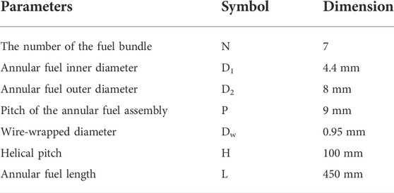
TABLE 1. Geometric parameters.
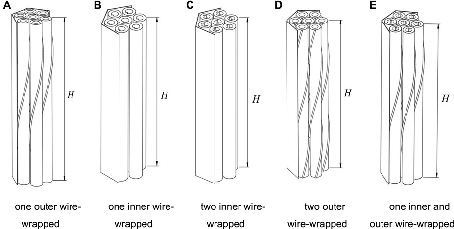
FIGURE 1. Geometry models (solid domain).
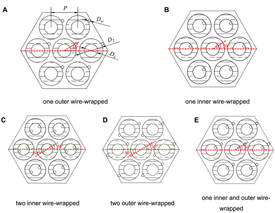
FIGURE 2. Geometry models (fluid domain).
The geometry models have been pre-processed by the design modeler. The geometry sharp angle is easily produced in the position where the connection between the wire-wrapped and the annular fuel rods, owing to the contraction in this location, is the line. In addition, it can cause an increase in the number of grids dramatically and a decrease in the quality easily. Both are moved toward each other by 0.05 mm in order to solve this problem. The effect of this treatment on the calculation can be ignored (Natesan et al., 2010). Fluent mesh is used to develop polyhedral mesh, and local meshes are refined around the wire-wrapped. The boundary layer is created at the contact surface between the fluid domain and the solid domain, and a high-quality mesh is obtained. Figure 3A shows the mesh for the thermal stress model at the outlet. Boundary layers are set where the solids and fluids are in contact. Table 2 depicts the number of grids of four cases in the five models. Figure 3B depicts the coolant average temperature in the interior sub-channel in different cases of the five models. The coolant average temperature in the interior sub-channel increases gradually with the increase of Z/Zm. The maximum errors of the five models are 0.007%, 0.38%, 0.05%, 0.6%, and 0.41%, respectively. These errors are within acceptable limits. Finally, the cases with consistent grid sizes are selected. The number of grids for the five models is 2.31million, 1.04million, 1.28million, 3.73million, and 3.20million, respectively.
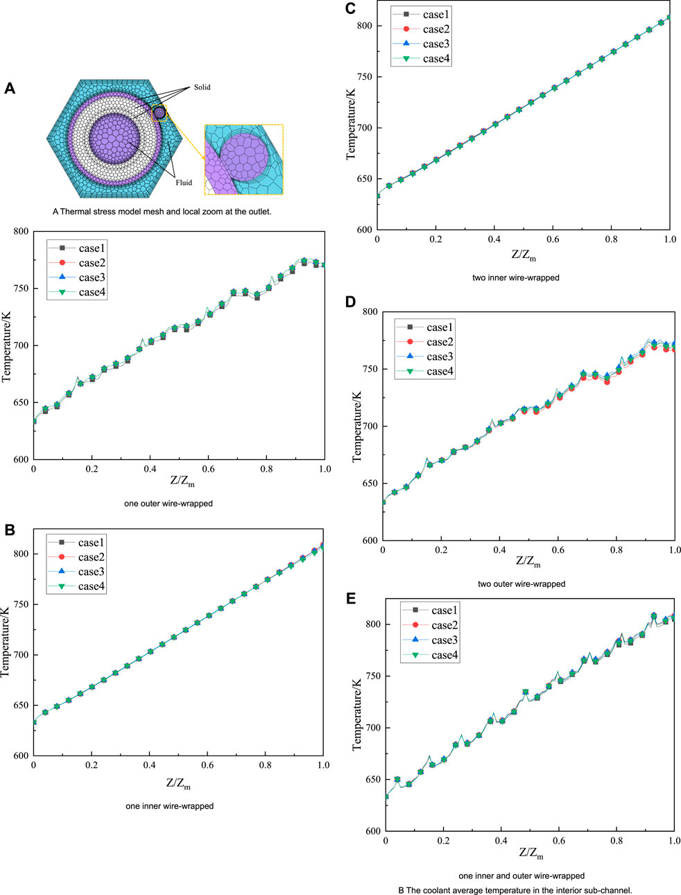
FIGURE 3. Mesh models and grid independence tests.
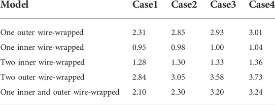
TABLE 2. Number of grids in different models (unit: million).
The equations that govern the steady-state sodium flow and heat transfer process in the annular fuel assembly are as follows.Continuity equation.
where u, v, w is the velocity component of fluid in x, y, z directions, and ρ is the density of the coolant.Momentum equation.
where τij is the component of the viscous stress, SMx, SMy, SMz is the momentum source term, and p is the pressure of the coolant.Energy equation.
where St is the viscous dissipation term, λ is the thermal conductivity of the coolant, T is the temperature of the coolant, and Cp is the heat capacity at constant pressure.
By solving the governing equations, the flow and heat transfer characteristics of the 7-pin annular fuel assembly with wire-wrapped are obtained in Table 3. The Standard k-ε model (Launder and Spalding, 1983), SST k-ω model (Menter, 1994), and Realizable k-ε model (Shih et al., 1995) are selected to compare the changes in the average temperature in the outlet of the interior sub-channel and pressure drop. The Y+ of the three turbulence models is 32.7 ≤ Y+≤76.4, Y+∼1, 52.4 ≤ Y+≤72.8. The coolant temperature and pressure drop in different turbulence models are similar. The maximum error range is 5.1%, which is an acceptable range. The majority of wall Y+ cells are below 100, so the high Reynolds k, ε turbulence is well-adapted to represent the turbulence existing in the fluid domain. Moreover, the calculation time of the Standard k-ε model is shortest compared to the others. To sum up, the Standard k-ε model is selected as the turbulence model that can yield optimal results in terms of efficiency and accuracy.
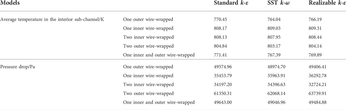
TABLE 3. Flow and heat transfer characteristics with different turbulence models.
As a double-equation model, the equation of turbulence dissipation rate is introduced based on the k equation. The double-equation is shown from Eqs. 4–7.
where
where k is turbulent kinetic energy, ε is the rate of dissipation of turbulent kinetic energy, σk is the turbulent Prandtl number for k, σε is the turbulent Prandtl number for ε, μ is molecular dynamic fluid viscosity, μt is turbulent viscosity, and Sij is the rate of deformation. The coefficients of the Standard k-ε model are as follows: C1e = 1.44, C2e = 1.92, Cμ = 0.09, σk = 1.0, and σε = 1.3.
The annular fuel bundle is set in the condition of steady-state in this research. It is assumed that the physical parameters of the annular fuel bundle are constant and a uniform heat source is available. Then the equation of thermal conductivity can be simplified as Eq. (8).
where T is the temperature of each part of the annular fuel, and Φ is the annular fuel heat source.
It is assumed that the material of the annular fuel bundle is uniform and homogeneous in calculating the thermal stress. The annular fuel bundle is approximated as an elastic object generating elastic strain because of the thermal stress with the following equations.
where ɛx, ɛy, ɛz is the strain in x, y, z direction, E is Young’s modulus, α is the thermal expansion coefficient, η is the Poisson’s ratio, σx, σy, σz is the stress in x, y, z direction, γ is the shear strain, and τ is the shear stress.
Liquid sodium metal is the coolant for the sodium-cooled fast reactor. It is assumed that the physical parameters of the coolant are not constant, including density, thermal conductivity, heat capacity at constant pressure, and dynamic viscosity. the relationship with temperature is shown in Table 4 (Cui et al., 2013). These parameters are imported in the form of UDF. The solid part, which mainly includes an annular fuel pellet, inner and outer cladding, and wire-wrapped, and its thermal properties and mechanical parameters are shown in Table 5.
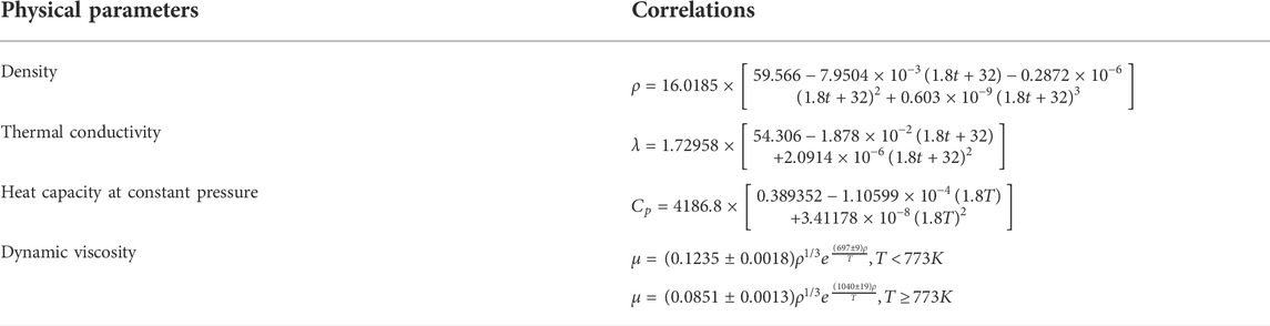
TABLE 4. The physical parameters of the fluid domain.
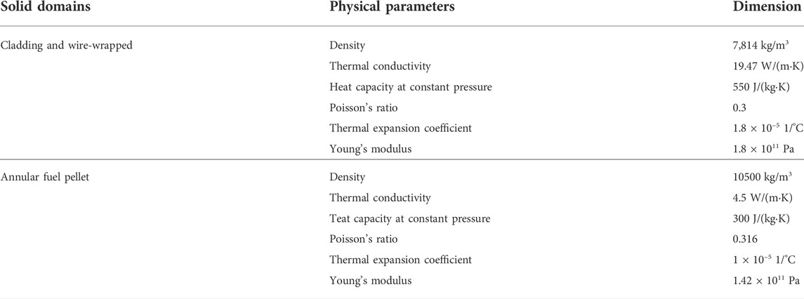
TABLE 5. The physical parameters of the solid domain.
According to the parameters of the Chinese Experimental Fast Reactor, the coolant inlet temperature is 633.15 K, and the inlet velocity is 3.5–8 m/s. The outlet is the pressure outlet, and the outlet’s static pressure is 0. The annular fuel rod is assumed to have the same heat flux on the inner and outer surfaces. The heat flux on the inner and outer surfaces are both 1.49 × 10⁶W/m3. The heat flux of the 7-pin bundle annular fuel assembly is set to the average surface heat flux density. The part of wire-wrapped is set to be without heat flux. The surface of the wrapper tube, the annular fuel rods surface, and the wire-wrapped surface are all no-slip surfaces. In this study, a pressure-based solver is used to calculate the discrete equations using the SIMPLE algorithm with the second-order upwind format. When the residuals of the momentum and turbulence equations reach 10–5 and the residuals of the energy equation reach 10–6, the calculation is finished.
In this research, the flow and heat transfer process in sub-channels of the 7-pin annular fuel assembly of sodium-cooled fast reactors is verified. Considering that the experiments of flow and heat exchange are based on the traditional fuel assembly with outer wire-wrapped, the model with one outer wire-wrapped is selected for verification in this research. The friction factor f is the most important dimensionless parameter to solve the pressure drop, and its value is related to the Reynolds number and the geometric structure of the fuel assembly, such as P/D and H/D. Its equation is as follows:
where ∆p is the pressure drop, L is the length of the coolant channel, v is the velocity of the coolant, and De is the equivalent diameter. Friction factor correlations, such as the Rehme model and the Cheng and Todreas simplified model, are widely used for a wire-wrapped fuel bundle. Each friction factor is calculated using the following correlations. The Rehme model and the Cheng and Todreas simplified model can be defined by Eqs 11–15, and the applicable range of models is shown in Table 6.
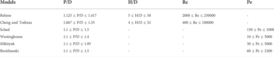
TABLE 6. Applicable range of models.
Rehme model (Rehme, 1973):
Rehme revised model.
where Re is the Reynolds number, Pwb is the wetted perimeter of the rod bundle, Pwt is the total wetted perimeter, and F is the square of the ratio of this effective velocity to the bundle average axial velocity. It is related to the geometry parameters.
Cheng and Todreas simplified model (Cheng and Todreas, 1986):
where CfT is the friction factor in turbulence.
The average heat transfer coefficient at the outlet is calculated as
where ∆T = Tc-Tf, Tc is the cladding temperature of all bundles at the outlet, Tf is the coolant temperature at the outlet, and q is the heat flux of the annular fuel rod. The Nusselt number is an important parameter to reflect the heat transfer characteristics in the fuel assembly, and its value is not only related to the Peclet number but also to the structural parameter P/D of the fuel assembly. These models can be defined by Eqs 17–20, and the applicable range of models is shown in Table 5.
Schad model (Kazimi and Carelli, 1976):
Westinghouse model (Kazimi and Carelli, 1976):
Mikityuk model (Mikityuk, 2009):
Borishanski model (Borishanskii et al., 1969):
where
Figure 4A depicts the comparison results of the CFD analysis results and the friction factor correlations. With the increase of the Reynolds number, the friction factor decreases gradually. Each friction factor correlation tends to be consistent with the change of the Reynolds number. Compared with correlations, the friction factor of the CFD analysis results in this study is smaller because when the total pressure drop of the core is constant, the pressure drop of the inner flow field will affect the pressure drop of the sub-channels and affect the variety of the friction factor f. The turbulence model has the smallest error with the Rehme revised model, and the errors with other correlations are also within an acceptable range.
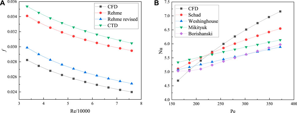
FIGURE 4. Comparison of the CFD analysis results (A) with the friction factor correlations and (B) with heat transfer correlations.
Figure 4B shows the comparison results of the CFD analysis results and the heat transfer correlations. With the increase of the Peclet number, the Nusselt number increases gradually. In terms of curve growth rate, the growth rate of the CFD analysis results is greater than that of the heat transfer correlations. The annular fuel assembly is developed in this research, so the heat exchange in the inner channels accounted for part of the share of the total heat flux in the annular fuel pellet, which will decrease the heat exchange in the sub-channels. Considering the various uncontrollable factors of the experiment itself and the difference between the Prandtl number of the liquid metal NaK or LBE used in the experiment and the Prandtl number of the liquid metal sodium used in the numerical simulation in this study, the errors are all within an acceptable range.
Figure 5 shows the serial number of the sub-channels and the inner flow field of the annular fuel assembly. Model (a) is taken as an example in Figure 5. The research selects the more representative sub-channels 4, 7, and 18 to analyze the change in the coolant temperature in different sub-channels. It is shown in Figure 6. Figure 6A shows the coolant temperature at the interior sub-channel 4. The coolant temperature increases gradually with the increase of Z/Zm. When the sub-channel is winding with wire-wrapped, there are different numbers of peaks in the distribution of temperature. The coolant in the interior sub-channel is mainly affected by the surrounding wire-wrapped from three annular fuel rods, so the number of the peak is disordered. The temperature of model (d) is bigger than that of model (a) and model (e). Figure 6B depicts the coolant temperature at the edge sub-channel 7. The temperature of the edge sub-channel is mainly affected by the two surrounding annular fuel rods, and the number of peaks in the temperature is more obvious than that of the interior sub-channel. On the whole, the temperature of the sub-channel in model (a) and model (e) are the highest. Figure 6C is the coolant temperature at the corner sub-channel 18. The temperature distribution of the corner sub-channel is mainly affected by the wire-wrapped of the annular fuel rod adjacent to it. Therefore, there are four peaks for model (a) and model (e). The number of wire-wrapped increases by one time in model (d), so the number of peaks has also doubled. The temperature of the five models is the highest in the interior sub-channel, followed by the corner sub-channel, and the lowest temperature is in the edge sub-channel. The temperature characteristics of model (a) and model (e) are better than others in the sub-channels. Figure 6D is the distribution of the coolant temperature in the inner flow field 1. The number of wire-wrapped is two in model (c), and the helical wire-wrapped mixes the coolant fully and strengthens the heat transfer between coolant and fuel bundles. The coolant outlet temperature is the lowest, which is about 742K. The number of wire-wrapped is only one of model (b) and model (e) in the inner flow field. The flow heat transfer effect of the wire-wrapped is inferior to the former slightly. The temperature of the two models is about 754K.
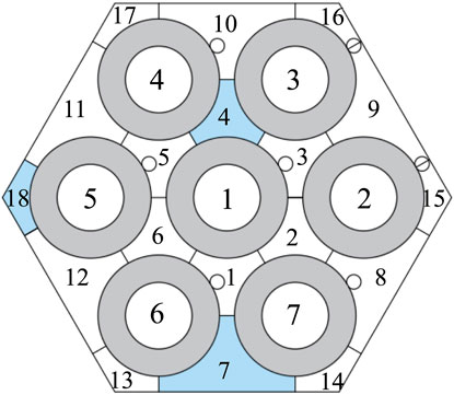
FIGURE 5. Serial number of sub-channels and inner flow field.
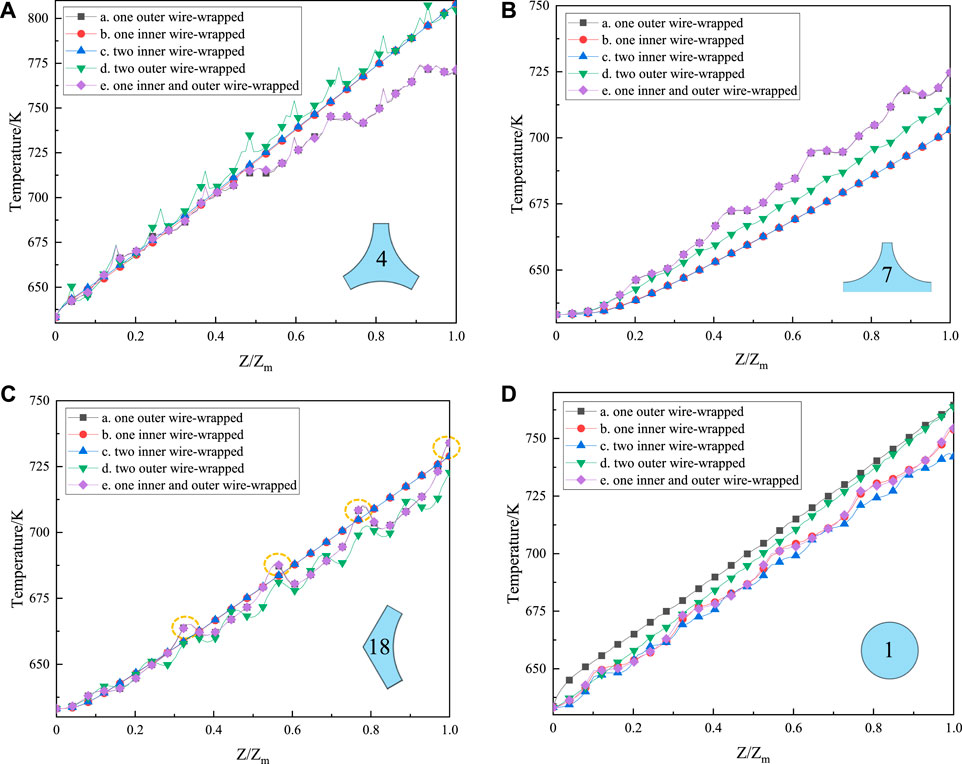
FIGURE 6. Distribution of temperature in the (A) interior sub-channel, (B) edge sub-channel, (C) corner sub-channel, and (D) inner flow field.
Figure 7 shows the temperature gradient of the five models. With the increase of Z/Zm, the temperature difference of each model increases gradually. The temperature difference in model (b) and model (c) is the largest, which is 105K. The temperature difference in model (a) and model (e) is the smallest, only 46K. The temperature difference in model (d) is 90K. It is not difficult to find from the above data that the key to affecting the temperature difference is the temperature of the three sub-channels. The outer wire-wrapped reduces the coolant temperature difference and flattens the coolant outlet temperature difference, and makes the coolant outlet temperature more uniform. The effect of flattening the temperature difference in model (a) and model (e) is better than that in model (d). When the ratio of the rod pitch to rod diameter (P/D) is constant, the number of the outer wire-wrapped increases, which will cause overlap between the wire-wrapped and wire-wrapped from the adjacent fuel rod. It may cause the coolant flow channel and poor heat transfer. Figure 8 is the overlap of wire-wrapped in the model of one inner and outer wire-wrapped. Considering the sub-channels, inner flow field, and temperature difference, the temperature field characteristics of one inner and outer wire-wrapped (model e) are better than those of others.
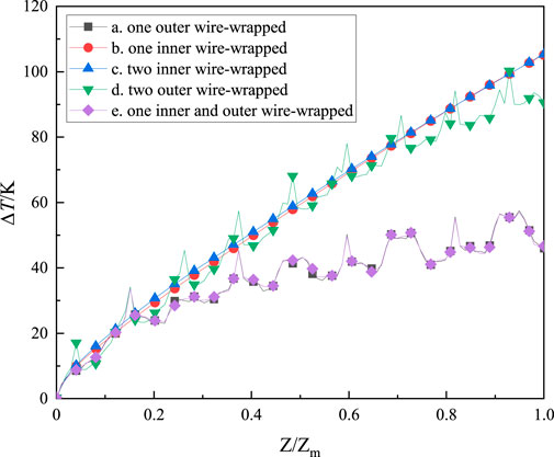
FIGURE 7. Temperature difference in different cross-sections.
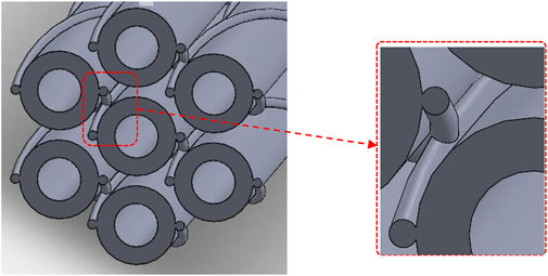
FIGURE 8. Overlap of wire-wrapped in the model of model (e).
Figure 9 is the velocity vector of the transverse velocity of cross-session for the five models. It can be seen from the figure that the transverse velocity of the five models is 1.74 m/s, 0.54 m/s, 0.62 m/s, 1.65 m/s, and 1.74 m/s, respectively. The transverse velocity of coolant in the sub-channels is about three times that of in the inner flow field. The sub-channels of the annular fuel assembly can be considered a whole, and the coolant can flow from one sub-channel to another sub-channel. Therefore, the flow of the coolant in the sub-channels is affected by all the wire-wrapped twined bundles. Every inner flow field is an independent individual. The inner flow fields do not affect each other. The transverse velocity of model (b) is smaller than that of model (c). It may be that because of the increase of the number of wire-wrapped, the direction of the coolant flow is hindered by the wire-wrapped. The velocity components in the x and y directions increase, which is behaved as an increase in the transverse velocity. From the perspective of the inner flow field, the increase in the number of wire-wrapped leads to an increase in transverse velocity. Due to the number of wire-wrapped being two in model (d), there will be an overlap between the wire-wrapped and the wire-wrapped adjacent rod bundles. The flow of the coolant is blocked, the velocity of the coolant decreases, and the transverse velocity also decreases. Thus, the effect of model (a) and model (e) is better than that of model (d). The number of wire-wrapped is not as good as possible from the perspective of sub-channels. Overall, the transverse velocity of one inner and outer wire-wrapped (model e) is better than that of others.
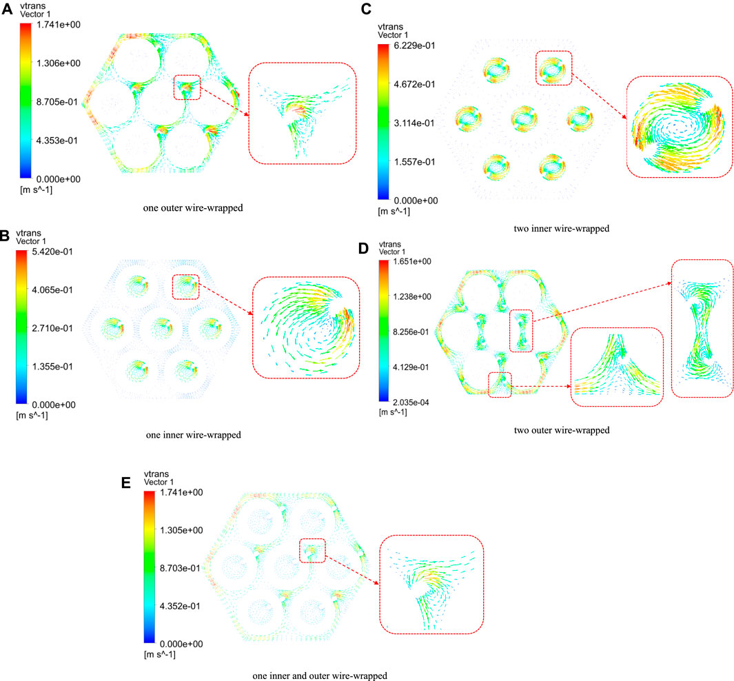
FIGURE 9. Velocity vector of the transverse velocity of cross-session with different models.
It can be seen from the local enlarged vector of the transverse velocity in Figure 9 that the flow of coolant is blocked when the coolant encounters the wire-wrapped during the flow of the coolant. The flow area of the coolant decreases, and the advancing direction is hindered by the wire-wrapped. The coolant gathers in a narrow position between the annular fuel rod and the wire-wrapped. It appears that the transverse velocity is greatest at the narrow location between the wire-wrapped and the annular fuel rod. Figure 9A depicts the local enlarged vector of the transverse velocity that the flow of the coolant in the interior sub-channel is affected by the wire-wrapped from three directions of the adjacent three annular fuel rods, and a vortex appears at the gathering position.
Figure 10 shows the pressure drop of the coolant in different sub-channels and inner flow fields. With the increase of Z/Zm, the pressure drop of the coolant decreases gradually, and it is 0 Pa at the outlet. The pressure drop of the sub-channels is all larger than the pressure drop of the inner flow field. Figure 10A–C are the coolant pressure drop at the sub-channels 4, 7, and 18. There is only one wire-wrapped in the sub-channels of models (a) and (e). The existence of the wire-wrapped in models (a), (d), and (e) causes the coolant pressure drop to increase in the sub-channel. The pressure drop is the largest in model (d), which reaches 6.1 × 10⁴Pa. In addition, the pressure drop of the coolant exhibits a periodic decrease during the wire-wrapped outer. There are four peaks on the pressure drop curve. This is because the winding position of the wire-wrapped has an influence on the coolant flow. Therefore, the flow velocity of the coolant increases, and the pressure drop decreases. This phenomenon disappears when the coolant flows through the wire-wrapped.
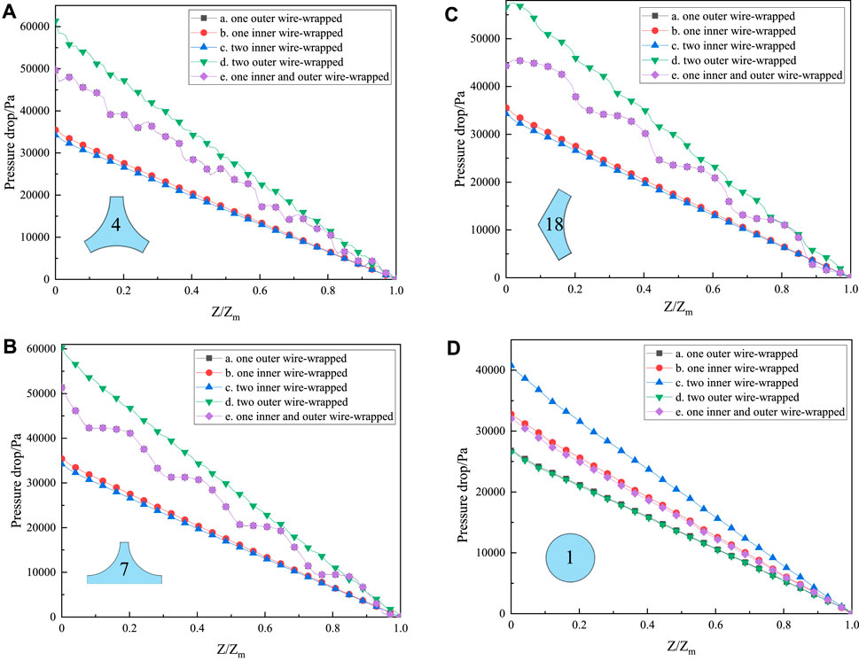
FIGURE 10. Distribution of pressure drop in the (A) interior sub-channel, (B) edge sub-channel, (C) corner sub-channel, and (D) inner flow field.
Figure 10D depicts the pressure drop of the coolant in the inner flow field. The coolant pressure drop decreases linearly as Z/Zm increases. The main factor that affects the pressure drop in the inner flow field is whether the wire-wrapped in the inner flow field. The number of wire-wrapped is two in model (c), so the pressure drop is the largest, which is reach to 4.1 × 10⁴Pa. In addition, the pressure drop of model (b) and model (e) is in the middle, and the pressure drop is 3.2 × 10⁴Pa, which is about 22% smaller than the maximum pressure drop. No matter the sub-channels or the inner flow field, the increase in the number of wire-wrapped will cause an increase in the pressure drop. The increase in pressure drop may have an impact on the normal operating conditions of the core. Overall, the pressure drop of one inner and outer wire-wrapped (model e) is better than that of others. According to the design criteria of sodium-cooled fast reactors, the pressure drops of the above five models are all within their safety margins and meet the design criteria.
The fuel pellets will have a visible temperature gradient from the center to the surface during the operation of the annular fuel rod in the reactor. The annular fuel rod will generate thermal stress by the influence of the temperature gradient, which leads to the deformation of the annular fuel rod. As the first shelter to tolerate the deformation of the annular fuel rod, it is very important to study the deformation and thermal stress of the annular fuel rod and the cladding. Figure 11 is the cross-section of the thermal stress model. At the same time, a line in θ = 45° is selected to extract the data of temperature and thermal stress of coolant, cladding, and annular fuel rod in radial.
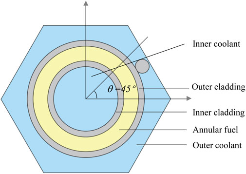
FIGURE 11. Cross-section of the thermal stress model.
Figure 12 depicts the radial temperature of the annular fuel rod and cladding along the line of θ = 45° with different Z/Zm. Along the X-axial, from left to right, are the inner coolant, inner cladding, annular fuel rod, outer cladding, and outer coolant, respectively. The thickness of the inner and outer claddings is 4 mm. Here, Z is the Z-coordinate, and Zm is the total length of the annular fuel rod. With the increase of Z/Zm, the temperature of both the fluid domain and the solid domain increases, and the temperature at the outlet (Z/Zm = 1) is the highest. Overall, the temperature of the annular fuel rod is high in the middle and low on both sides. At the radial midpoint of the fuel rod (R = 3.1 mm), the annular fuel rod temperature is the highest, reaching about 830K. The heat flux of the annular fuel rod is transferred to the inner and outer claddings on both sides through the method of heat conduction. Sufficient heat transfer can achieve the purpose of taking away the heat of the annular fuel rod by the inner and outer claddings and the coolant. The temperature on the left side of the symmetrical position (R = 3.1 mm) is higher than the temperature on the right side.
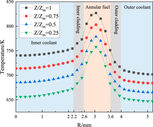
FIGURE 12. Distribution of temperature of the thermal stress model.
Figure 13 is the distribution of temperature with the inner and outer flow fields of the annular fuel rod. With the increase of Z/Zm, the temperature of the inner and outer flow fields increases gradually. In addition, the temperature difference larger between the inner and outer flow fields increases with the increase of Z/Zm. The maximum temperature difference is about 40K on the coolant outlet (Z/Zm = 1). This may be caused by the fact that the surface area of the fuel pellet per unit of coolant flow which acts as the area for heat transfer from the fuel to the coolant at the inner flow field is larger than that of the outer flow field. In addition, the annular fuel rod is positioned by the wire-wrapped, and the spiral method of the wire-wrapped has an impact on the flow of the coolant in the outer flow field. Therefore, lower temperature in the outer flow field than in the inner. There are four peaks in the temperature curve. There is no wire-wrapped effect in the inner flow field, so the temperature rises linearly.
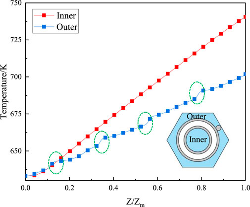
FIGURE 13. Distribution of temperature with inner and outer.
Figure 14 indicates the total deformation of the solid domain along the Z-axial. The total deformation of the middle part (Z = 0.24 m) of the solid domain is the largest and about 79 μm. Due to the fixing effect of the structure on both sides of the annular fuel rod, the displacement of both sides of the annular fuel rod and the inner and outer claddings is the smallest. Overall, the deformation of the whole solid domain is characterized by small at both slides and large in the middle. The total displacement distribution curve is similar to the shape of a parabola. Excessive displacement can affect the safety of the annular fuel rod and even the whole core. Swelling and cracking of the cladding will happen. Therefore, the total deformation of the annular fuel rod is considered an important parameter. Figure 15 shows the stress distribution of the annular fuel rod and claddings of the inner and outer. The stress variation in the solid domain is mainly along the radial direction. The axial variation tends to be consistent. The stress in the cladding is about 1.75 times the stress in the annular fuel rod, and the stress in the inner cladding is higher than that in the outer cladding.
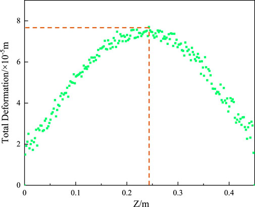
FIGURE 14. Total deformation of the solid domain.

FIGURE 15. Stress of solid domain.
Thermal-hydraulic characteristics of the 7-pin annular fuel assembly with the inner and outer wire-wrapped are investigated in this research. The flow, heat transfer, and mechanical properties are analyzed, and the conclusions are as follows.
The temperature of three sub-channels is the key that influences the temperature characteristics. The wire-wrapped reduces the coolant temperature gradient, flattens the coolant outlet temperature, and makes the coolant outlet temperature more uniform. The increase in the number of wire-wrapped is not better, and the geometry of the annular fuel assembly should be fully considered. Considering the sub-channels, inner flow field, and temperature difference, the temperature field characteristics of one inner and outer wire-wrapped (model e) are better than those of others.
The transverse velocity of coolant in the sub-channels is about three times that of in the inner flow field. From the perspective of the inner flow field, the increase in the number of wire-wrapped leads to an increase in transverse velocity. The number of wire-wrapped is not as good as possible from the perspective of sub-channels. The transverse velocity of one inner and outer wire-wrapped (model e) is better than that of others.
The pressure drop of the sub-channels is greater than the pressure drop of the inner flow field. No matter the sub-channels or the inner flow field, the increase in the number of wire-wrapped will cause an increase in the pressure drop. The pressure drop of one inner and outer wire-wrapped (model e) is better than that of others. In conclusion, the thermal-hydraulic properties of one inner and outer wire-wrapped (model e) are better than those of other models.
The temperature of the annular fuel rod is high in the middle and low on both sides. The total deformation of the middle part of the solid domain is the largest and about 79 μm. The stress variation in the solid domain is mainly along the radial direction. The axial variation tends to be consistent. The stress in the cladding is about 1.75 times the stress in the annular fuel rod, and the stress in the inner cladding is higher than that in the outer cladding because the inner cladding surface area is less than the outer cladding surface area. These findings provide a reference for the optimization design of the fuel assembly. In future work, special conditions or the effect of variable conditions on the fatigue life of wire-wrapped assemblies is yet to be investigated.
The original contributions presented in the study are included in the article/Supplementary Material; further inquiries can be directed to the corresponding author.
YG has written and organized the structure of the manuscript and has performed some of the calculations presented in the manuscript. BZ and XY have performed some of the calculations in the manuscript. XD, YZ, and CT have given some advice about the manuscript.
This work is supported by the National Natural Science Foundation of China (Nos. 12175116 and 11805112). The authors would like to show their great appreciation to other members of the team for their support and contribution to this research.
The authors declare that the research was conducted in the absence of any commercial or financial relationships that could be construed as a potential conflict of interest.
All claims expressed in this article are solely those of the authors and do not necessarily represent those of their affiliated organizations, or those of the publisher, the editors, and the reviewers. Any product that may be evaluated in this article, or claim that may be made by its manufacturer, is not guaranteed or endorsed by the publisher.
Bertocchi, F., Rohde, M., and Kloosterman, J. (2019). Understanding migratory flow caused by helicoid wire spacers in rod bundles: An experimental and theoretical study. Int. J. Heat Fluid Flow 80, 108491. doi:10.1016/j.ijheatfluidflow.2019.108491
Bieder, U., Uitslag-Doolaard, H., and Mikuž, B. (2021). Investigation of pressure loss and velocity distribution in fuel assemblies with wire-wrapped rods by using RANS and LES with wall functions. Ann. Nucl. Energy 152, 108025. doi:10.1016/j.anucene.2020.108025
Borishanskii, V., Gotovskii, M., and Firsova, E. (1969). Heat transfer to liquid metals in longitudinally wetted bundles of rods. A. T. Energy 27, 1347–1350. doi:10.1007/BF01118660
Chen, J., Zhang, D. L., Song, P., Wang, X. A., Wang, S. B., Liang, Y., et al. (2018a). CFD investigation on thermal-hydraulic behaviors of a wire-wrapped fuel subassembly for sodium-cooled fast reactor. Ann. Nucl. Energy 113, 256–269. doi:10.1016/j.anucene.2017.11.023
Chen, S. K., Chen, Y. M., and Todreas, N. E. (2018b). The upgraded Cheng and Todreas correlation for pressure drop in hexagonal wire-wrapped rod bundles. Nucl. Eng. Des. 335, 356–373. doi:10.1016/j.nucengdes.2018.05.010
Cheng, S.-K., and Todreas, N. E. (1986). Hydrodynamic models and correlations for bare and wire-wrapped hexagonal rod bundles - bundle friction factors, subchannel friction factors and mixing parameters. Nucl. Eng. Des. 92, 227–251. doi:10.1016/0029-5493(86)90249-9
Choi, S. K., Choi, I. K., Nam, H. Y., Choi, J. H., and Choi, H. K. (2003). Measurement of pressure drop in a full-scale fuel assembly of a liquid metal reactor. J. Press. Vessel Technol. 125, 233–238. doi:10.1115/1.1565076
Chun, M.-H., and Seo, K.-W. (2001). An experimental study and assessment of existing friction factor correlations for wire-wrapped fuel assemblies. Ann. Nucl. Energy 28, 1683–1695. doi:10.1016/S0306-4549(01)00023-8
Cui, M., Guo, Y., and Zhang, Z. (2013). Transient simulation code development of primary coolant system of Chinese Experimental Fast Reactor. Ann. Nucl. Energy 53, 158–169. doi:10.1016/j.anucene.2012.09.022
El-Sahlamy, N., Hassan, M., and Khedr, A. (2020). Comparison between standard solid fuel and a new annular fuel performance in the core of a PWR. Kerntechnik 85, 161–168. doi:10.3139/124.190020
Engel, F. C., Markley, R. A., and Bishop, A. A. (2017). Laminar, transition, and turbulent parallel flow pressure drop across wire-wrap-spaced rod bundles. Nucl. Sci. Eng. 69, 290–296. doi:10.13182/nse80-a2012710.13182/nse79-a20618
Feng, D., Morra, P., Sundaram, R., Lee, W.-J., Saha, P., Hejzlar, P., et al. (2007). Safety analysis of high-power-density annular fuel for PWRs. Nucl. Technol. 160, 45–62. doi:10.13182/NT07-A3883
Gajapathy, R., Velusamy, K., Selvaraj, P., and Chellapandi, P. (2015). CFD investigation of effect of helical wire-wrap parameters on the thermal hydraulic performance of 217 fuel pin bundle. Ann. Nucl. Energy 77, 498–513. doi:10.1016/j.anucene.2014.10.038
Hou, Y., Wang, L., Wang, M., Zhang, K., Zhang, X., Hu, W., et al. (2019). Experimental study of liquid sodium flow and heat transfer characteristics along a hexagonal 7-rod bundle. Appl. Therm. Eng. 149, 578–587. doi:10.1016/j.applthermaleng.2018.12.043
Kazimi, M., and Carelli, M. (1976). Clinch river breeder reactor plant. Heat transfer correlation for analysis of CRBRP assemblies. Madison, PA (United States): Westinghouse Electric Corp.Advanced Reactors Div.
Kazimi, M. S., Hejzlar, P., Carpenter, D., Feng, D., Kohse, G., Lee, W. J., et al. (2006). High performance fuel design for next generation PWRs.
Kwon, Y., Yang, Y., Kim, J., and Kwon, S. (2013). A study on the flow characteristics in an annular type fuel pellet of PWR. J. Mech. Sci. Technol. 27, 257–261. doi:10.1007/s12206-012-1205-x
Lahoda, E., Mazzoccoli, J., and Beccherle, J. (2007). High-power-density annular fuel for pressurized water reactors: Manufacturing costs and economic benefits. Nucl. Technol. 160, 112–134. doi:10.13182/NT07-A3887
Launder, B. E., and Spalding, D. B. (1983). “The numerical computation of turbulent flows,” in Numerical prediction of flow, heat transfer, turbulence and combustion (Elsevier), 96–116. doi:10.1016/b978-0-08-030937-8.50016-7
Liang, Y., Zhang, D., Chen, Y., Zhang, K., Tian, W., Qiu, S., et al. (2020). An experiment study of pressure drop and flow distribution in subchannels of a 37-pin wire-wrapped rod bundle. Appl. Therm. Eng. 174, 115283. doi:10.1016/j.applthermaleng.2020.115283
Liu, L., Wang, S., and Bai, B. (2017). Thermal-hydraulic comparisons of 19-pin rod bundles with four circular and trapezoid shaped wire wraps. Nucl. Eng. Des. 318, 213–230. doi:10.1016/j.nucengdes.2017.04.017
Menter, F. R. (1994). Two-equation eddy-viscosity turbulence models for engineering applications. AIAA J. 32, 1598–1605. doi:10.2514/3.12149
Mikityuk, K. (2009). Heat transfer to liquid metal: Review of data and correlations for tube bundles. Nucl. Eng. Des. 239, 680–687. doi:10.1016/j.nucengdes.2008.12.014
Natesan, K., Sundararajan, T., Narasimhan, A., and Velusamy, K. (2010). Turbulent flow simulation in a wire-wrap rod bundle of an LMFBR. Nucl. Eng. Des. 240, 1063–1072. doi:10.1016/j.nucengdes.2009.12.025
Naveen Raj, M. N., and Velusamy, K. (2016). Characterization of velocity and temperature fields in a 217 pin wire wrapped fuel bundle of sodium cooled fast reactor. Ann. Nucl. Energy 87, 331–349. doi:10.1016/j.anucene.2015.09.008
Novendstern, E. (1972). Turbulent flow pressure drop model for fuel rod assemblies utilizing a helical wire-wrap spacer system. Nucl. Eng. Des. 22, 28–42. doi:10.1016/0029-5493(72)90059-3
Pacio, J., Chen, S.-K., Chen, Y.-M., and Todreas, N. (2022). Analysis of pressure losses and flow distribution in wire-wrapped hexagonal rod bundles for licensing. Part I: The Pacio-Chen-Todreas Detailed model (PCTD). Nucl. Eng. Des. 388, 111607. doi:10.1016/j.nucengdes.2021.111607
Pacio, J., Daubner, M., Fellmoser, F., Litfin, K., and Wetzel, T. (2016). Experimental study of heavy-liquid metal (LBE) flow and heat transfer along a hexagonal 19-rod bundle with wire spacers. Nucl. Eng. Des. 301, 111–127. doi:10.1016/j.nucengdes.2016.03.003
Rehme, K. (1973). Pressure drop correlations for fuel element spacers. Nucl. Technol. 17, 15–23. doi:10.13182/NT73-A31250
Rowinski, M. K., White, T. J., and Zhao, J. (2015). Innovative model of annular fuel design for lead-cooled fast reactors. Prog. Nucl. Energy 83, 270–282. doi:10.1016/j.pnucene.2015.04.002
Shih, T.-H., Liou, W. W., Shabbir, A., Yang, Z., and Zhu, J. (1995). A new k-ϵ eddy viscosity model for high Reynolds number turbulent flows. Comput. fluids 24, 227–238. doi:10.1016/0045-7930(94)00032-T
Shin, C.-H., Chun, T.-H., and Oh, D.-S. (2012). Thermal hydraulic performance assessment of dual-cooled annular nuclear fuel for OPR-1000. Nucl. Eng. Des. 243, 291–300. doi:10.1016/j.nucengdes.2011.12.010
Song, M. S., Jeong, J. H., and Kim, E. S. (2019). Numerical investigation on vortex behavior in wire-wrapped fuel assembly for a sodium fast reactor. Nucl. Eng. Technol. 51, 665–675. doi:10.1016/j.net.2018.12.012
Wang, H., Wang, S., and Lu, D. (2020). PIV measurements of the cross flow induced by a wrapped wire spacer. Ann. Nucl. Energy 146, 107634. doi:10.1016/j.anucene.2020.107634
Wang, X., and Cheng, X. (2018). Analysis of inter-channel sweeping flow in wire wrapped 19-rod bundle. Nucl. Eng. Des. 333, 115–121. doi:10.1016/j.nucengdes.2018.04.008
Xu, Z., Liu, Y., and Wang, B. (2020). Simulation and optimization design of fuel rod in pressurized water fuel assemblies. Nucl. Eng. Des. 370, 110856. doi:10.1016/j.nucengdes.2020.110856
Zaidabadi, M., Ansarifar, G., and Esteki, M. (2017). Thermal hydraulic analysis of VVER-1000 nuclear reactor with dual-cooled annular fuel using K–ω SST Turbulence model. Ann. Nucl. Energy 101, 118–127. doi:10.1016/j.anucene.2016.09.027
Keywords: annular fuel assembly, sodium-cooled fast reactor, inner and outer wire-wrapped, thermal stress, computational fluid dynamics
Citation: Guo Y, Zhang B, Yuan X, Du X, Zhang Y and Tan C (2022) Thermal-hydraulic characteristics in inner and outer wire-wrapped for a fast reactor annular fuel assembly. Front. Energy Res. 10:973390. doi: 10.3389/fenrg.2022.973390
Received: 20 June 2022; Accepted: 01 September 2022;
Published: 26 September 2022.
Edited by:
Shripad T Revankar, Purdue University, United StatesReviewed by:
Jinbiao Xiong, Shanghai Jiao Tong University, ChinaCopyright © 2022 Guo, Zhang, Yuan, Du, Zhang and Tan. This is an open-access article distributed under the terms of the Creative Commons Attribution License (CC BY). The use, distribution or reproduction in other forums is permitted, provided the original author(s) and the copyright owner(s) are credited and that the original publication in this journal is cited, in accordance with accepted academic practice. No use, distribution or reproduction is permitted which does not comply with these terms.
*Correspondence: Xianbao Yuan, dmVyb25hMTIwNkAxNjMuY29t
Disclaimer: All claims expressed in this article are solely those of the authors and do not necessarily represent those of their affiliated organizations, or those of the publisher, the editors and the reviewers. Any product that may be evaluated in this article or claim that may be made by its manufacturer is not guaranteed or endorsed by the publisher.
Research integrity at Frontiers
Learn more about the work of our research integrity team to safeguard the quality of each article we publish.