
95% of researchers rate our articles as excellent or good
Learn more about the work of our research integrity team to safeguard the quality of each article we publish.
Find out more
ORIGINAL RESEARCH article
Front. Energy Res. , 09 November 2022
Sec. Smart Grids
Volume 10 - 2022 | https://doi.org/10.3389/fenrg.2022.972089
This article is part of the Research Topic Optimal Energy Management for Electric Vehicles (EVs) by the interface of Vehicle to Grid (V2G), Grid to Vehicle (G2V) and Smart Grid Scheduling View all 7 articles
 Kambhampati Venkata Govardhan Rao1
 Malligunta Kiran Kumar1*
 B. Srikanth Goud2
 Mohit Bajaj3
 Mohamad Abou Houran4
 Salah Kamel5*
Electric vehicles are projected to play an important role in the present and ensuing transportation as global environmental and energy issues become more serious. Looking into the growing popularity of electric vehicles, we need to pay even more attention to battery energy storage systems. Electric vehicles in the traditional sense rely on a battery to provide electricity. Influential requirements (acceleration and braking) will deteriorate the battery, or it may not be feasible to use it at all in some instances, due to the battery’s compactness. This paper proposes a Bidirectional DC/DC Converter topology and investigates its operation modes. The proposed converter can be used in hybrid electric vehicles. Hybrid electric vehicles use this converter type to connect a primary battery (ES1), an extra battery (ES2), and an adjustable voltage bus. Both step-up (i.e., Dual-source low-voltage powering mode) and step-down (i.e., energy-regenerating high-voltage dc-link mode) modes of operation are possible with the proposed converter, allowing bidirectional power flow. Furthermore, the model can handle the flow of electricity between any two low-voltage sources. For the proposed Bidirectional DC/DC Converter, two ways of power transmission, circuit design, and operation modes are analyzed. A MATLAB-Simulink model of the proposed, and the system is developed based on a Digital Signal Processor flow chart, and the results of the simulation as well as the performance of the system are discussed.
Changes in vehicle technology have been prompted by a shift in bias and the depletion of power sources. Advanced technology is being studied for future vehicle applications. Fuel-cell vehicle/hybrid electric vehicles (FCV/HEV) are one of these applications that is both efficient and promising. The ideal torque-speed pattern for an electric propulsion system was previously determined using vehicle dynamics (Ehsani et al., 1997). Geometries for various cars, such as HEVs, FCVs, and greater e-mobility (Emadi et al., 2005), as well as separate but equal power electronics aggressive treatment in modern vehicle power systems to meet huge vehicle loads (Emadi et al., 2006). The required full load power can be consumed with the help of a battery, fuel cell stack, and ultracapacitors using two energy management algorithms (Schaltz et al., 2009). HEV and FC vehicle research refer to energy monitoring systems and structures, information on various HEVs and Plug-in HEVs (PHEVs), and the effect of FC efficiency on control techniques (Thounthong et al., 2009; Chan et al., 2010). This research looked at battery, unmanned, and FC-based automation. Some of the hybrid ESSs (multi-device storage systems) were also investigated (Khaligh and Li, 2010). Batteries, electric motors, and power electronic systems are employed to establish the necessary current balance (Rajashekara, 2013). A dc/dc converter featuring a slew of interlocking features was devised by the team. A dc/dc converter can improve the voltage conversion efficiency for EV and DC microgrid systems (Lai et al., 2015). EV batteries require a bidirectional DC to DC converter (BDCC) to accept high voltage power from a microgrid (Lai, 2016). Primary battery storage is frequently used to activate the FC and to power the propel motor in FCV systems. Peak power is delivered as the vehicle speeds up, which helps to compensate for the FC. Super-capacitors (SCs) and other high-density components help to reduce the maximum energy non-linearities that can occur during acceleration and braking (Moreno et al., 2006). SCs may be able to store regenerated energy during slowdown and then release it to generate more electricity during propulsion. The FC stack and storage batteries get more usage out of their FCV systems with high-power density SCs (Bauman and Kazerani, 2008).
In this paper, a unique BDCC design for FCV/HEV power systems is developed using a synchronous buck-boost circuit (Jiang et al., 2013) and an interleaved voltage-double architecture (Jung et al., 2013). There are two primary methods of operation: low-voltage power from two sources and high-voltage dc-bus energy regeneration (Wu et al., 2013). The recommended converter can switch between two low-voltage sources in a buck/boost mode, autonomously. In contrast to (Farhangi and Toliyat, 2015), provided a topology that only represents a particular concept (Lin and Chao, 2013). The primary features of the recommended converter are as follows:
• Connects several dc sources with varied voltage ranges.
• Two low-voltage sources are linked via an ac bus and a voltage regulator.
• Reducing the stress on switch currents while increasing the static voltage gain.
Provides large voltage differences between the high and low ports, as well as a high duty cycle.
The primary power source is a low-voltage FC stack with SCs connected to FCs in parallel and is depicted in Figure 1 of a standard (FCV/HEV) (Ehsani et al., 2009) power system. The propulsion motor can be powered by the dc-bus voltage that is generated by the driving inverter’s dc/dc power components (Haihua and Khambadkone, 2008). Even though the vehicle work to expand design based on ES2, ES1 is utilized as the primary energy storage system medium for peak power generation. It is used to connect the operational inverter’s dc bus to dual-energy storage. Several BDCC switches have been distributed to supply particular voltages to loads while controlling power flow between several sources (Tao et al., 2008). Overall cost, mass, and power use are all reduced. The two categories of BDCCs are isolated and non-isolated BDCCs (Bhattacharya et al., 2009).
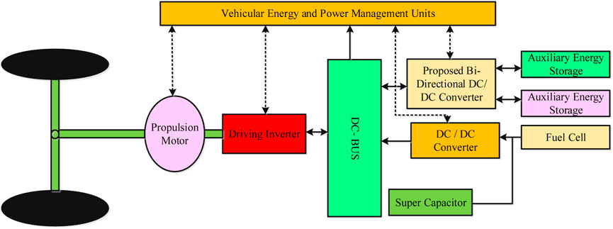
FIGURE 1. Schematic structure for an FCV/HEV power system.
Electrochemical cells are isolated from one another by using high-frequency transformers in isolated converters All other isolated multiport BDCC topologies, including hop, half or full-bridge circuits, double-active bridges, and other variations, have also been investigated (Krishnaswami and Mohan, 2009). BDCCs that are not isolated have a greater EV success rate than isolated BDCCs (Liu and Chen, 2009). Renewable energy sources, a battery storage system, and a load can all be powered simultaneously via the three-port non-isolated MIMO converter, which utilizes all these converter types. The three double-input converters developed in (Gummi and Ferdowsi, 2010) use a single-pole triple-throw switch and only one inductor. (Zhao et al., 2012). described a modular non-isolated dc MIMO converter. The fundamental boost circuit was improved and integrated into this converter, which is used to hybridize sustainable energy sources in electric vehicles.
Some of the most important references with their observation methods are listed in Table 1.
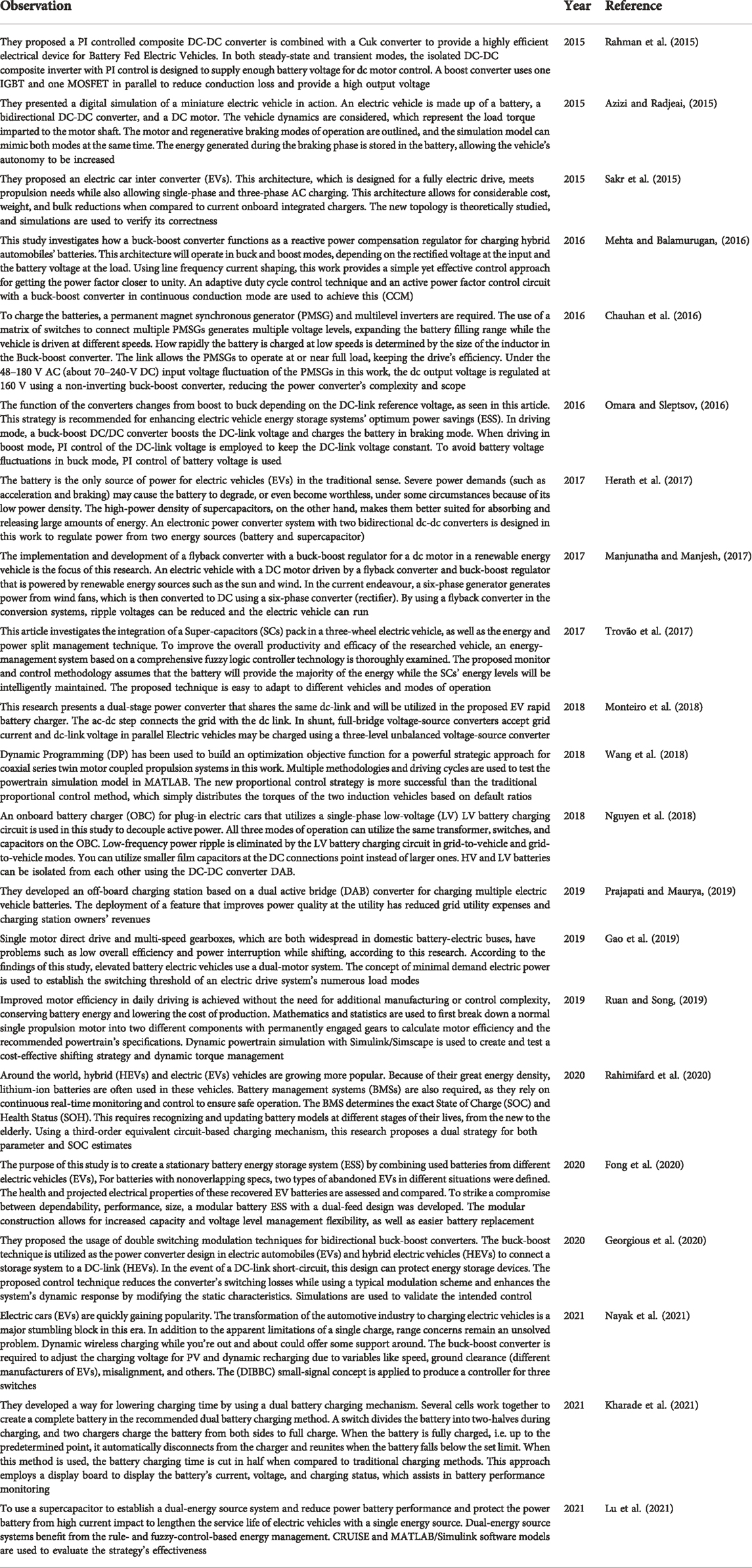
TABLE 1. Literature survey.
The remaining part of the paper is laid out as follows. The proposed BDCC’s structure, as well as its operation modes, are explored and detailed in section 3. Section 4 describes the converter’s control system, and Section 5 depicts the simulation results for various operation modes. Conclusions and future work are presented at the end of the paper.
The elevated dc bus voltage (VH, VES1, and VES2), basic stored energy, and supplemental energy storage are shown in Figure 2 of the BDCC design (ES2), The current circuits of ES1 and ES2 are turned on and off by two bidirectional power switches (S, SES1 and SES2) in the converter’s layout (Kharade et al., 2021).
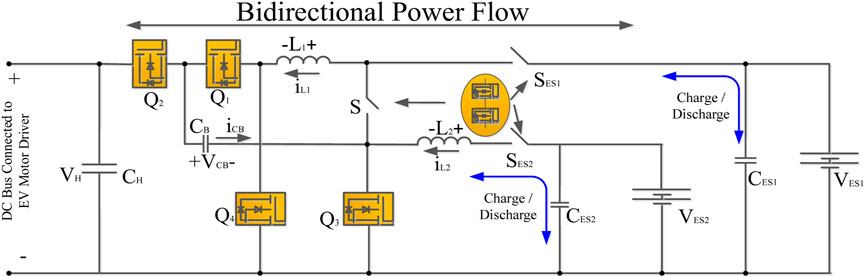
FIGURE 2. BDCC proposed architecture including dual battery storage.
A charge-pump capacitor (CB) with four active switches (Q1, Q2, Q3, Q4) and two-phase inductors (L1, L2) improves the dynamic voltage gain between two low-voltage dual sources (VES1, VES2) and the higher-voltage bus (VH). By adding an extra CB, switching voltage stress is reduced, and a high duty ratio is no longer required.
Table 2 depicts all the conductivity levels of such power devices involved in each working model to demonstrate the concept for the proposed converter (Moradisizkoohi et al., 2019). As a result, the four functional states are illustrated as follows to aid comprehension.
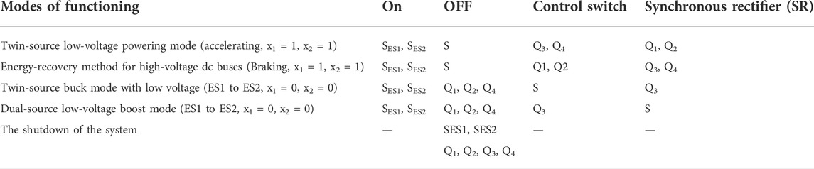
TABLE 2. Devices’ current state of operation for various operating modes.
Stable patterns for the converter are shown in Figure 3, for dual-source low-voltage powering, Figure 3A. In the circuit, SES1, and SES2 are activated while controller S is deactivated. The VES1 and VES2 provide power to loads as well as a dc bus. The controllers Q3 and Q4 switch at a 180° phase difference in this mode, while the remaining Q1 and Q2 act as synchronous rectifiers (SR).
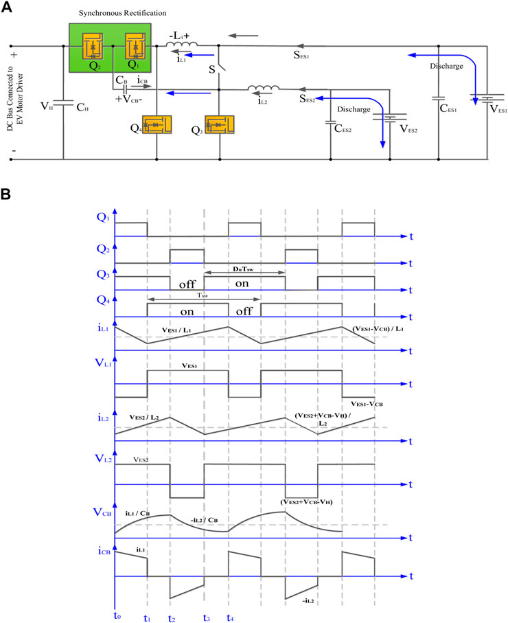
FIGURE 3. The proposed BDCC’s dual-source low-voltage powering mode: (A) Circuit design (B) Stable pattern.
More than half of the duty ratio allows access to four circuit levels as indicated in Typical Patterns Figure 3B. (As depicted in Figure 4). According to the state of the BDCC and the active switches, dual-source low-voltage powering mode operation can be described as follows.
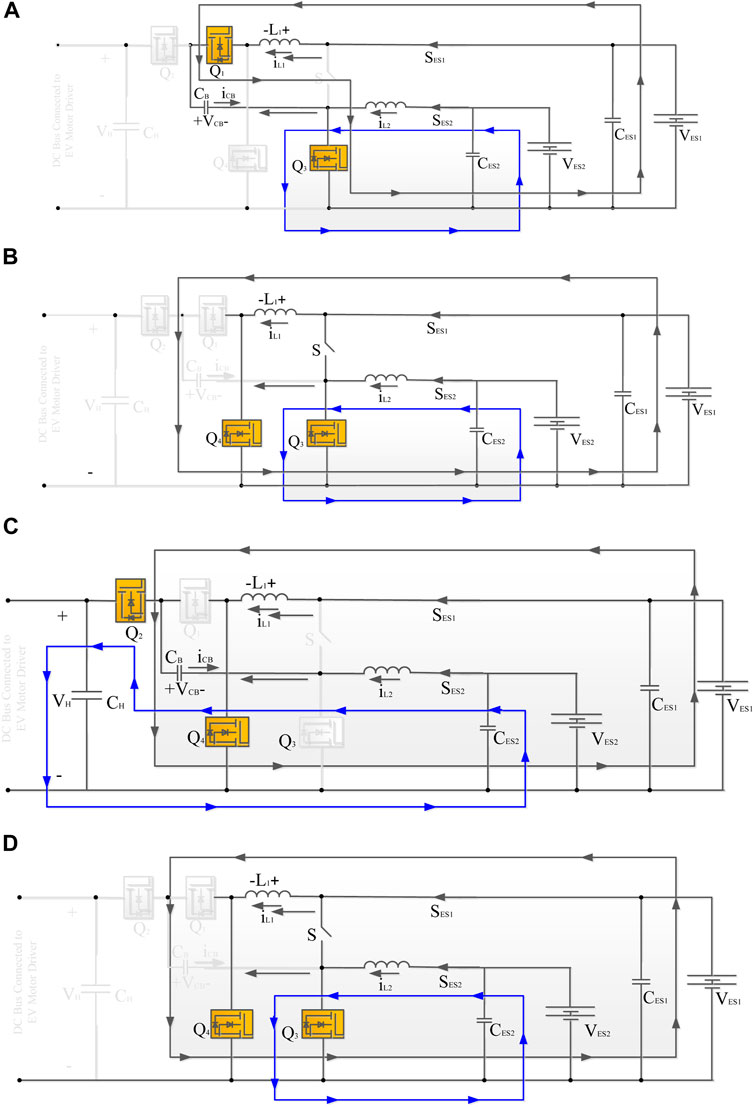
FIGURE 4. The proposed BDCC’s circuit states for the dual-source low-voltage powering levels. (A) Level 1(B) Level 2 (C) Level 3 (D) Level 4.
(1-Du)Tsw is the duration of the operation. The MOSFETsQ1, Q3, and Q2, Q4 are active throughout the period, whereas Q2, Q4 are dormant. The difference between VES1 and VCB is the voltage across L1. As a result, iL1 decreases linearly from its basic value, whereas L2 is charged by VES2in Figure 4A. Therefore, the inductor current rises linearly (Jang and Jovanovic, 2007). The relevant Eqs (Ehsani et al., 1997; Emadi et al., 2005)
The length of time is (Du-0.5). In this state Tsw, transistorsQ3 and Q4 are active, while Q1 and Q2 are inactive. Low-side voltages VES1 and VES2 are located between inductors L1 and L2, respectively, rising inductor currents linearly and initiating energy storage as indicated in Figure 4B. The voltages across inductors L1 and L2 may be expressed as Eq. (Emadi et al., 2006; Schaltz et al., 2009).
(1-Du)Tswis the duration. The transistorsQ1 and Q3 are active throughout this time, whereas Q2 and Q4 are idle, in Figure 4C. The voltage expressions are (Thounthong et al., 2009; Chan et al., 2010)
The duration is (Du-0.5)Tsw in this interval the transistorsQ3 and Q4 are active and Q1 and Q2 are inactive in Figure 4D. The voltages expressions can be written as Eqs (Khaligh and Li, 2010; Rajashekara, 2013)
Electricity is continuously supplied to and retrieved from the motor drive in this mode. There is a possibility that the regeneration power will exceed the battery’s ability to absorb it. A Rechargeable battery-powered storage device is an excellent option for this maximum electricity (Lai et al., 2018). Figure 5 (a) presents the BDCC circuit architecture and standard state pattern in the energy-regenerating high-voltage dc-link mode.
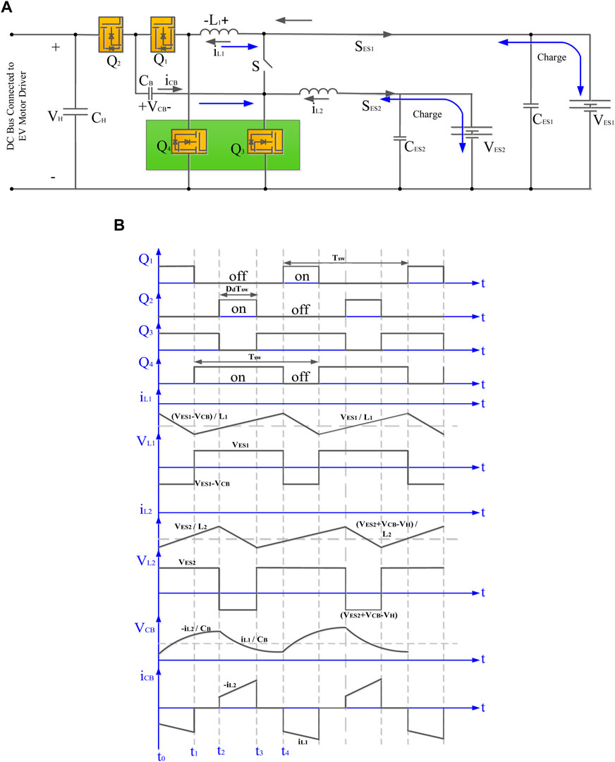
FIGURE 5. The proposed BDCC’s energy-regenerating high-voltage dc-link mode: (A) Circuit design (B) Stable pattern.
The inductive current may be adjusted with the 1800 phase angle using active switchesQ1, Q2. To increase the conversion efficiency illustrated in Figure 5, the remaining switchesQ3, and Q4 will operate as SR shown in Figure 5A, the stable waveforms duty ratio is less than 50%, as shown in Figure 5B, with these four various levels being achievable and stated as follows.
The period is DdTsw, and Q1 and Q3 are active, while Q2 and Q4 are inactive. The variation between the lowered voltage VES1 and the charge-pump voltage VCB is equal to the voltage across L1, therefore the inductor current iL1 steadily drops from its beginning value seen in Figure 6A. The energy source VES2 also charges inductor L2, causing the inductor current to expand linearly. The following are the important Eqa (Lai et al., 2015; Lai, 2016):
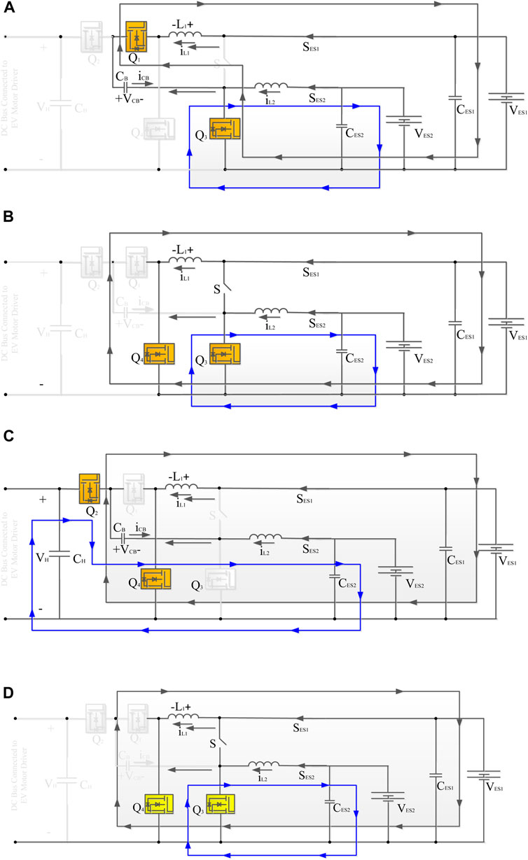
FIGURE 6. The proposed BDCC’s circuit states for the energy-regenerating high-voltage dc-link levels: (A) Level 1(B) Level 2 (C) Level 3 (D) Level 4.
The length of time is (0.5-Dd) The MOSFETsQ3 and Q4 are active in this scenario, whereas Q1 and Q2 are inactive. Inductor currents iL1 and iL2 develop linearly as L1 and L2 are positive in relation to the low-side voltages VES1 and VES2, as illustrated in Figure 6B are Eqs 11, 12.
The duration is DdTsw in this scenario, and the transistorsQ1 and Q3 are inactive, while Q2 and Q4 are active from Figure 6C. The application of a positive low-side voltage VES1 across L1 causes iL1 to expand linearly from its original value. Because of the discrepancy between the high-side voltage VH, the charge-pump voltage VCB, and the low-side voltage VES2, the voltage across L2 is also negative. The relevant Eqs [ 13–14] are as follows
2.2.3. Level 4 [t3< t < t4]: The period is (0.5-Dd)Tsw in this case, and the switchesQ3 and Q4 are active, while Q1 and Q2 are passive shown in Figure 6D are Eqs 15, 16
Figure 7 shows that the energy is exchanged from the primary store to the improved storage. In this phase, the converter is a single-leg bidirectional buck-boost.
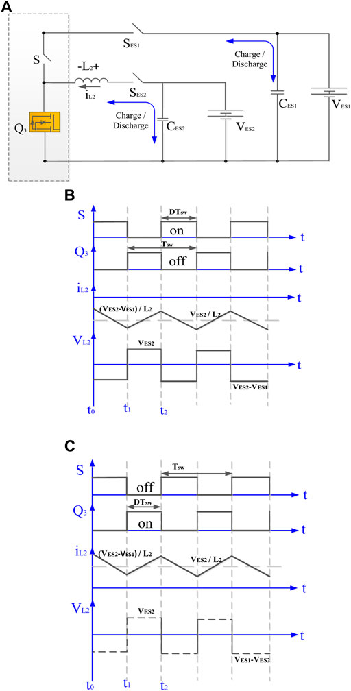
FIGURE 7. The proposed BDCC’s low voltage dual-source Buck/Boost mode: (A) Circuit architecture (B) Steady-State patterns in Buck mode (C) Boost mode steady-state patterns.
According to Figure 8, the active bidirectional switch S’s duty cycle can be altered, which triggers the buck converter to switch power over to secondary energy storage.
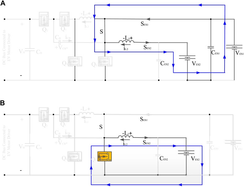
FIGURE 8. The proposed BDCC circuit states for the low voltage dual-source buck mode (A) level 1 and (B) level 2.
According to Figure 9, primary and supplementary energy storage are both boosted when the transistor’sQ3 duty cycle is adjusted to signal that it is in “boost operation mode.
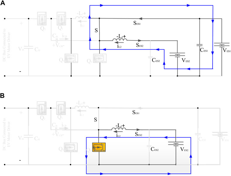
FIGURE 9. The suggested BDCC circuit states for the low voltage dual-source boost mode (A) level 1 and (B) level 2.
The BDC controller of the converter control system is depicted in Figure 10A, which contains a vehicular strategic management level. Figure 10B represents a real-time DSP flowchart used to test various working modes of the proposed BDCCs.
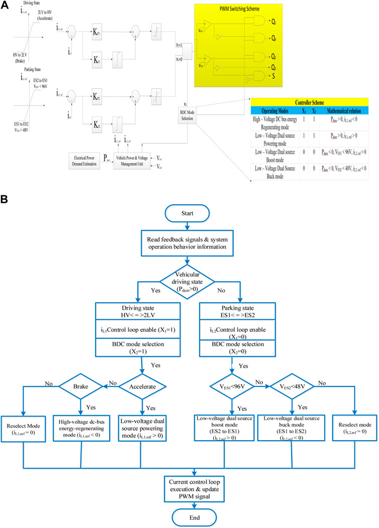
FIGURE 10. (A) Block diagram of the closed-loop control method; (B) designed DSP flowchart of the proposed BDCC’s multiple operating modes (Lai et al., 2018).
The regulation of flow in two ways from a lower potential source at two sides and a higher potential dc bus is shown in Figure 10A by using the current reference (iL1, ref). This BDCC topology’s uniform average current sharing means that iL2 is nearly identical to iL1 regulated average inductor current. In distinction, the reference at current iL2, ref is employed for regulating the flow of power from primary and secondary energy storage systems. By using the triangular wave as one of the inputs, such as vtri1 and vtri2, the PWM ON and OFF method turns the total time dictated by a distinct selection of switches for switching ON gate control of power switches. It then chooses one of two current references, iL1, ref or iL2, ref, to regulate the switches (S, Q1-Q4) using PI or more complex approaches.
Figure 10B depicts the switching mode strategy, which is further detailed in the following diagram. To begin, the controller is in the iL1 control loop (x1 = 1) while the vehicle is in driving mode (Pdem>0), and the switch button which can be controlled is mentioned in Table 2 (the vehicle is accelerating (iL1, ref>0, HV to 2 LV) or braking (iL1, ref 0, 2 LV to HV). If none of these circumstances applies, the following mode switching judgment will be processed using reselect mode. Furthermore, the controller is in the iL2 control loop (x1 = 0) while the automobile is in the parking state (Pdem<0), and the switches are controlled as shown in Table 2. In this situation, the voltages of VES1 (96 V) and VES2 (72 V) influence mode switching (48 V). The mode is a low-voltage dual-source boost (iL2, ref>0, VES2 to VES1) while VES1<96 V is present, and a low-voltage dual-source buck (iL2, ref>0, VES1 to VES2) when VES2<48 V is present. If none of these requirements is fulfilled, the following mode switching judgment is processed using reselect mode. Based on the state-space averaging approach, only regulators with two closed-loop are designed to regulate the power flow in four conditions.
From Figure 11: the notations are
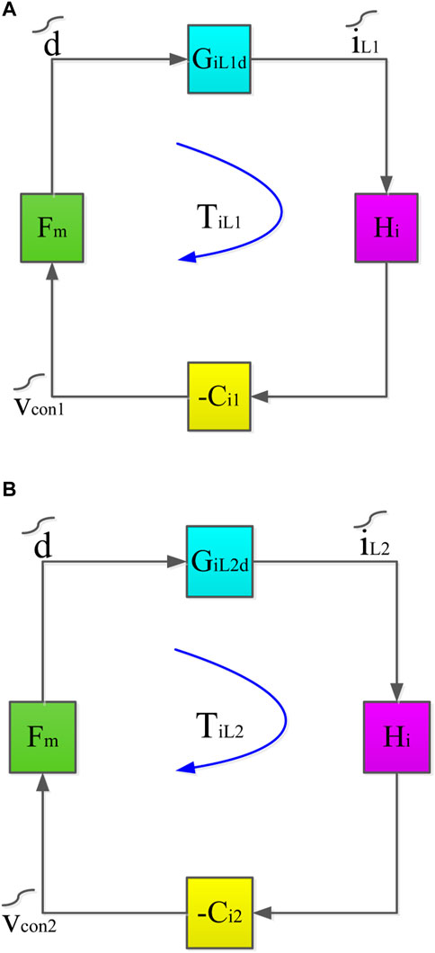
FIGURE 11. Diagrams demonstrating a closed-loop control method for (A) the energy from an energy-regenerating high-voltage dc-link mode and (B) the Dual-source low-voltage powering mode.
Fm: Indicates the PWM generator’s constant gain.
GiL1d: Represents the ON and OFF cycle to current at inductor iL1 conversion function.
GiL2d: ON and OFF cycle to current at inductor controller transfer function.
Hi: Gain of the current sensor.
Ci1 and Ci2: Depict the inductor current controllers’ transfer function
Figures 11A,B depict closed-loop control block designs for lower-potential sources at dual end buck or boost (LV to HV) and higher-potential dc-bus power-regeneration modes, respectively.
Simulations are performed to check the performance of the suggested model, with the parameter components of C = 10µF, L = 250 mH, and V = 48V, 96 V and DC motor is assumed as an electric vehicle.
The model simulation is done in MATLAB-Simulink. The results are presented and discussed below.
The system power transmission from the dc-bus to the main & auxiliary energy storage is depicted in Figure 12. Currents flow in the opposite direction as the input power in inductors iL1 and iL2. VES1 and VES2 were at 96 V and 48V, respectively, on the low end.
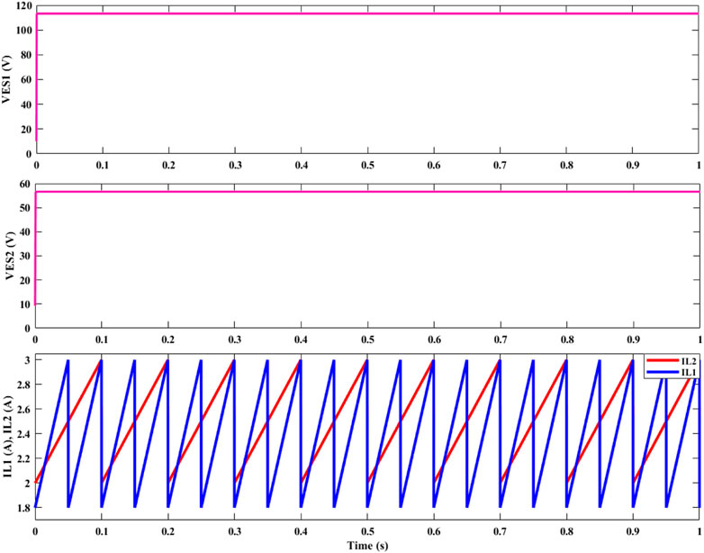
FIGURE 12. Output voltage and inductor currents for a higher-potential dc-bus power-regenerating mode were measured.
Figures 13A,B illustrate that currents in inductors are exactly the opposite of what we can see, indicating that the model works well for both primary and secondary energy storage.
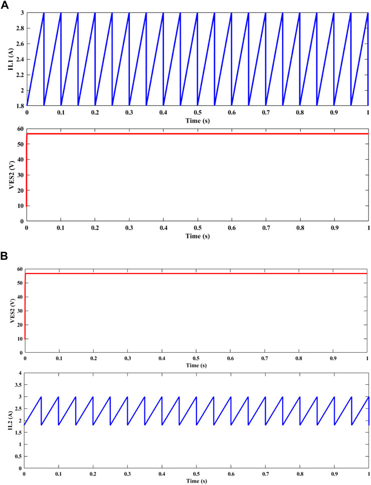
FIGURE 13. Low-voltage dual-source buck/boost mode, waveforms of output voltage, and inductor currents: (A) Boost Mode; (B) Buck Mode.
For the simulated system, these Figures 14, 15 depict the regulated current step shift waveforms in the lower potential dual-source providing and higher potential dc-bus electricity modes. The power flow was efficiently reversed, as indicated by the negative current waveforms, by changing iH and iL1 currents from low-side sources to supply 360 W of power to the elevated bus, as shown in Figures 14, 15.
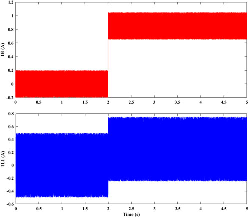
FIGURE 14. Simulation patterns of a managed current change in step in lower-potential dual-source powering mode (iH altered from 0 to 0.85 A; iL1 changed from 0 to 2.5 A).
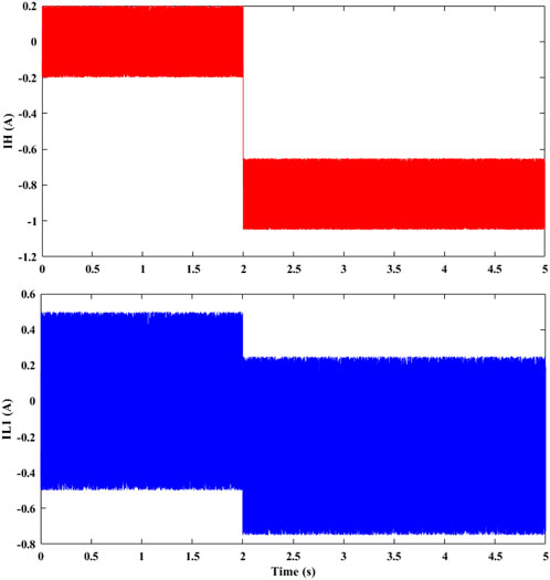
FIGURE 15. Simulation patterns of managed changes in current at step level in the higher-potential dc-bus power-regenerating mode (iH altered from 0 to −0.85 A; iL1 changed from 0 to −2.5 A).
We may adjust the current step shift of the prototype system using these two low-voltage operation modes, low voltage boost and low voltage buck. The raised current iES1 and the inductance current iL2 were both modified to supply 576 W of power between reduced dual sources, as depicted in Figure 16A. The negative current waveform in Figure 16B shows how the output current was effectively reversed.
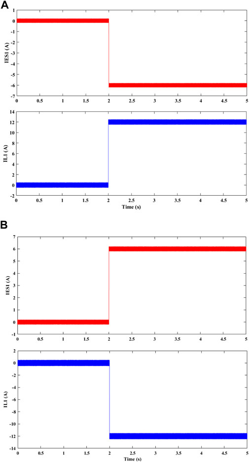
FIGURE 16. Simulation patterns of a managed step change in current in lower potential dual-source (A) Boosting Mode and (B) Buck Mode.
Comparisons of the proposed BDCC’s performance with existing models in the relevant literature are exhibited in Table 3.
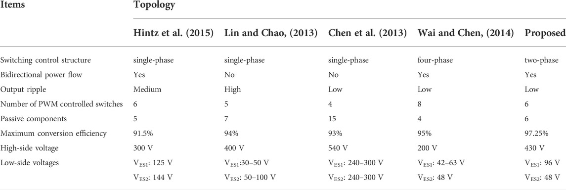
TABLE 3. Illustrating the difference in the performance among a wide range of converters.
Compared the proposed converter with the ones in (Lin and Chao, 2013) and (Chen et al., 2013), point out the fact that our converter includes fewer passive components. A further limitation of the other models is their inability to transfer energy in both directions. Although both (Hintz et al., 2015) and (Wai and Chen, 2014) claim to have bidirectional power flow, their best conversion efficiency is less than that of the converter suggested in this work. Furthermore, compared to the models provided in (Chen et al., 2013; Lin and Chao, 2013; Wai and Chen, 2014; Hintz et al., 2015), the proposed BDCC has a greater voltage conversion ratio.
This paper has explained the evolution of advanced bidirectional DC to DC converter topology. From BDCC, twin low voltage powering function, both the accelerating mode and braking mode were explained. In the case of high voltage powering function buck and boost, the model has been operated by controlling the switches. Also, a novel converter control for vehicle strategic management level, designed for the proposed BDCC controller with the help of digital signal processor (DSP) flow chart representations was presented. Various power transmission methods were used to handle the recommended BDC’s circuit layout, operating principles, analysis, and static voltage gains. A simulation system has been used to study and analyze the proposed BDCC topology’s performance and viability. It was found that the maximum energy capacity of the four different types of lower-potential dual-source charging systems is 97%, 95%, 95%, and 96%. The outputs have shown that suggested BDCC implements an electric hybrid design in FC/HEV systems. So, Electric vehicles (EVs) will increase battery availability. To put this in context, identifying applications for a lot of power generation potentials can provide tremendous value and even help drive down the cost of storage, allowing for more sustainable inclusion into our grids.
The original contributions presented in the study are included in the article/Supplementary Material, further inquiries can be directed to the corresponding authors.
KVGR and MKK: Conceptualization, Data curation, Formal analysis, Methodology, Resources, Software, Validation, Visualization, Writing—original draft. BSG: Data curation, Investigation, Supervision., KVGR, SK, and MB: Writing—review and editing. All authors have read and agreed to the published version of the manuscript.
The authors declare that the research was conducted in the absence of any commercial or financial relationships that could be construed as a potential conflict of interest.
All claims expressed in this article are solely those of the authors and do not necessarily represent those of their affiliated organizations, or those of the publisher, the editors and the reviewers. Any product that may be evaluated in this article, or claim that may be made by its manufacturer, is not guaranteed or endorsed by the publisher.
Azizi, I., and Radjeai, H. (2015). “A bidirectional DC-DC converter fed DC motor for electric vehicle application,” in 2015 4th International Conference on Electrical Engineering (ICEE), Boumerdes, Algeria, December 2015 (IEEE), 1–5. doi:10.1109/INTEE.2015.7416683
Bauman, J., and Kazerani, M. (2008). A comparative study of fuel-cell–battery, fuel-cell–ultracapacitor, and fuel-cell–battery–ultracapacitor vehicles. IEEE Trans. Veh. Technol. 57 (2), 760–769. doi:10.1109/tvt.2007.906379
Bhattacharya, T., Giri, V. S., Mathew, K., and Umanand, L. (2009). Multiphase bidirectional flyback converter topology for hybrid electric vehicles. IEEE Trans. Ind. Electron. 56 (1), 78–84. doi:10.1109/tie.2008.2004661
Chan, C. C., Bouscayrol, A., and Chen, K. (2010). Electric, hybrid, and fuel-cell vehicles: Architectures and modeling. IEEE Trans. Veh. Technol. 59 (2), 589–598. doi:10.1109/tvt.2009.2033605
Chauhan, A. K., Vakacharla, V. R., Verma, A. K., and Singh, S. K. (2016). “Multiple PMSG fed Non-inverting buck-boost converter for HEVs,” in 2016 IEEE 6th International Conference on Power Systems (ICPS), New Delhi, India, March 2016 (IEEE), 1–6. doi:10.1109/ICPES.2016.7584156
Chen, Y.-M., Huang, A. Q., and Yu, X. (2013). A high step-up three-port dc–dc converter for stand-alone PV/battery power systems. IEEE Trans. Power Electron. 28 (11), 5049–5062. doi:10.1109/tpel.2013.2242491
Ehsani, M., Gao, Y., and Emadi, A. (2009). Modern electric, hybrid electric, and fuel cell vehicles: Fundamentals, theory, and design. CRC Press.
Ehsani, M., Rahman, K. M., and Toliyat, H. A. (1997). Propulsion system design of electric and hybrid vehicles. IEEE Trans. Ind. Electron. 44 (1), 19–27. doi:10.1109/41.557495
Emadi, A., Rajashekara, K., Williamson, S. S., and Lukic, S. M. (2005). Topological overview of hybrid electric and fuel cell vehicular power system architectures and configurations. IEEE Trans. Veh. Technol. 54 (3), 763–770. doi:10.1109/tvt.2005.847445
Emadi, A., Williamson, S. S., and Khaligh, A. (2006). Power electronics intensive solutions for advanced electric, hybrid electric, and fuel cell vehicular power systems. IEEE Trans. Power Electron. 21 (3), 567–577. doi:10.1109/tpel.2006.872378
Farhangi, B., and Toliyat, H. A. (2015). Modeling and analyzing multiport isolation transformer capacitive components for onboard vehicular power conditioners. IEEE Trans. Ind. Electron. 62 (5), 3134–3142. doi:10.1109/tie.2014.2386800
Fong, Y. C., Wang, D. H., Mei, J., Raman, S. R., and Cheng, K. W. E. (2020). “Study and development of Mixed Repurposing EV battery system for Stationary energy storage applications,” in 2020 8th International Conference on Power Electronics Systems and Applications (PESA), Hong Kong, China, December 2020 (IEEE), 1–6. doi:10.1109/PESA50370.2020.9343967
Gao, Y., Wang, W., and Li, Y. (2019). “Optimization of control strategy for dual-motor Coupling propulsion system based on dynamic Programming method,” in 2019 3rd Conference on Vehicle Control and Intelligence (CVCI), Hefei, China, September 2019 (IEEE), 1–6. doi:10.1109/CVCI47823.2019.8951627
Georgious, R., Saeed, S., Garcia, J., and Garcia, P. (2020). “Switching Schemes of the bidirectional buck-boost converter for energy storage system,” in 2020 IEEE Vehicle Power and Propulsion Conference (VPPC), Gijon, Spain, December 2020 (IEEE), 1–5. doi:10.1109/VPPC49601.2020.9330869
Gummi, K., and Ferdowsi, M. (2010). Double-input dc–dc power electronic converters for electric-drive vehicles Topology exploration and synthesis using a single-pole triple-throw switch. IEEE Trans. Ind. Electron. 57 (2), 617–623. doi:10.1109/tie.2009.2032762
Haihua, Z., and Khambadkone, A. M. (2008). “Hybrid modulation for dual active bridge bi-directional converter with extended power range for ultracapacitor application,” in Industry Applications Society Annual Meeting, Edmonton, AB, Canada, October 2008 (IAS'08 IEEE), 1–8.
Herath, N., Binduhewa, P., Samaranayake, L., Ekanayake, J., and Longo, S. (2017). “Design of a dual energy storage power converter for a small electric vehicle,” in 2017 IEEE International Conference on Industrial and Information Systems (ICIIS), Peradeniya, Sri Lanka, December 2017 (IEEE), 1–6. doi:10.1109/ICIINFS.2017.8300393
Hintz, A., Prasanna, U. R., and Rajashekara, K. (2015). Novel modular multiple-input bidirectional DC–DC power converter (MIPC) for HEV/FCV application. IEEE Trans. Ind. Electron. 62 (5), 3163–3172. doi:10.1109/tie.2014.2371778
Jang, Y., and Jovanovic, M. M. (2007). Interleaved boost converter with intrinsic voltage-doubler characteristic for universal-line PFC front end. IEEE Trans. Power Electron. 22 (4), 1394–1401. doi:10.1109/tpel.2007.900502
Jiang, L., Mi, C. C., Li, S., Zhang, M., Zhang, X., and Yin, C. (2013). A novel soft-switching bidirectional DC–DC converter with coupled inductors. IEEE Trans. Ind. Appl. 49 (6), 2730–2740. doi:10.1109/tia.2013.2265874
Jung, D.-Y., Hwang, S.-H., Ji, Y.-H., Lee, J.-H., Jung, Y.-C., and Won, C.-Y. (2013). Soft-switching bidirectional DC/DC converter with a LC series resonant circuit. IEEE Trans. Power Electron. 28 (4), 1680–1690. doi:10.1109/tpel.2012.2208765
Khaligh, A., and Li, Z. (2010). Battery, ultracapacitor, fuel cell, and hybrid energystorage systems for electric, hybrid electric, fuel cell, and plug-in hybrid electric vehicles: State of the art. IEEE Trans. Veh. Technol. 59 (6), 2806–2814. doi:10.1109/tvt.2010.2047877
Kharade, J. M., Patil, A. A., Yadav, N. V., Kamble, B. D., and Virbhadre, A. B. (2021). “Dual battery charger system for electric vehicle,” in 2021 Second International Conference on Electronics and Sustainable Communication Systems (ICESC), Coimbatore, India, August 2021 (IEEE), 157–161. doi:10.1109/ICESC51422.2021.9532862
Krishnaswami, H., and Mohan, N. (2009). Three-port series-resonant DC–DC converter to interface renewable energy sources with bidirectional load and energy storage ports. IEEE Trans. Power Electron. 24 (10), 2289–2297. doi:10.1109/tpel.2009.2022756
Lai, C.-M. (2016). Development of a novel bidirectional DC/DC converter topology with high voltage conversion ratio for electric vehicles and DC-microgrids. Energies 9 (6), 410. doi:10.3390/en9060410
Lai, C.-M., Lin, Y.-C., and Lee, D. (2015). Study and implementation of a two-phase interleaved bidirectional DC/DC converter for vehicle and dc-microgrid systems. Energies 8 (9), 9969–9991. doi:10.3390/en8099969
Lai, C., Cheng, Y., Hsieh, M., and Lin, Y. (2018). Development of a bidirectional DC/DC converter with dual-battery energy storage for hybrid electric vehicle system. IEEE Trans. Veh. Technol. 67 (2), 1036–1052. doi:10.1109/TVT.2017.2763157
Lin, B.-R., and Chao, C.-H. (2013). Soft-switching converter with two series half-bridge legs to reduce voltage stress of active switches. IEEE Trans. Ind. Electron. 60 (6), 2214–2224. doi:10.1109/tie.2012.2191758
Liu, Y.-C., and Chen, Y.-M. (2009). A systematic approach to synthesizing multi-input DC–DC converters. IEEE Trans. Power Electron. 24 (1), 116–127. doi:10.1109/tpel.2008.2009170
Lu, Y., Liu, S., Wu, M., and Kong, D. (2021). “Energy management of dual energy sources pure electric vehicle based on Fuzzy control,” in 2021 IEEE International Conference on Internet of Things and Intelligence Systems (IoTaIS), Bandung, Indonesia, November 2021 (IEEE), 228–233. doi:10.1109/IoTaIS53735.2021.9628658
Manjunatha, K. C., and Manjesh, (2017). “Design and development of fly-back converter with buck-boost regulator for DC motor used in electric vehicle for the application of renewable energy,” in 2017 International Conference on Circuit ,Power and Computing Technologies (ICCPCT), Kollam, India, April 2017 (IEEE), 1–4. doi:10.1109/ICCPCT.2017.8074256
Mehta, C. P., and Balamurugan, P. (2016). “Buck-Boost converter as power factor correction controller for plug-in electric vehicles and battery charging application,” in 2016 IEEE 6th International Conference on Power Systems (ICPS), New Delhi, India, March 2016 (IEEE), 1–6. doi:10.1109/ICPES.2016.7584111
Monteiro, V., Ferreira, J. C., Nogueiras Meléndez, A. A., Couto, C., and Afonso, J. L. (2018). Experimental Validation of a novel architecture based on a dual-Stage converter for off-Board Fast battery Chargers of electric vehicles. IEEE Trans. Veh. Technol. 67 (2), 1000–1011. doi:10.1109/TVT.2017.2755545
Moradisizkoohi, C. H., Elsayad, N., and Mohammed, O. A. (2019). Experimental Verification of a double-input soft-Switched DC–DC converter for fuel cell electric vehicle with hybrid energy storage system. IEEE Trans. Ind. Appl. 55 (6), 6451–6465. doi:10.1109/TIA.2019.2937288
Moreno, J., Ortúzar, M. E., and Dixon, J. W. (2006). Energy-management system for a hybrid electric vehicle, using ultracapacitors and neural networks. IEEE Trans. Ind. Electron. 53 (2), 614–623. doi:10.1109/tie.2006.870880
Nayak, P. S. R., Kamalapathi, K., Laxman, N., and Tyagi, V. K. (2021). “Design and simulation of BUCK-BOOST type dual input DC-DC converter for battery charging application in electric vehicle,” in 2021 International Conference on Sustainable Energy and Future Electric Transportation (SEFET), Hyderabad, India, January 2021 (IEEE), 1–6. doi:10.1109/SeFet48154.2021.9375658
Nguyen, H. V., To, D. -D., and Lee, D. -C. (2018). Onboard battery Chargers for plug-in electric vehicles with dual functional circuit for low-voltage battery charging and active power Decoupling. IEEE Access 6, 70212–70222. doi:10.1109/ACCESS.2018.2876645
Omara, A. M., and Sleptsov, M. (2016). “Bidirectional interleaved DC/DC converter for electric vehicle application,” in 2016 11th International Forum on Strategic Technology (IFOST), Novosibirsk, Russia, June 2016 (IEEE), 100–104. doi:10.1109/IFOST.2016.7884201
Prajapati, Y., and Maurya, R. (2019). “Battery charging station for multiple electric vehicles with power conditioning,” in 2019 IEEE 1st International Conference on Energy, Systems and Information Processing (ICESIP), Chennai, India, July 2019 (IEEE), 1–6. doi:10.1109/ICESIP46348.2019.8938243
Rahimifard, S., Habibi, S., and Tjong, J. (2020). “Dual Estimation strategy for new and aged electric vehicles batteries,” in 2020 IEEE Transportation Electrification Conference & Expo (ITEC), Chicago, IL, USA, June 2020 (IEEE), 579–583. doi:10.1109/ITEC48692.2020.9161556
Rahman, M. M., Uddin, M. N., and Islam, M. K. (2015). “Performance enhancement of a bi-directional DC-DC converter using a Ćuk converter for electric vehicle applications,” in 2015 IEEE 28th Canadian Conference on Electrical and Computer Engineering (CCECE), Halifax, NS, Canada, May 2015 (IEEE), 875–880. doi:10.1109/CCECE.2015.7129390
Rajashekara, K. (2013). Present status and future trends in electric vehicle propulsion technologies. IEEE J. Emerg. Sel. Top. Power Electron. 1 (1), 3–10. doi:10.1109/jestpe.2013.2259614
Ruan, J., and Song, Q. (2019). A novel dual-motor two-speed Direct drive battery electric vehicle Drivetrain. IEEE Access 7, 54330–54342. doi:10.1109/ACCESS.2019.2912994
Sakr, N., Sadarnac, D., and Gascher, A. (2015). “A new combined bidirectional boost converter and battery charger for electric vehicles,” in IECON 2015 - 41st Annual Conference of the IEEE Industrial Electronics Society, Yokohama, Japan, November 2015 (IEEE), 001258–001263. doi:10.1109/IECON.2015.7392273
Schaltz, E., Khaligh, A., and Rasmussen, P. O. (2009). Influence of battery/ultracapacitor energy-storage sizing on battery lifetime in a fuel cell hybrid electric vehicle. IEEE Trans. Veh. Technol. 58 (8), 3882–3891. doi:10.1109/tvt.2009.2027909
Tao, H., Duarte, J. L., and Hendrix, M. A. (2008). Three-port triple-half-bridge bidirectional converter with zero-voltage switching. IEEE Trans. Power Electron. 23 (2), 782–792. doi:10.1109/tpel.2007.915023
Thounthong, P., Chunkag, V., Sethakul, P., Davat, B., and Hinaje, M. (2009). Comparative study of fuel-cell vehicle hybridization with battery or supercapacitor storage device. IEEE Trans. Veh. Technol. 58 (8), 3892–3904. doi:10.1109/tvt.2009.2028571
Trovão, J. P. F., Roux, M., Ménard, É., and Dubois, M. R. (2017). Energy- and power-Split management of dual energy storage system for a three-Wheel electric vehicle. IEEE Trans. Veh. Technol. 66 (7), 5540–5550. doi:10.1109/TVT.2016.2636282
Wai, R.-J., and Chen, B.-H. (2014). High-efficiency dual-input interleaved DC–DC converter for reversible power sources. IEEE Trans. Power Electron. 29 (6), 2903–2921. doi:10.1109/tpel.2013.2275663
Wang, W., Zhang, Z., Shi, J., Lin, C., and Gao, Y. (2018). Optimization of a dual-motor coupled Powertrain energy management strategy for a battery electric bus based on dynamic Programming method. IEEE Access 6, 32899–32909. doi:10.1109/ACCESS.2018.2847323
Wu, H., Sun, K., Ding, S., and Xing, Y. (2013). Topology derivation of non-isolated three-port DC–DC converters from DIC and DOC. IEEE Trans. Power Electron. 28 (7), 3297–3307. doi:10.1109/tpel.2012.2221746
Zhao, B., Song, Q., and Liu, W. (2012). Power characterization of isolated bidirectional dual-active-bridge DC–DC converter with dual-phase-shift control. IEEE Trans. Power Electron. 27 (9), 4172–4176. doi:10.1109/tpel.2012.2189586
EV Electric Vehicle
BDCC Bidirectional DC/DC Converter
HEV Hybrid Electric Vehicle
DSP Digital Signal Processor
FCV Fuel Cell Vehicle
PHEV Plugin Hybrid electric vehicle
ESS Energy Storage System
SC Super Capacitor
MIMO Multi Input Multi Output
PI Proportional Integral
IGBT Integrated Bipolar Transistor
MOSFET Metal Oxide Semiconductor Field Effect Transistor
CCM Continuous Conduction Mode
PMSG Permanent Magnet Synchronous Generator
DP Dynamic Programming
OBC Onboard Battery Charger
LV Low Voltage
HV High Voltage
DAB Dual Active Bridge
BMS Battery Management System
SOH Stage of Health
DIBBC Dual Input Buck Boost Converter
SOC State of Charge
CB Charge Pump Capacitor
SR Synchronous Rectifier
PWM Pulse Width Modulator
ES1 Primary Battery
ES2 Auxiliary/Extra Battery
VH Higher Voltage Bus/DC Bus Voltage
IH High side current
iL1 & iL2 Inductor Currents
CL1 & CL2 Capacitor Currents
VES1, VES2 Energy Storage systems
S, SES1, SES2 Bidirectional Power Switches
CB Charge Pump Capacitor
Dd Duty Cycle of Q1 & Q2
Du Duty Cycle of Q3 & Q4
VCB Charge Pump Capacitor Voltage
Pdem Power Demand
Q1, Q2, Q3, Q4 Switches
L1, L2 Inductors
VES1, VES2 Voltage Sources
Keywords: bidirectional dc/dc converter (BDCC), bidirectional power flow, DSP flow chart, dual battery storage, hybrid electric vehicle
Citation: Venkata Govardhan Rao K, Kumar MK, Goud BS, Bajaj M, Abou Houran M and Kamel S (2022) Design of a bidirectional DC/DC converter for a hybrid electric drive system with dual-battery storing energy. Front. Energy Res. 10:972089. doi: 10.3389/fenrg.2022.972089
Received: 17 June 2022; Accepted: 25 October 2022;
Published: 09 November 2022.
Edited by:
Yimin Zhou, Shenzhen Institutes of Advanced Technology (CAS), ChinaReviewed by:
Mohamed Salem, Universiti Sains Malaysia (USM), MalaysiaCopyright © 2022 Venkata Govardhan Rao, Kumar, Goud, Bajaj, Abou Houran and Kamel. This is an open-access article distributed under the terms of the Creative Commons Attribution License (CC BY). The use, distribution or reproduction in other forums is permitted, provided the original author(s) and the copyright owner(s) are credited and that the original publication in this journal is cited, in accordance with accepted academic practice. No use, distribution or reproduction is permitted which does not comply with these terms.
*Correspondence: Malligunta Kiran Kumar, a2lyYW4ubWFsbGlndW50YUBnbWFpbC5jb20=; Salah Kamel, c2thbWVsQGFzd3UuZWR1LmVn
Disclaimer: All claims expressed in this article are solely those of the authors and do not necessarily represent those of their affiliated organizations, or those of the publisher, the editors and the reviewers. Any product that may be evaluated in this article or claim that may be made by its manufacturer is not guaranteed or endorsed by the publisher.
Research integrity at Frontiers
Learn more about the work of our research integrity team to safeguard the quality of each article we publish.