Abstract
This work investigates the application of sliding mode control (SMC) on a doubly fed induction generator (DFIG). In conventional control schemes like PI controllers, the responses are relatively slow, and the transient state is often subjected to sustained oscillation. Further, the PI control achieves lesser invariance behavior against system uncertainties, and the selection of its gain parameters is a skillful task. In contrast, the SMC is well-known for its faster convergence, robustness, and better transient and steady-state behavior. In this study, the nonsingular fast terminal sliding mode control (NSFTSMC) is applied in the speed loop of the rotor side vector control of DFIG. The proposed NSFTSMC scheme results in less speed fluctuation with a change in wind speed, which is maintained by controlling the torque component of the current (). This paper also presents detailed modeling of the DFIG, power converters, and the related control schemes. Moreover, stability analysis of the proposed methodology ensures the practical finite time stability of the overall system. The comparative controller performance and validation are carried out in Matlab/Simulink environment. The proposed control strategy presents much better results than conventional PI-based control.
1 Introduction
Deregulation of energy has led to less investment in larger conventional power plants and more investment into alternative non-conventional electrical power sources. Moreover, increase in the environmental pollution is of great concern (Necoechea-Porras et al., 2021). To solve these problems, two major technologies are playing pivotal role. One is to switch the electricity production from conventional fossil fuel-based sources to renewable energy-based sources. And the other is the use of efficient power electronic conversion in generation, distribution, and end-user applications (Abu-Rub et al., 2014). These distributed energy resources are finding place in microgrids which is the future of the power systems (Ahmad et al., 2019). presents a comprehensive market model to incorporate the renewable energy sources-based microgrids into Indian electricity market. A review is presented (Asaad et al., 2021), where the details of the wind energy generation in Indian perspective is discussed.
Out of all renewable energy resources, wind energy extraction is the fastest growing technology, and it is most viable option to complement other types of pollution-free generating systems (Bou-Rabee et al., 2020). Regular progress in wind-energy conversion systems was seen since 1970s, and the rapid development started in 1990s. The wind turbine-generator concepts and control strategies were developed, and various kinds of wind generators were built since then. Powerful control structures were developed to overcome the wind and grid side intermittencies (Slootweg et al., 2003; Li and Chen, 2008; Boukhezzar and Siguerdidjane, 2011). The control schemes have changed from conventional PI to nonlinear control, as it is much nearer in accuracy with the actual system (Elkington and Ghandhari, 2009; Hu et al., 2010). Implementation of these modern control schemes has become viable due to the developments in the microprocessor and semiconductor technology (Abu-Rub et al., 2014). Out of the wind turbine generator system configurations doubly fed induction generator (DFIG) comprises of approximately 55% of the total systems (Li and Chen, 2008; Abu-Rub et al., 2014). The main reasons being the variable speed range of ±30% of synchronous speed and that the converter ratings are of slip power rating. This leads to high energy yield and lower component stress (Boukhezzar and Siguerdidjane, 2011).
Field oriented control (FOC) and other (Ayedin et al., 2016) vector control techniques are employed to control the DFIG power electronics. FOC is commonly used in DFIGs due to its ability to control the machine speed more efficiently (Krishnan, 2001). Stator flux-oriented-FOC was first employed in (Pena et al., 1996). It was later used extensively (Tapia et al., 2003; Qiao et al., 2008), where the current component (q-axis) controls the active power, and the d-axis is employed to control the reactive power. While, in the stator voltage oriented-FOC, a contrary structure is used (Subudhi and Ogeti, 2018). Proportional-Integral (PI) controllers are commonly used in these schemes.
On the other hand, the sliding mode control (SMC) is a variable structure control technique in which an unstable system varies between the two structures using SMC to make the overall performance of the system stable (Utkin, et al., 2017). In addition, the switching between the two structures equips the controller with invariance property against model uncertainties and disturbances. Besides, the SMC method is easy to construct, achieves faster convergence, smooth response, better steady-state behavior, and easy to guarantee the finite-time stability of the system in theory (Chojaa, et al., 2021;
Amrr, et al., 2022). However, in practical scenario, achieving a finite time result with absolute zero error convergence is unrealistic. Therefore, recently, new results of practical finite time stability are proposed (Zhu, et al., 2011; Amrr, et al., 2020; Fu et al., 2021). Here, the closed loop signals converge to a small residual bound in the neighborhood of zero within finite time. In view of this result, the proposed work presents a nonsingular fast terminal sliding mode control (NSFTSMC) approach (Yang and Yang, 2011) for tracking the angular speed in the speed loop of the rotor side vector control of DFIG. The system is also subjected to the external load disturbances, which may cause fluctuations in the performance. In this work, the nonsingular fast terminal sliding mode control (NSFTSMC) is applied in the speed loop of the rotor side vector control of DFIG. The proposed NSFTSMC scheme results in less speed fluctuation with a change in wind speed, which is maintained by controlling the torque component of the current ().
The rest of the paper is organized as follows. In Section 2, a brief discussion on the machine model, aerodynamic model and the drive-train model is done. Section 3 presents vector control of grid side converter control with the basic PI concept taken. Then, FOC is implemented to the machine side converter control scheme with conventional PI controllers. The speed loop is dealt with simple PI controller in this case. In Section 4, the proposed NSFTSMC is designed for the speed loop and the stability analysis of the closed loop system is presented. Section 5 illustrates the comparative results and Section 6 concludes the paper.
2 Aerodynamics and machine model
The overall arrangement of a DFIG-based wind turbine generator (DFIG-WTGS) is shown in Figure 1A. The generator is connected to the wind turbine through a drive train system consisting of low-speed shaft, high speed shaft and the gear box system. A wound rotor induction generator is employed whose rotor either feeds the grid or takes the power into the machine thereby making the super-synchronous as well as the sub synchronous generation possible as shown in Figures 1B,C, respectively. The power entering the machine is the slip power and as a result the power capacity of the converters is of slip power rating. A back-to-back converter is employed to control the power entering the machine or leaving it. Moreover, active and reactive power flow from the stator of the machine can be controlled through the rotor side converter and the power flow in the rotor side is controlled by grid-side converter. This is achieved by keeping the DC-link voltage constant. In this manner DFIG-WTGS is isolated from the grid and making them both fluctuation-recumbent to each other.
FIGURE 1

(A) DFIG-WTGS Configuration Connected to Grid; power flow diagram of a DFIG in (B) Super-Synchronous and (C) Sub-Synchronous modes; and (D) curves for different Pitch angles; (E) Two–mass equivalent of three-bladed horizontal axis wind turbine generator system; (F) torque vs speed characteristics of a 1.5 MVA machine.
In all, three controls are needed to be developed to control the power being fed to the grid. The RSC and GSC employ electrical control schemes where PWM signals are provided to both the converters and the switching angles of the IGBTs may be changed with the fluctuation in the DC-link voltage. The third control scheme is required to control the pitch of the rotor blades which operates when the speed of the wind exceeds the rated speed.
2.1 Aerodynamic model
The aerodynamics of the wind-turbine can be shown by well-known curves known a power coefficient curves or, curves-as can be seen in Figure 1D. These can be achieved for different pitch angle (β) values by using the formulae given by (Neto et al., 2007) in as follows:where, is the tip speed ratio and can be defined as:where, R is the radius of the wind turbine in meters, is the rotational speed of the wind turbine in rad/sec and is the velocity of the wind in m/sec. The maximum mechanical power that can be extracted from the wind, which is given by (Ontiveros et al., 2010):where, is the density of the air in kg/m3.
2.2 Drive train model
A three-bladed horizontal axis wind turbine consists of six masses which can be lumped together to form a two-mass equivalent system, as shown in Figure 1E. It can be employed with reasonable accuracy for transient analysis (Boukhezzar and Siguerdidjane, 2011).
The equations for the two-mass model is given as (Muyeen et al., 2007):where,where, , are the angular position of the wind turbine and equivalent angular position of generator-gearbox system respectively. , are the angular velocity of the wind turbine and equivalent generator-gearbox system angular velocity, respectively. and are self-damping torques of the generator and gearbox respectively. and are generator and gearbox inertias respectively. and represent the elasticity between hub and gearbox, and gearbox and generator respectively. , and are the inertia, damping coefficient and the aerodynamic torque acting on a wind turbine. These quantities include the three blades and the hub. is the gear ratio. is hub and the gearbox mutual damping. Custom wind turbine aerodynamic and the drive train models are taken for the purpose of simulation of the systems.
2.3 Induction generator model
The DFIG voltage equations can be written in abc domain as:
The above equations are transformed into synchronously rotating reference frame to achieve dc values (Anaya-Lara et al., 2009; Krause et al., 2013):where, is the synchronous reference frame’s rotational speed and is the speed of the rotor. The flux linkages are given by:where, are the rotor-side leakage, stator-side leakage, and mutual inductance, respectively.
The electromagnetic torque developed can be given as:and the power expression of the stator and rotor side are given as:
The capital letters subscript are used for the stator side and the lower letter subscript for the rotor side. Also, the ‘’ and ‘’ subscripts are used for stator and rotor respectively in power equations. The free acceleration torque vs speed characteristics for 1.5 MVA machine, data of which has been taken from (Miller et al., 2003) to implement in MATLAB®/Simulink environment are shown in Figure 1 (f).
2.4 Voltage source converter model
The basic configuration of voltage source converter is shown as in Figure 2A. In the abc domain the equations are written as:where,
FIGURE 2
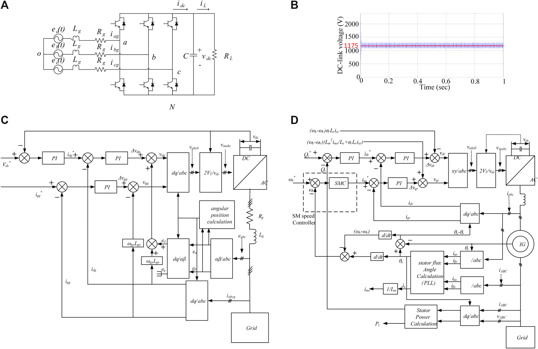
(A) voltage source converter configuration; (B) DC-link voltage behavior; (C) the grid side control scheme; (D) the rotor side control scheme with SMC implementation in the speed control loop.
and if a balanced three phase system is considered, then
and.
By applying PWM switching conditions and converting the equations onto the reference frame of the source voltage vector we can have following equations:where, and are the pulse width modulated switching functions that are expressed in d-q reference frame. The result of the model shown in Figure 2A when simulated with input rms (line to line) voltage as 380 V, the DC-link capacitor as 5 mF, 100 Ω load resistance, 0.46 modulation index (), and the carrier frequency of 1080 Hz, is shown in Figure 2B. The DC-link average voltage is around 1175 V, which is nearly double the input line to line voltage’s maximum value, and hence the three phase PWM converter is considered a boost converter whose value is given as:
3 Conventional control scheme
On the machine side, the DFIG requires two control schemes under consideration, the grid side control (GSC) and the rotor side control (RSC). The objective of the GSC is to maintain the zero DC-link voltage irrespective of the direction and magnitude of the rotor power. Reactive power regulation is done through GSC; while the main objective of the RSC is to regulate both the active power and the reactive power on the stator side independently. Another controller that is used is the pitch angle controller which is employed to control the mechanical power available at the shaft of the wind turbine when the speed of the wind is above the rated value.
3.1 GSC controller design
Two control loops work simultaneously. and -which are the gird side currents in synchronously rotating reference frame, are regulated independently through inner loops; while the outer loop regulates the DC-link voltage and the reactive power exchange.
Eq. 28 can be rearranged as:
Transforming the above equation into synchronously rotating reference frame, and aligning the d-axis along the grid voltage vector , we get the following equations:
Now aligning along the grid voltage vector gives us the advantage that and .
Now letand
Eqs. 39–40 can be rearranged as
This indicates that respond to , and respond to through a first order transfer function with no cross-coupling. This allows the design of the following feedback loop and PI control.
Substituting these values in Eqs 37, 38 we achieve following equations:
The power-balance equation across the DC-link is written as:
Above Equation can also be written as:where, and are the dc component of the DC-link voltage and the ripple content of the DC-link voltage respectively.
Since , Eq. 46 can be written as:
Therefore, the relation between and is given by:
Since,
Eq. 49 becomes
Therefore, the feedback loop and the PI controller generates a reference value of is designed as follows:
The reactive power exchanged through the GSC can be determined as follows
So, the reactive power may be regulated by regulating .
The overall control scheme can be seen in Figure 2C.
3.2 RSC controller design
Like GSC, RSC consists of cascaded control loops. The inner current control loop regulates the -axis and -axis rotor currents independently in accordance with the stator-flux oriented reference frame theory. This reference frame reduces the DFIG model to a second order system, as will be seen later. The outer control loop regulates the stator active power (that is the generator rotor speed) and the reactive power, independently.
In the stator-flux oriented reference frame theory, the -axis (here -axis) is associated with the stator flux linkage , which gives
Following results are achieved when applied to Eqs. 14–22where,
The stator power equations may be represented as
Eqs. 63–64 indicate that the stator active and reactive powers can be regulated independently by controlling and respectively. and can be determined through outer loops.
Firstly, the inner control loops; after proceeding as in the GSC control design, Eqs. 60, 61 may be written as:Where, and are used by the PWM module to generate the IGBT control signals.
4 Proposed nonsingular fast terminal sliding mode control
This section presents the rotor side vector control of DFIG using nonsingular fast terminal sliding mode control (NSFTSMC). Before going into the control design part, the dynamic model of vector drive of DFIG is given (Bose, 2002). Therefore, let us consider where is the desired angular position and is the angular position of wind turbine. Now, taking the time derivative of yields
Further, the second order mechanical dynamic equation of DFIG can be written in Laplace domain as (Zadehbagheri, et al., 2013)where is the disturbance load torque and is the electromechanical control torque, which is expressed aswhere and are the gain constants and is the control input, which is to be designed. Substituting (71) in (70) and converting it into time domain as
Eqs. 69 and 72 are the state space equations that can be rewritten in a simplified form aswhere , , . The following assumption and lemma are used for the stability proof.
Assumption 1The load disturbance is bound such that .
Lemma 1(Fu et al., 2021) considers a continuous system with being the equilibrium point and is the initial time. Suppose a positive definite Lyapunov function holds the inequality (75) for , , , and then, the solution of system is practically finite time stable. The settling time and residual bound of is given bywhere.
4.1 Controller design and stability analysis
The proposed control scheme is based on nonsingular fast terminal sliding surface (NSFTSS). The structure of the surface is inspired from (Tiwari, et al., 2012; Amrr and Nabi, 2020) and defined aswhere , and are positive coefficients of NSFTSS , and and . The time derivative of yields
In view of the derivative of from (80), the nonsingular fast terminal SMC (NSFTSMC) algorithm is defined aswhere is the nominal component and is the discontinuous component, and they are expressed asandwhere , , and .
Considering the sliding dynamics (80) and the proposed NSFTSMC law (75) under Assumption 1. The action of the proposed methodology will achieve the practical finite time stability and the sliding surface will converge to a small residual bound of zero. Moreover, the relative states and will also converge to the vicinity of origin in the sense of practical finite time stability.
Proof. Consider a Lyapunov function.
The time derivative of gives
Substituting the proposed control law from 82–86 yieldswhere , which is a lumped value. Now, using completing the square technique (Amrr and Nabi, 2019) by introducing a constant such that . Further, adding and subtracting a term in (89) aswhere , , , , . Considering Lemma 1, Eq. 91 satisfies the practical finite time stability condition. Therefore, sliding surface will converge to the narrow bound of zero as defined in Eq. 76 and the settling time as (77). Moreover, the relative states and will also converge to the uniformly ultimate bound within finite time (i.e., practical finite time stable). This convergence proof is not presented here due to brevity and word limitation. However, the similar proof can be seen from (Amrr and Alturki, 2021).
5 Results
The DFIG with the above-discussed NSFTSMC scheme is implemented on the RSC of the DFIG as shown in Figure 2D. The system is connected to the grid and validated in MATLAB/Simulink environment as shown in Figure 3A. The DFIG ratings are taken from the technical report by (Miller et.al., 2003). The wind is emulated in the Simulink environment by using a signal builder block as a sampled Gaussian noise, as discussed by in (Patel and Beik, 2021). Figure 3B shows random behavior of wind. The rated wind speed is 15 m/s.
FIGURE 3
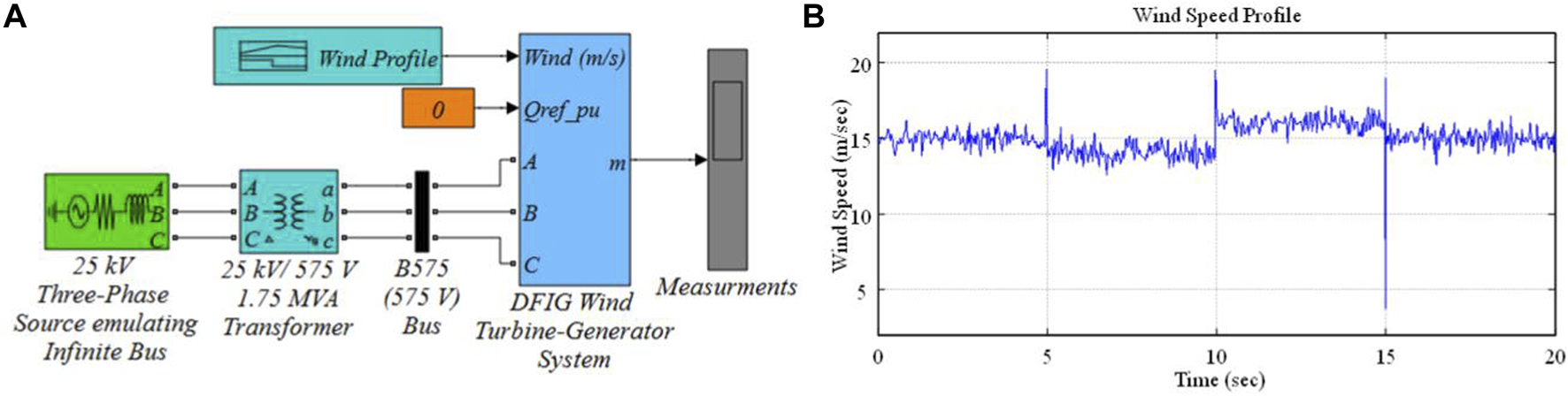
(A) The system configuration under study; (B) wind speed variation subjected to the wind turbine blades.
Conventional PI speed controller and NSFTSMC schemes were implemented, and the performance was compared. The analysis is as follows. The rotor shaft’s base speed is 1.2 times the synchronous speed of the machine. The actual rotor shaft speed behavior with both PI and NSFTSMC is shown in Figure 4A. It can be observed that the speed of the rotor is more stable with the NSFTSMC as compared with conventional PI Control, when the turbine is subjected to a wind speed change. It is also observed that the rotor speed settles much faster with NSFTSMC than the PI controller. The DC-link voltage remains unaltered with both the control schemes as seen in Figure 4B. The pitch angle variation (Figure 4C), however, is more stable in the case of conventional PI than the NSFTSMC. The grid side voltage performance is shown in Figure 4D and exhibits similar behavior with both control schemes. Figure 4E exhibits the output current of phase A, and it is seen that there are disturbances with the NSFTSMC, and this disturbance is also observed in active power (Figure 4F) and electromagnetic torque (Figure 4H). The reactive power behavior of the machine is similar for both machines as exhibited Figure 4G.
FIGURE 4
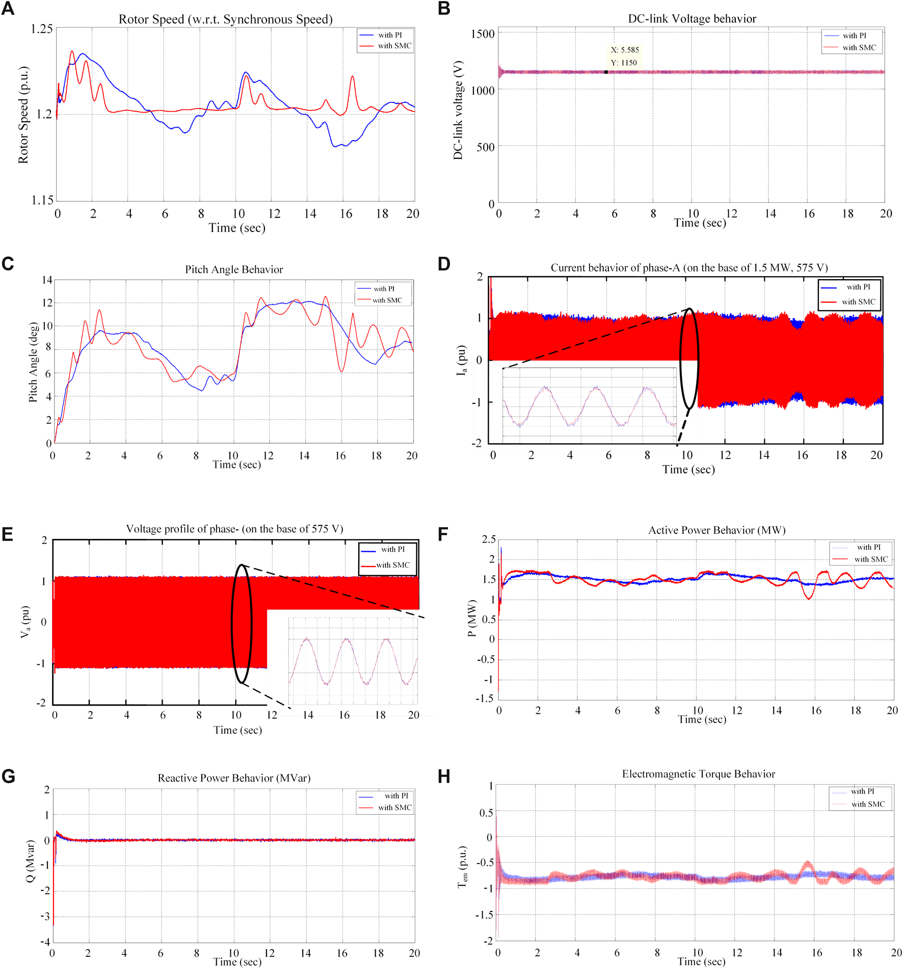
Results showing the comparative behavior of the SMC based speed control with respect to the conventional PI control in terms of (A) machine rotor speed; (B) DC-link voltage; (C) Pitch angle; (D) voltage profile of phase-A; (E) current profile of phase-A; (F) active power behavior; (G) reactive power; and (H) electromagnetic torque.
6 Conclusion
In this work, the sliding mode control (SMC) is investigated for speed control of a doubly fed induction generator (DFIG). The nonsingular fast terminal sliding mode control (NSFTSMC) was applied in the speed loop of the rotor side vector control of DFIG. The proposed NSFTSMC scheme results in less speed fluctuation with a change in wind speed, which is maintained by controlling the torque component of the current (). This paper also presented a detailed modeling of the DFIG, power converters, and the related control schemes. Moreover, stability analysis of the proposed methodology ensured the practical finite time stability of the overall system. The comparative controller performance and validation was carried out in Matlab/Simulink environment. The proposed control strategy presented much better rotor speed results than conventional PI-based control. With further exploration this technique can be implemented in the faster inner loops of the rotor and grid side controllers, which may enhance the dynamics of the electrical behavior of the machine.
Statements
Data availability statement
The original contributions presented in the study are included in the article/supplementary material, further inquiries can be directed to the corresponding author.
Author contributions
MA contributed to conception, methodology, and design of the study. MA and SA carried out the formal analysis. MA organized the database and software coding. SA and MA performed the mathematical analysis and theoretical investigation. MA realized the numerical results. MA wrote the first draft of the manuscript. MA, SA, and MK wrote sections of the manuscript. MK supervised this work. MK provide the laboratory resources. MK arranged the funding acquisition. All authors contributed to manuscript revision, read, and approved the submitted version.
Funding
The research is funded in part by the Interdisciplinary Research Center for Renewable Energy and Power Systems (IRC-REPS) at KFUPM under Project No. INRE2106.
Acknowledgments
The authors would like to acknowledge the support provided by the K. A. CARE Energy Research and Innovation Center and SDAIA-KFUPM Joint Research Center for Artificial Intelligence (JRC-AI) at the King Fahd University of Petroleum and Minerals (KFUPM), Dhahran 31261, Kingdom of Saudi Arabia.
Conflict of interest
The authors declare that the research was conducted in the absence of any commercial or financial relationships that could be construed as a potential conflict of interest.
Publisher’s note
All claims expressed in this article are solely those of the authors and do not necessarily represent those of their affiliated organizations, or those of the publisher, the editors and the reviewers. Any product that may be evaluated in this article, or claim that may be made by its manufacturer, is not guaranteed or endorsed by the publisher.
Nomenclature
Symbol
description
and R Power coefficient, tip ratio, pitch angle and radius of wind turbine
, Stator side voltages and currents
, Rotor side voltages and currents
, , Stator side voltages, currents, and flux linkages in domain
, , Rotor side voltages, currents, and flux linkages in domain
, Angular position of the wind turbine and equivalent angular position of generator-gearbox
, Rotor angular position and its reference value
- Te, TL
Electromagnetic and load torque
Lyapunov function
References
1
Abu-Rub H. Malinowski M. Al-Haddad K. (2014). Power electronics for renewable energy systems, transportation and industrial applications. 1st ed. Wiley. 10.1002/9781118755525
2
Ahmad F. Alam M. S. Shahidehpour M. (2019). Profit maximization of microgrid aggregator under power market environment. IEEE Syst. J.13, 3388–3399. 10.1109/jsyst.2018.2829343
3
Amrr S. M. Ahmad J. Waheed S. A. Sarwar A. Saidi A. S. Nabi M. (2022). Finite-time adaptive sliding mode control of a power converter under multiple uncertainties. Front. Energy Res.580. 10.3389/fenrg.2022.901606
4
Amrr S. M. Alturki A. (2021). Robust control design for an active magnetic bearing system using advanced adaptive smc technique. IEEE Access, 9, 155662–155672. 10.1109/ACCESS.2021.3129140
5
Amrr S. M. Nabi M. (2019). Attitude stabilization of flexible spacecraft under limited communication with reinforced robustness. Trans. Inst. Meas. Control41 (16), 4475–4487. 10.1177/0142331219860651
6
Amrr S. M. Nabi M. (2020). Finite-time fault tolerant attitude tracking control of spacecraft using robust nonlinear disturbance observer with anti-unwinding approach. Adv. Space Res.66 (7), 1659–1671. 10.1016/j.asr.2020.06.019
7
Amrr S. M. Srivastava J. P. Nabi M. (2020). Robust attitude stabilization of spacecraft under constrained network with hysteresis quantizer. IEEE J. Miniat. Air Space Syst.2 (3), 129–139. 10.1109/jmass.2020.3039977
8
Anaya-Lara O. Jenkins N. Ekanayake J. Cartwright P. Hughes M. (2009). Wind energy generation: modeling and control. UK: John Wiley & Sons.
9
Asaad M. Ahmad F. Alam M. S. Sarfaraz M. (2021). Smart grid and indian experience: a review. Resour. Policy74, 101499. 10.1016/j.resourpol.2019.101499
10
Ayedin E. Polat A. Ergene L. T. (2016). “Vector control of dfig in wind power applications,” in ICRERA-2016, 478–483. 10.1109/ICRERA.2016.7884383
11
Bose B. K. (2002). Modern power electronics and ac drives. Upper Saddle River, New Jersey, USA: Prentice Hall PTR.
12
Bou-Rabee M. Lodi K. A. Ali M. Ansari M. F. Tariq M. Sulaiman S. A. (2020). One-month-ahead wind speed forecasting using hybrid ai model for coastal locations. IEEE Access8, 198482–198493. 10.1109/ACCESS.2020.3028259
13
Boukhezzar B. Siguerdidjane H. (2011). Nonlinear control of a variable-speed wind turbine using a two-mass model. IEEE Trans. Energy Convers.26 (1), 149–162. 10.1109/tec.2010.2090155
14
Chojaa H. Derouich A. Chehaidia S. E. Zamzoum O. Taoussi M. Elouatouat H. (2021). Integral sliding mode control for dfig based wecs with mppt based on artificial neural network under a real wind profile. Energy Rep.7, 4809–4824. 10.1016/j.egyr.2021.07.066
15
Elkington K. Ghandhari M. (2009). “Comparison of reduced order doubly fed induction generator models for nonlinear analysis,” in IEEE Electrical Power & Energy Conference, 1–6. 10.1109/EPEC.2009.5420984
16
Fu C. Wang Q. G. Yu J. Lin C. (2021). Neural network-based finite-time command filtering control for switched nonlinear systems with backlash-like hysteresis. IEEE Trans. Neural Netw. Learn. Syst.32 (7), 3268–3273. 10.1109/tnnls.2020.3009871
17
Hu J. Nian H. Hu B. He Y. Zhu Z. Q. (2010). Direct active and reactive power regulation of dfig using sliding-mode control approach. IEEE Trans. Energy Convers.25 (4), 1028–1039. 10.1109/tec.2010.2048754
18
Khalil H. K. (2014). Nonlinear systems. Upper Saddle River, New Jersey, USA: Prentice-Hall.
19
Krause P. C. Wasynczuk O. Sudhoff S. D. Pekarek S. D. (2013). Analysis of electric machinery and drive systems. 3rd ed.Wiley.
20
Li H. Chen Z. (2008). Overview of different wind generator systems and their comparisons. IET Renew. Power Gener.2 (2), 123–138. 10.1049/iet-rpg:20070044, No
21
Miller N. Price W. Sanchez-Gasca J. (2003). Dynamic modeling of ge 1.5 and 3.6 wind turbine-generators for stability simulations. Ontario: IEEE Power Engineering Society General Meeting. 10.1109/PES.2003.1267470
22
Muyeen S. M. Ali M. H. Takahashi R. Murata T. Tamura J. Tomaki Y. et al (2007). Comparative study on transient stability analysis of wind turbine generator system using different drive train models. IET Renew. Power Gener.1 (2), 131–141. 10.1049/iet-rpg:20060030
23
Necoechea-Porras P. D. López A. Salazar-Elena J. C. (2021). Deregulation in the energy sector and its economic effects on the power sector: a literature review. Sustainability13 (6), 3429. available. 10.3390/su13063429
24
Neto A. S. Ferreira S. L. A. Arruda J. P. Neves F. A. S. Rosas P. A. C. Cavalcanti M. C. (2007). Reduced order model for grid connected wind turbines with doubly fed induction generators. IEEE Int. Symposium Industrial Electron., 2655–2660. 10.1109/ISIE.2007.4375027
25
Ontiveros L. J. Mercado P. E. Suvire G. O. (2010). “A new model of the double-feed induction generator wind turbine,” in 2010 IEEE transmission and distribution conference and exposition, Sao Paulo. 10.1109/TDC-LA.2010.5762892
26
Patel M. R. Beik O. (2021). Wind and solar power systems: design, analysis, and operation. 3rd ed. Florida, USA: CRC Press.
27
Pena R. Clare J. C. Asher G. M. (1996). A Doubly fed induction generator using back-to-back pwm converters supplying an isolated load from a variable speed wind turbine. IEE Proc. Electr. Power Appl.143 (5), 380–387. 10.1049/ip-epa:19960454
28
Qiao W. Zhou W. Aller J. M. Harley R. G. (2008). Wind speed estimation based sensorless output maximization control for a wind turbine driving a dfig. IEEE Trans. Power Electron.23 (3), 1156–1169. 10.1109/tpel.2008.921185
29
Slootweg J. G. de Hann S. W. H. Polinder H. Kling W. L. (2003). General model for representing variable speed wind turbines in power system dynamics simulations. IEEE Trans. Power Syst.18 (1), 144–151. 10.1109/tpwrs.2002.807113
30
Subudhi B. Ogeti P. S. (2018). Optimal preview stator voltage-oriented control of dfig wecs. IET Gener. Transm. &. Distrib.12 (4), 1004–1013. 10.1049/iet-gtd.2016.2027
31
Tapia A. Tapia G. Ostolaza J. X. Sáenz J. R. (2003). Modeling and control of a wind turbine driven doubly fed induction generator. IEEE Trans. Energy Convers.18 (2), 194–204. 10.1109/tec.2003.811727
32
Tiwari P. M. Janardhanan S. Masuq-un-Nabi. (2012). Spacecraft attitude control using non-singular finite time convergence fast terminal sliding mode. Int. J. Instrum. Technol.1 (2), 124–142. 10.1504/ijit.2012.053289
33
Utkin V. Guldner J. Shi J. (2017). Sliding mode control in electro-mechanical systems. 2nd ed. Boca Raton: CRC Press. 10.1201/9781420065619
34
Yang L. Yang J. (2011). Nonsingular fast terminal sliding‐mode control for nonlinear dynamical systems. Int. J. Robust Nonlinear Control21 (16), 1865–1879. 10.1002/rnc.1666
35
Zadehbagheri M. Ildarabadi R. Nejad M. B. (2013). Sliding mode control of a doubly-fed induction generator (dfig) for wind energy conversion system. Int. J. Sci. Eng. Res.4 (11), 1573–1581.
36
Zhu Z. Xia Y. Fu M. (2011). Attitude stabilization of rigid spacecraft with finite‐time convergence. Int. J. Robust Nonlinear Control21 (6), 686–702. 10.1002/rnc.1624
Summary
Keywords
DFIG (double fed induction generator), sliding mode control, wind energy system, field oreinted control, MPPT, pitch angle control
Citation
Ali M, Amrr SM and Khalid M (2022) Speed control of a wind turbine–driven doubly fed induction generator using sliding mode technique with practical finite‐time stability. Front. Energy Res. 10:970755. doi: 10.3389/fenrg.2022.970755
Received
16 June 2022
Accepted
01 August 2022
Published
13 September 2022
Volume
10 - 2022
Edited by
Saad Mekhilef, Swinburne University of Technology, Australia
Reviewed by
Salman Ahmad, Islamic University of Science and Technology, India
Asaad Mohammad, Auckland University of Technology, New Zealand
Furkan Ahmad, Hamad bin Khalifa University, Qatar
Md Reyaz Hussan, Qatar University, Qatar
Updates
Copyright
© 2022 Ali, Amrr and Khalid.
This is an open-access article distributed under the terms of the Creative Commons Attribution License (CC BY). The use, distribution or reproduction in other forums is permitted, provided the original author(s) and the copyright owner(s) are credited and that the original publication in this journal is cited, in accordance with accepted academic practice. No use, distribution or reproduction is permitted which does not comply with these terms.
*Correspondence: Muhammad Khalid, mkhalid@kfupm.edu.sa
This article was submitted to Smart Grids, a section of the journal Frontiers in Energy Research
Disclaimer
All claims expressed in this article are solely those of the authors and do not necessarily represent those of their affiliated organizations, or those of the publisher, the editors and the reviewers. Any product that may be evaluated in this article or claim that may be made by its manufacturer is not guaranteed or endorsed by the publisher.