 Fengqin Li
 Lulu Zhai
 Baoling Cui
 Zuchao Zhu1
- 1State-province Joint Engineering Laboratory of Fluid Transmission System Technology, Zhejiang Sci-Tech University, Hangzhou, China
- 2Zhejiang Institute of Mechanical and Electrical Engineering Co., Ltd., Hangzhou, China
A transient computational fluid dynamics (CFD) method based on dynamic mesh is adopted to investigate the static and dynamic performances of an annular seal with a tilted rotor. The reliability of the CFD method is verified by the experimental data, and then the variations of dynamic performance and sealing performance under different length-diameter ratios and misalignment angles are investigated by the method. The results show that the leakage flowrate of the tilted annular seal decreases with the increasing length-diameter ratio, while the whirl frequency ratio increases with the length-diameter ratio. The increase of misalignment angle has little detrimental effect on the stability of long shaft system in the three misalignment modes. In addition, the misalignment mode for the tilted position at the half-length of the annular seal can reduce the leakage flowrate.
1 Introduction
Centrifugal pumps are the core device for fluid transportation and are widely used in aerospace, petrochemical, and nuclear power industries. An annular seal is a critical component in centrifugal pumps, reducing the leakage flow through the clearance between the stationary and rotating parts from the high-pressure region to the low-pressure region (Childs, 1993; Childs and Vance, 1997; Wang et al., 2019). The annular seal is like a sliding bearing in structure, consisting of a fixed outer ring and an inner rotating part. However, the clearance of the annular seal is larger than that of the sliding bearing, and there is a large pressure difference between the inlet and outlet of the seal. The fluid in the annular clearance is in a highly turbulent state under the dual driving of pressure difference and rotor rotation, which is completely different from the fluid state in the sliding bearing. Although the flow mechanism is different, the annular seal shows a similar supporting effect to the sliding bearing, and can also induce whirl instability of the rotor components (Brennen and Acosta, 2006; Vance, et al., 2010). The dynamic performances of the annular seal are directly related to the vibration characteristics and stability of the centrifugal pump rotor system, which makes the research on the dynamic characteristics of the annular seal become a hotspot.
For decades, scholars put forward lots of methods to investigate the dynamic performance of annular seals. Childs (1983) first conducted a finite-length solution on an annular plain seal with the bulk-flow method, which has become the most commonly method applied in industry. Nelson and Nguyen (1988a); Nelson and Nguyen, (1988b) raised a new analytical method different from Child’s method by applying fast fourier transforms to investigate the effect of eccentric ratio on the dynamic performance of a plain seal. After that, Iwatsubo et al. (1996) adopted a two-control-volume method to predict the dynamic coefficients of a liquid seal with double spiral grooves on the rotor surface. Wyssmann et al. (1984) modified the two-control-volume method and used it for a labyrinth gas seal. To describe flow state in labyrinth seals more realistically, Marquette and Childs (1996) proposed a three-control-volume approach for a liquid circumferentially grooved seal, which had high prediction accuracy for both leakage flowrate and dynamic coefficients. In recent years, with the improvement of computer technology, CFD methods have become popular and effective methods to predict the dynamic coefficient of annular seals. Dietzen and Nordmann, (1987) first introduced the CFD method for an annular seal by using rotor fixed coordinates and perturbation analysis. Then, Tam et al. (1988) raised a quasi-steady CFD method which transformed a transient problem in a stationary frame to a steady one by introducing a moving reference frame attached to a whirl rotor. However, the introduction of quasi-steady simplification would cause additional error to the analysis results. Thus, a transient CFD method that directly solving the flow field in stationary frame was performed by Williams et al. (1997), and the method could obtain time-varying fluid forces. Subsequently, the transient numerical analysis for the dynamic of annular seals were performed by many scholars, including Wu et al. (2016), Li et al. (2013; 2020), Chochua and Soulas (2007), and Xu et al. (2018).
The above research on the annular seals was carried out for the case where the central axis of the rotor is parallel to that of the stator. However, the rotor would tilt with a certain amount in high-performing rotating machinery with heavy radial loads. Iino and Kaneko, (1980) discovered the inclination between the rotor and stator axes has a significant impact on fluid excitation forces of annular seals. Fenwick et al. (1982) firstly calculated the dynamic coefficients for a short-length annular seal under rotor misalignment conditions, and the authors revealed that the excitation forces generated by the misalignment were as significant as translation. Then, Chen and Jackson, (1985) also investigated the fluid excitation forces induced by large shaft angular motions for short seals, and revealed the seal dynamic performance changed considerably in high misalignment condition, particularly when the perturbation direction coincided with the minimum clearance. Childs (1982) mentioned the dynamic coefficients due to shaft angular displacements are also crucial in annular seals having characteristics of large length-diameter (L/D) ratio, especially in submerged pumps. The moment coefficients due to shaft misalignment angles were obtained by Askharone and Hensel, (1991) through finite element methods. It was shown that the increase of rotor speed would improve the dynamic stability of shaft angular motions. San Andres (1993) utilized the bulk-flow model to study the effects about rotor misalignments on the dynamic propriety of liquid annular seals. The results revealed the misalignments at seal inlet can enhance the support effects of liquid film, while the misalignments at seal outlet can descend the support effects of liquid film. Scharrer et al. (1993) also found the misalignment at the seal inlet can produce large force stiffening effects.
At present, the prediction of dynamic and static performances of tilted annular seals chiefly adopts the bulk-flow method, and rarely involves CFD methods. In the current paper, a transient CFD method is applied to simulate whirling motion of an annular seal with a tilted rotor, and the prediction accuracy of the method is examined by the experiments and the bulk-flow method. Then the influences of length-diameter ratio, static misalignment angle, misalignment mode, pressure difference and rotational speed on the static and dynamic performances of the annular seal are explored by the transient CFD method.
2 Numerical geometric structure and computational fluid dynamics method
2.1 The numerical information of the annular seal
Figure 1A depicts the seal used in the paper, which is based on Kanemori’s experimental model (Kanemori and Iwatsubo, 1994). The geometric information and simulation information of the annular seal are shown in Table 1. The medium used for the annular seal is water at room temperature. The whole fluid domain is divided by structured grids, as shown in Figure 1B. Three misalignment modes of the seal are presented in Figure 2. The planes where the rotor axis passes through the seal entrance section, Z = 0, the quarter section, Z = L/4, and the middle section, Z = L/2, are defined as mode 1, mode 2, and mode 3, respectively. The grid independence is examined by comparing the fluid excitation forces at different grid densities based on the mode 3 with a misalignment angle of 3.3e-4 radians. It can be seen from Figure 3 that when mesh number comes up to 3.061 million, the fluid excitation forces (Fr and Ft) change little with the further increasing mesh number. Therefore, the mesh number of 3.061 million is chosen to perform the transient CFD simulations in this paper.
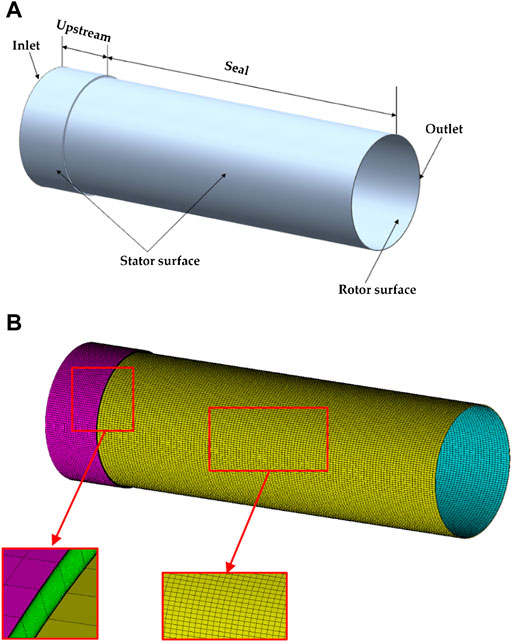
FIGURE 1. The annular seal. (A) The model. (B) The grid.
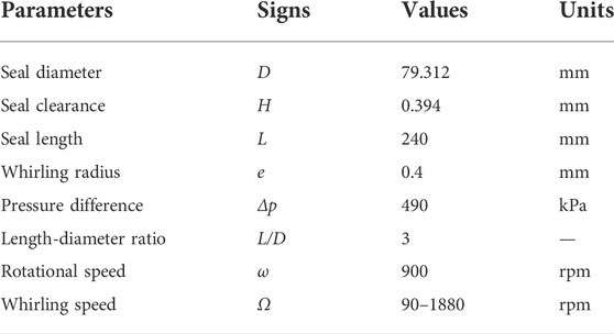
TABLE 1. The geometrical dimensions and operating conditions of the seal (Kanemori and Iwatsubo, 1994).
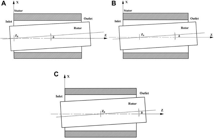
FIGURE 2. The diagram of three misalignment modes of the annular seal: (A) Mode 1; (B) Mode 2; (C) Mode 3.
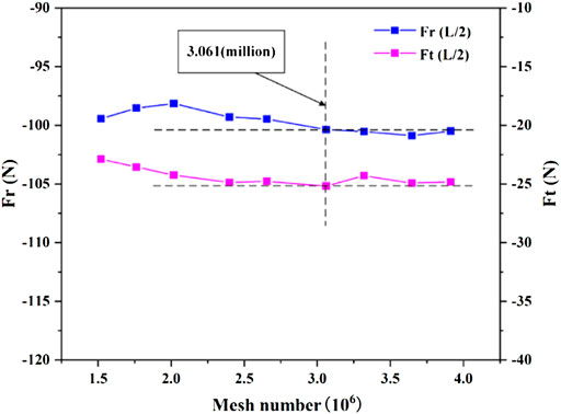
FIGURE 3. Grid independence analysis.
2.2 Transient computational fluid dynamics method for dynamic mesh
The rotor whirls in the annular seal, causing the clearance shape to change over time. Note that this is a transient problem, which requires dynamic mesh technique to resolve it. In this paper, the dynamic mesh technique is performed by self-compiled program through the macro Define_Grid_Motion. There are three different misalignment modes of the annular seal studied in the paper. For the sake of concise, the misalignment mode 2 shown in Figure 2 is acted as a case to illustrate the grid movement process in the clearance of the annular seal. The grid movement process is as follows.
Figure 4A presents mesh movement in radial clearance at arbitrary axial section of the seal. The clearance has been magnified to clearly illustrate the grid movement. As shown in the figure, before the rotor whirls, the rotor center coincides with the stator center, that is, the rotor is at the homocentric position O. When the rotor whirls, the rotor center deviates from the stator center, that is, the rotor center moves from the homocentric position O to the eccentric position O1, and at the same time, point A on the rotor surface moves to point A1. Q is a point on the stator surface, which remains stationary, and any point G (xG, yG) in the clearance moves to point G1 (xG1, yG1) to ensure that the point G is located on the grid line A1Q1 after the rotor whirls. During the whirling motion, the moving displacement of the rotor at each time step is d (xd, yd), and the moving displacement of arbitrary point G in the clearance is obtained by interpolation method (Jiang, 2016), as shown in Eq. 1.
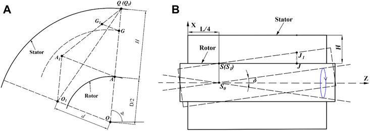
FIGURE 4. The grid movement of the seal fluid domain during transient CFD simulation. (A) Grid movement in the radial direction of the seal. (B) Grid movement in the axial direction of the seal.
When the rotor locates in the homocentric position, Fa can be represented by the coordinates of point G, as shown in Eq. 2.
When the rotor locates in an eccentric position, Fa is represented by the coordinates of point G1, the rotor whirling displacement d and the initial angular displacement ψ of point G, as shown in Eq. 3. Therefore, the rotor whirls one step, the nodes in the clearance also move to the corresponding position to guarantee the optimum mesh quality.
It can be seen from the above analysis that if the whirling displacement d (xd, yd) of the rotor is obtained, the displacement of the nodes in the clearance can be calculated. The whirling motion is presented in Figure 4B. When the rotor moves from the coaxial position with the stator to the tilted position, the arbitrary point J (xj,yj) on the rotor surface is moved to point J1 and the axial misaligned angle is δ (δx, δy). Since point S0 is the tilted point of the rotor, point S remain stationary after misalignment. The mathematical model of the whirling motion is described in Eq. 5, and the whirling trajectory is represented by the blue circle, as shown in Figure 4B. As can be seen from the figure, the whirl radius is different along the axial direction. Therefore, the moving displacement of any point J needs to be expressed by the axial coordinate of the point and the whirling time, as shown in Eq. 6.
Figure 5 shows the flow diagram for performing transient calculations. Before the calculation of the transient flow field of the annular seal, a steady-state calculation is carried out to eliminate the influence of the initial value on the transient result, and then the steady result is used as the initial condition to start the transient calculation. During the transient simulation, Fluent reads the rotor whirl displacement signal through the macro Define_Grid_Motion to determine the latest position of the shaft center and update the coordinates of all grids in the fluid domain. In addition, since the position of the rotor center is constantly changing during the transient calculation, the rotation speed of the rotor surface cannot be set according to the method of rotating around a fixed axis. In this paper, the coordinates of the nodes on the rotor surface are read by the macro Define_Profile. According to the coordinates, the tangential velocity of the nodes on the rotor surface can be decomposed into the X-direction velocity component Vx and the Y-direction velocity component Vy, and then assign the two velocity components to the nodes through the macro Define_Profile.
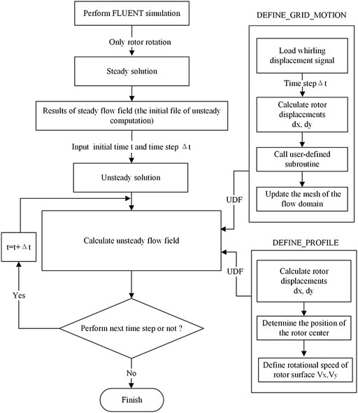
FIGURE 5. Calculation diagram of transient flow field.
Fluent 18.0 is applied to calculate the three-dimensional incompressible fluid field of the annular seal. Total pressure and static pressure are separately set at the seal inlet and outlet. Table 2 compares the CFD predicted excitation forces of different turbulence models with the experimental results (Kanemori and Iwatsubo, 1994) under the rotational speed of 900rpm and the pressure difference of 490 kPa. It can be concluded that the realizable k-ε model with enhanced wall treatment is a better choice for the current CFD calculations. Time term is discretized by first-order implicit schemes, and the rotor rotating for one degree is used as time step. The convection term and diffusion term are separately discretized by second-order upwind schemes and central difference schemes. The pressure-velocity coupling is coped with by the SIMPLE algorithm.
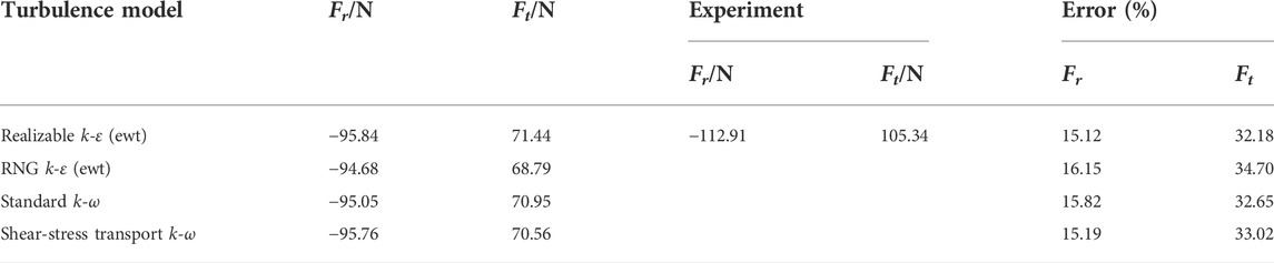
TABLE 2. The fluid excitation forces of different turbulence models.
The convergence target for each steady solution is that the residuals of the continuity equations, momentum equations, and turbulence equations reach 10−6. For the transient solution, the convergence target of each simulation is that the residuals of the continuity equations, momentum equations and turbulence equations reach 10−5, and the fluid excitation forces (Fx, Fy) on the rotor surface are periodic and the fluctuations of the forces between adjacent periods are less than 0.2%. On the hardware side, an Inter(R) Xeon(R) Gold 5220 2.20 GHz CPU computer with 64 RAM is used. The computation time for each whirl speed is approximately 34 h. Six whirl speeds are performed to solve the five dynamic coefficients, and the total calculation time is about 204 h.
2.3 Extraction of dynamic coefficients
The inclination between the axial lines of a rotor and a stator causes the rotor perturbed with a tilting whirling motion. The tilting whirling model is defined as Eq. 5. For small whirling of a rotor around arbitrary positions, fluid excitation forces are described by dynamic coefficients (Childs, 1982), as presented in Eq. 7. Kα and kα are direct stiffness and cross-coupled stiffness, respectively, Cα and cα are direct damping and cross-coupled damping, respectively, Mα is direct virtual-mass. According to the relationship between the static reference frame and the moving reference frame, the fluid excitation forces (Fx, Fy) in Eq. 7 can be redefined by Eq. 8. If Ω is changed, the fluid excitation forces (Fr, Ft) corresponding to Ω are determined by integrating the pressure on the rotor surface. Since there are three known parameters (Fr, Ft and Ω) and five unknowns (Kα, cα, Mα, kα, Cα) in the Eq. 8, so it needs at least 5 transient CFD calculations to identify all unknown coefficients.
3 Results and discussion
3.1 The verification of the transient computational fluid dynamics method
Figure 6 compares the fluid excitation forces of the transient CFD method with those of the experiment and the bulk-flow method to check the reliability of the current CFD method (Kanemori and Iwatsubo, 1994). The transient CFD simulations are carried out based on the mode 3 with a misalignment angle of 3.3e-4 radians under the rotational speed of 1080 rpm and the pressure difference of 840 kPa. The transient CFD method is found to predict tangential forces Ft with almost the same accuracy as the bulk-flow method, both of which are more than the experimental result, and the maximal error is 26.7%. Note that the prediction accuracy of the transient CFD method for the radial force Fr is apparently superior to that of the bulk-flow method. The radial force obtained by the CFD method almost coincides with the experimental result in the range of
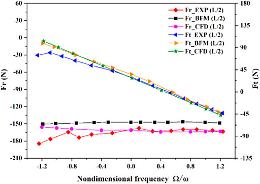
FIGURE 6. Comparison of fluid excitation forces of the transient method with those of the Kanemori and Childs (Kanemori and Iwatsubo, 1994).
3.2 The dynamic and static performances of tilted annular seal with various length-diameter ratios
To study the relationship between the dynamic performance and the length of the tilted annular seal, the length is changed from 1.6e-4 m (L/D = 0.2) to 0.4 m (L/D = 5) with the other boundary conditions unchanged. The investigation is carried out based on the mode 3 with a misalignment angle of 3.3e-4 radians. Figures 7, 8 plot the tilting dynamic performance versus the seal length-diameter ratio (L/D) at different rotational speeds and pressure differences. It is observed that direct stiffness coefficients and direct damping coefficients under differences rotational speeds of the three pressure differences are sensitive to L/D ratio, and both increase with L/D ratio. When L/D ratio is less than 2, direct stiffness coefficients and direct damping coefficients under three different pressure differences are insensitive to rotational speed. As L/D ratio further increases, the larger rotational speed obtains the larger direct stiffness coefficient, especially under the condition of 250 kPa. However, the variation trends of direct damping coefficients under the three pressure differences with rotational speed are opposite to those of direct stiffness coefficients with rotational speed. Additionally, under the same L/D ratio conditions, direct stiffness coefficients and direct damping coefficients at three rotational speeds all increase with pressure difference. For cross-coupled stiffness coefficients and cross-coupled damping coefficients under different rotational speeds of the three pressure differences, L/D ratio has little influence on these two coefficients when L/D ratio is less than 1. As L/D ratio gradually increases, cross-coupled stiffness coefficients and cross-coupled damping coefficients increase with L/D ratio, and the higher rotational speed possess the larger cross-coupled stiffness coefficient and cross-coupled damping coefficient. Note that the growths of cross-coupled damping coefficients under 1500rpm of three differential pressures are dramatically greater than those under the other two rotational speeds. It is also observed that under the same L/D ratio conditions, cross-coupled stiffness coefficients at the three rotational speeds increase with the increasing pressure difference. Except for the condition of 1500rpm, cross-coupled damping coefficients of different rotational speeds also increase with pressure difference. In general, L/D ratio has great effect on dynamic coefficients of tilted annular seals, and ignoring tilting dynamic performance will greatly underestimate fluid excitation forces acting on a rotor, especially for large L/D ratio. Therefore, in the dynamic analysis of rotor systems, the influences of tilting disturbance on fluid excitation forces of annular seals should be reasonably considered according to the seal length.
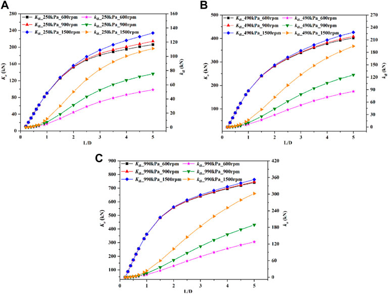
FIGURE 7. The variations of stiffness coefficients with length-diameter ratio under different pressure differences and rotational speeds. (A) 250 kPa. (B) 490 kPa. (C) 990 kPa.
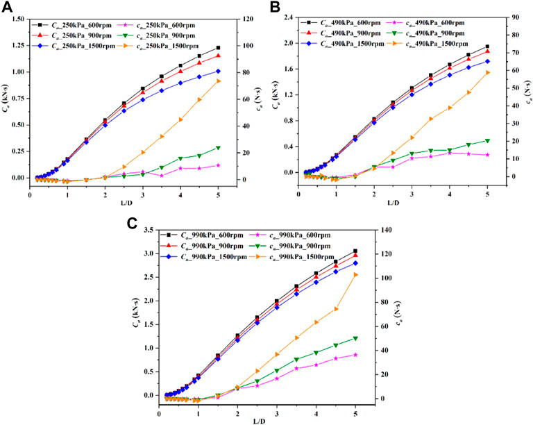
FIGURE 8. The variations of damping coefficients with length-diameter ratio under different pressure differences and rotational speeds. (A) 250 kPa. (B) 490 kPa. (C) 990 kPa.
To better illustrate dynamic behavior of annular seals, the whirl-frequency ratio f is commonly used to weigh the stability of rotor systems, which should be as small as possible to guarantee the safe operation of the systems. The whirl-frequency ratio consists of the two key coefficients of cross-coupled stiffness and direct damping, and is often estimated under the assumption of synchronous whirl (Iwatsubo and Ishimaru, 2010). It is observed from Figure 9 that the whirl-frequency ratios under the three pressure differences increase with the increasing L/D ratio. As for Figure 9A, when L/D ratio increases from 0.2 to 5, the whirl-frequency ratio increases the least at 250 kPa and the most at 990kPa, which are 351.3% and 584.3%, respectively. And when L/D ratio is 5, the whirl-frequency ratios of the two pressure differences are 0.73 and 0.65, respectively. This phenomenon indicates that a large L/D ratio seriously reduces the stability of rotor systems. This is because the annular seal, due to its long structure, will generate additional centrifugal force during high-speed operation, causing the shaft to flex and deform. When there is flexural deformation, the helical flow effect of the fluid in the seal will be intensified (He and Xia, 1999), leading to the rotor whirling and reducing the stability of the rotor system. For Figures 9B,C, the variations of the whirl-frequency ratios with the pressure difference show patterns like that discussed in Figure 9A. However, the rotational speed has little effect on the whirl-frequency ratio compared with pressure difference.
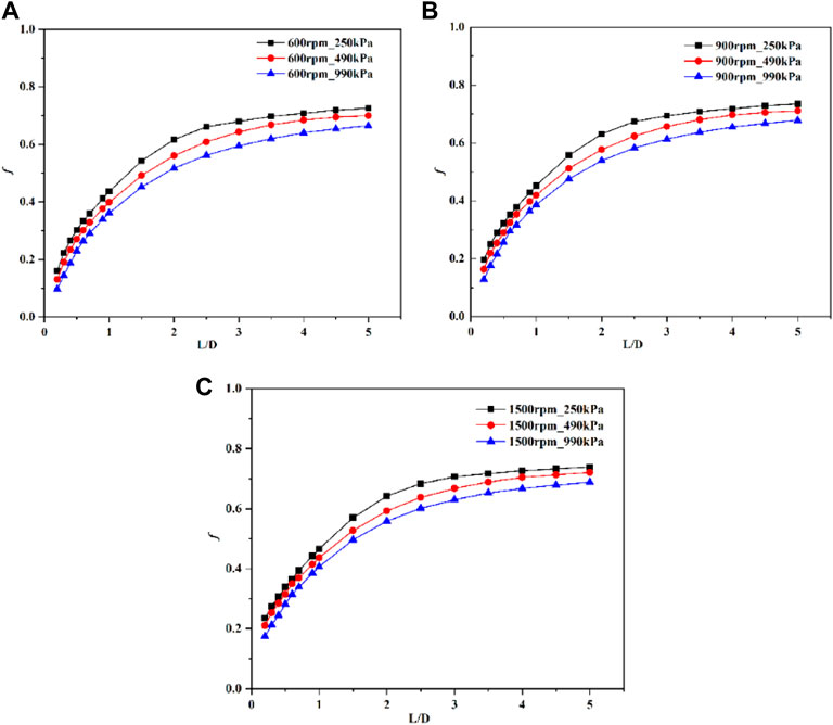
FIGURE 9. The variations of whirl-frequency ratios with length-diameter ratio under different pressure differences and rotational speeds. (A) 600rpm. (B) 900rpm. (C)1500rpm.
Figure 10 demonstrates that leakage flowrates under different pressure differences decrease exponentially as L/D ratio increases. Note that under the same L/D ratio conditions, leakage flowrate is sensitive to changes in pressure difference, but not to rotational speed. When L/D ratio is 0.2, the leakage flowrates at 250, 490 and 990 kPa are 1.65 kg/s, 2.36 kg/s and 3.43 kg/s, respectively, and then decrease to 0.37 kg/s, 0.59 kg/s and 0.93 kg/s, respectively, as L/D ratio increases to 5. Therefore, the analysis shows that long annular seal with tilted rotor can effectively reduce leakage flowrate, especially under low pressure difference. The theoretical calculation formula of leakage flowrate Q of annular seals is generally shown as follow (Tarudanavski et al., 1986; Hu et al., 2021),
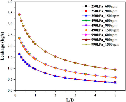
FIGURE 10. The variations of leakage flowrates with length-diameter ratio under different pressure differences and rotational speeds.
The seal length L is inversely proportional to the leakage flowrate Q, which also indicates that increasing the seal length can reduce the leakage flowrate.
3.3 The dynamic and static performances of long annular seal under different static misalignment angles
It is seen from Section 3.2 that the dynamic performance due to shaft angular displacement are important in long annular seals. Therefore, in this section, an annular seal with a length-diameter ratio of 3 is applied to investigate the effect of static misalignment angle on the dynamic performance of the seal. Three different misalignment modes are selected for this study, as shown in Figure 2. The misalignment angle δ denotes the angle between the rotor axis and the stator axis, which increases from 0 radians to the maximum value of 0.00148 radians. When the rotor axis passes through the seal entrance plane (the mode 1), the largest misalignment angle (δ= 0.00148 radians) corresponds to a 90% shaft displacement relative to the radial clearance on the opposite side of the seal. Figure 11 presents the effect of static misalignment angle on direct stiffness coefficient. The pressure differences under three Y-axes in the figures denote that these dynamic coefficients are obtained at the corresponding pressure differences. It can be observed that direct stiffness coefficients of three misalignment modes at different pressure differences ranging from 250 to 990 kPa increase as the static misalignment angle increases, especially at 1500rpm. Under the same rotational speeds and pressure differences, the mode 1 possesses the largest direct stiffness coefficient, followed by the mode 2 and then the mode 3. But noted that in Figure 11C, when operating at pressure differences of 250kPa and 490 kPa under a speed of 1500rpm, the mode 1 has the minimum direct stiffness coefficients and the mode 3 has the maximum ones. This is because under high-speed and low-pressure difference conditions, when rotor axis passes through seal plane closer to the seal inlet, the lateral motion plays a dominant role in the seal, resulting in a large negative direct stiffness coefficient. The figure also illustrates that under the same rotational speed conditions, the direct stiffness coefficients of the three modes increase with the increasing pressure difference, while under the same pressure difference conditions, except for the mode 3, the direct stiffness coefficients of the other modes decrease with the increasing rotational speed.
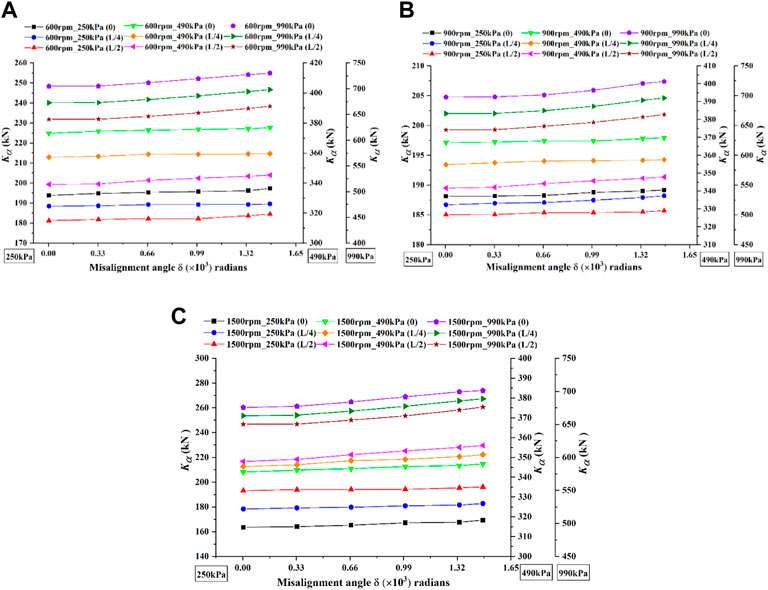
FIGURE 11. The variations of direct stiffness with misalignment angle under different pressure differences and rotational speeds. (A) 600rpm. (B) 900rpm. (C) 1500rpm.
Cross-coupled stiffness coefficient versus misalignment angle is demonstrated in Figure 12. It is observed that cross-coupled stiffness coefficients under different pressure differences are insensitive to misalignment angle for the misalignment mode 3. However, the cross-coupled stiffness coefficients of the other modes increase with misalignment angle. When the misalignment angle is increased from 0 to 0.00148 radians, under the same pressure differences and rotational speeds, the growths of cross-coupled stiffness coefficients for the mode 1 are larger than those of the cross-coupled stiffness coefficients for the mode 2. It is also observed that under the same rotational speeds and pressure differences, the mode 1 has the largest cross-coupled stiffness coefficient, followed by the mode 2 and then the mode 3. In addition, when operating under the same rotational speed conditions, the cross-coupled stiffness coefficients of the three modes increase with pressure difference, and when operating at the same pressure difference conditions, the cross-coupled stiffness coefficients of the three modes also increase with rotational speed.
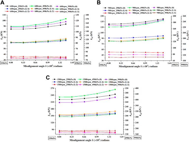
FIGURE 12. The variations of cross-coupled stiffness coefficients with misalignment angle under different pressure differences and rotational speeds. (A) 600rpm. (B) 900rpm. (C) 1500rpm.
Figures 13, 14 illustrate the influence of static misalignment angle on direct damping coefficients and cross-coupled damping coefficients, respectively. Figures show that under different pressure difference conditions, the misalignment angle has no effect on direct damping coefficients and cross-coupled damping coefficients for the mode 3. However, for the mode 1 and the mode 2, direct damping coefficients increase with the increasing misalignment angle, while cross-coupled damping coefficients decrease with the increasing misalignment angle. As the misalignment angle is increased from 0 to 0.00148 radians, under the same rotational speeds and pressure differences, the growths of direct damping coefficients of the mode 1 are greater than those of the mode 2, and for cross-coupled damping coefficients, the decreases of the mode 1 are also larger than those of the mode 2, especially under high rotational speed. Under the same rotational speeds and pressure differences, it is also observed that the misalignment mode 1 has the maximum direct damping coefficient and cross-coupled damping coefficient, followed by the mode 2 and then the mode 3. Additionally, at the same rotational speed conditions, direct damping coefficients of the three modes increase with pressure difference, while cross-coupled damping coefficients are less affected by pressure difference. Under the same pressure difference conditions, direct damping coefficients of the three modes are almost insensitive to rotational speed, while cross-coupled damping coefficients increase as rotational speed increases.
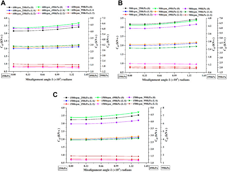
FIGURE 13. The variations of direct damping coefficients with misalignment angle under different pressure differences and rotational speeds. (A) 600rpm. (B) 900rpm. (C) 1500rpm.
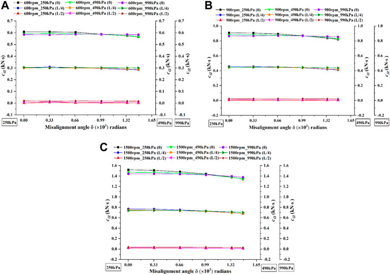
FIGURE 14. The variations of cross-coupled damping coefficients with misalignment angle under different pressure differences and rotational speeds. (A) 600rpm. (B)900rpm. (C) 1500rpm.
Figure 15 demonstrates the effect of misalignment angle on the whirl-frequency ratio. As shown in Figure 15A, under different rotational speed conditions, the whirl-frequency ratios of the mode 2 and the mode 3 are not sensitive to the changes in misalignment angle, while the whirl-frequency ratios of the mode 1 increase as the angle increases. As pressure difference becomes larger, the whirl-frequency ratios of the three modes all increase with the misalignment angle, as presented in Figure 15B and Figure 15C. Note that under different rotational speeds of the three differential pressures, when the misalignment angle is increased from 0 to 0.00148 radians, the maximum growths of whirl-frequency ratios for the mode 1, the mode 2 and the mode 3 are 3.92%, 2.59% and 4.56%, respectively. Therefore, the static misalignment has a little adverse influence on the stability of shaft system, which is similar to the theoretical results of Scharrer et al. (1993) parametric study. According to the small displacement whirl theory (Childs, 1993), the whirl radius e should be less than 10% of the seal clearance. The misalignment angle of the annular seal is changed by adjusting the whirl radius while keeping the seal length L unchanged. The whirl radius e is very small relative to the length L, so the change of the misalignment angle is also small, which explains the reason why the increase of the misalignment angle has less effect on the whirl frequency ratio. Under the same pressure difference and rotational speed conditions, the mode 3 has the largest whirl-frequency ratio, followed by the mode 2 and then the mode 1. Under the same pressure difference conditions, the whirl-frequency ratios of the mode 1 and the mode 2 are not sensitive to rotational speed, while the whirl-frequency ratios of the mode 3 increase with rotational speed. But under the same rotational speed conditions, the whirl-frequency ratios of the three modes all decrease with the increasing pressure difference.
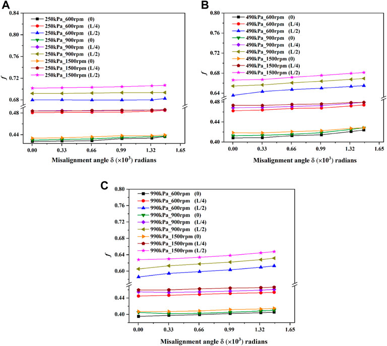
FIGURE 15. The variations of whirl frequency ratios with misalignment angle under different pressure differences and rotational speeds. (A) 250 kPa. (B) 490 kPa. (C) 990 kPa.
The effect of misalignment angle on leakage flowrate is shown in Figure 16. It is observed that under different rotational speeds of the three pressure differences, the leakage flowrates of the mode 1 and the mode 2 increase with increasing misalignment angle, and the growths of the mode 1 are greater than those of the mode 2. However, the leakage flowrates of the mode 3 decrease as the angle increases, especially under high pressure difference. In addition, under the same pressure differences, the leakage flowrates of the three modes decrease with the increase of rotational speed, while under the same rotational speed conditions, the leakage flowrates increase with pressure difference. It is also seen that under the same pressure differences and rotational speeds, the mode 1 leaks the most, followed by the mode 2 and then the mode 3. The analysis shows that both misalignment angle and misalignment mode have great influence on the leakage flow, and the position of misalignment point close to the seal center is helpful to reduce leakage flowrate, especially at the large misalignment angle.
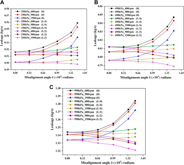
FIGURE 16. The variations of leakage flowrates with misalignment angle under different pressure differences and rotational speeds. (A) 250 kPa. (B) 490 kPa. (C) 990 kPa.
4 Conclusion
In this paper, the static and dynamic performances of a tilted annular seal are studied by the CFD method with dynamic mesh. The reliability of the method is proofed by comparing the CFD results with those of the experiment and the bulk-flow method. Then, the influences of seal length, static misalignment angle and misalignment mode on the static and dynamic performances of the annular seal are explored by the transient CFD method. The following conclusions are drawn.
(1) The current transient numerical simulation has high accuracy in predicting fluid excitation forces of the annular seal with tilted rotor, and this method provides better improvement than the bulk-flow method in predication of the radial fluid excitation force.
(2) The leakage flowrate of the tilted annular seal decreases with the increasing length-diameter ratio, while the whirl frequency ratio increases with the length-diameter ratio, which seriously reduces the stability of the annular seal. Therefore, in the design process of a long annular seal, in order to optimize the performance of pump rotor system without affecting the sealing effect, it can be considered to break the long annular seal, that is, dividing the long annular seal into multiple short seals, which can increase the support stiffness while minimizing the cross-coupled stiffness to improve the stability of rotor system.
(3) The misalignment angle has little effect on the stability of the long shaft system, while the misalignment position at the half-length of the annular seal can reduce leakage flowrate. In the paper, the effects of misalignment angle and misalignment mode on the static and dynamic performances of the long annular seal are investigated, which can provide guidance for practical engineering problems and have reference significance for the theoretical study of annular seals.
Data availability statement
The raw data supporting the conclusions of this article will be made available by the authors, without undue reservation.
Author contributions
LZ and BC conceived of the present idea. ZZ and JG performed the validation. FL conducted the computations and wrote the present paper, All authors discussed the results and contributed to the final manuscript.
Funding
This research was funded by the National Natural Science Foundation of China (Grant No. 51976199 and Grant No. 52076197), the Key Research and Development Program of Zhejiang Province (Grant No. 2020C01027 and Grant No. 2022C03036), Zhejiang Province High-Level Talent Special Support plan (2019R51002) and Advanced Space Propulsion Laboratory of BICE and Beijing Engineering Research Center of Efficient and Green Aerospace Propulsion Technology (LabASP-2021-08).
Conflict of interest
Author JG is employed by the company Zhejiang Institute of Mechanical and Electrical Engineering Co., Ltd.
The remaining authors declare that the research was conducted in the absence of any commercial or financial relationships that could be construed as a potential conflict of interest.
Publisher’s note
All claims expressed in this article are solely those of the authors and do not necessarily represent those of their affiliated organizations, or those of the publisher, the editors and the reviewers. Any product that may be evaluated in this article, or claim that may be made by its manufacturer, is not guaranteed or endorsed by the publisher.
References
Askharone, E. A., and Hensel, S. J. (1991). Interrelated rotordynamic effects of cylindrical and conical whirl of annular seal rotors. J. Tribol. 113, 470–480. doi:10.1115/1.2920648
Brennen, C. E., and Acosta, A. J. (2006). Fluid-induced rotordynamic forces and instabilities. Struct. Control Health Monit. 13, 10–26. doi:10.1002/stc.145
Chen, W. C., and Jackson, E. D. (1985). Eccentricity and misalignment effects on the performance of high-pressure annular seals. A S L E Trans. 28, 104–110. doi:10.1080/05698198508981601
Childs, D. W. (1983). Finite-length solutions for rotordynamic coefficients of turbulent annular seals. J. Lubr. Technol. 105, 437–444. doi:10.1115/1.3254636
Childs, D. W. (1993). “Rotordynamic models for annular gas seals,” in Turbomachinery rotordynamics: Phenomena, modeling, and analysis (New York: John Wiley & Sons), 173–185.
Childs, D. W. (1982). “Rotordynamic moment coefficients for finite-length turbulent seals,” in Proc. Of international conference on rotordynamic problems in power plants, 371–378.
Childs, D. W., and Vance, J. M. (1997). “Annular gas seals and rotordynamics of compressors and turbines,” in Proceedings of the 26th turbomachinery symposium, 201–220.
Chochua, G., and Soulas, T. A. (2007). Numerical modeling of rotordynamic coefficients for deliberately roughened stator gas annular seals. J. Tribol. 129, 424–429. doi:10.1115/1.2647531
Dietzen, F. J., and Nordmann, R. (1987). Calculating rotordynamic coefficients of seals by finite-difference techniques. J. Tribol. 109, 388–394. doi:10.1115/1.3261453
Fenwick, J., Dijulio, R., Ek, M. C., Ehrgott, R., Green, H., and Shaolian, S. (1982). “Linear force and moment equations for an annular smooth shaft seal perturbed both angularly and laterally,” in NASA. Lewis research center rotordyn. Instability probl. In high-performance turbomachinery, 130–146.
He, L. D., and Xia, S. B. (1999). Review on aerodynamic excitation and its elimination method in the rotor-seal system. J.Vib. Eng. 12, 64–72.
Hu, Q., Xiao, Y., Lu, D., Cao, Z. K., Wang, X. H., and Wang, Y. (2021). Study on leakage calculation methods of annular clearance seals. Fluid Mach. 49, 49–54.
Iino, T., and Kaneko, H. (1980). “Hydraulic forces caused by annular pressure seals in centrifugal pumps. NASA,” in Lewis research center rotordyn. Instability probl. In high-performance turbomachinery, 213–225.
Iwatsubo, H., Nishino, T., and Ishimaru, H. (1996). “A study on dynamic characteristics of double spiral grooved seals,” in NASA. Lewis res. Cent. Rotordyn. Instab. Probl., 113–134.
Iwatsubo, T., and Ishimaru, H. (2010). Consideration of whirl frequency ratio and effective damping coefficient of seal. J. Syst. Des. Dynam. 4, 177–188. doi:10.1299/jsdd.4.177
Jiang, X. K. (2016). Transient CFD simulation on the flow field and dynamic characteristics of annular seals [ ph.D. Dissertation]. Hangzhou: Zhejiang Univ. [Zhejiang].
Kanemori, Y., and Iwatsubo, T. (1994). Forces and moments due to combined motion of conical and cylindrical whirls for a long seal. J. Tribol. 116, 489–498. doi:10.1115/1.2928871
Li, F. Q., Zhai, L. L., Cui, B. L., Zhu, Z. C., and Guo, J. (2022). Investigation of fluid excitation forces induced by cylindrical and conical whirls in a long annular seal using transient CFD methods. Front. Energy Res. 10, 907945. doi:10.3389/fenrg.2022.907945
Li, Z. G., Fang, Z., Li, J., and Feng, Z. P. (2020). Numerical modeling of static and rotordynamic characteristics for three types of helically grooved liquid annular seals. J. Vib. Acoust. 142, 041001. doi:10.1115/1.4046380
Li, Z. G., Li, J., and Yan, X. (2013). Multiple frequencies elliptical whirling orbit model and transient RANS solution approach to rotordynamic coefficients of annual gas seals prediction. J. Vib. Acoust. 135, 031005. doi:10.1115/1.4023143
Marquette, O. R., and Childs, D. W. (1996). An extended three-control-volume theory for circumferentially grooved liquid seals. J. Tribol. 118, 276–285. doi:10.1115/1.2831296
Nelson, C. C., and Nguyen, D. T. (1988a). Analysis of eccentric annular incompressible seals: Part 1—a new solution using fast fourier transforms for determining hydrodynamic force. J. Tribol. 110, 354–359. doi:10.1115/1.3261631
Nelson, C. C., and Nguyen, D. T. (1988b). Analysis of eccentric annular incompressible seals: Part 2—elects of eccentricity on rotordynamic coefficients. J. Tribol. 110, 168–170.
San Andres, L. (1993). Effect of shaft misalignment on the dynamic force response of annular pressure seals. Tribol. Trans. 36, 173–182. doi:10.1080/10402009308983146
Scharrer, J. K., Rubin, N., and Nelson, C. C. (1993). The effects of fixed rotor-tilt on the rotordynamic coefficients of incompressible flow annular seals. J. Tribol. 115, 336–340. doi:10.1115/1.2921640
Tam, L. T., Przekwas, A. J., Muszynska, A., Hendricks, R. C., Braun, M. J., and Mullen, R. L. (1988). Numerical and analytical study of fluid dynamic forces in seals and bearings. J. Vib. Acoust. 110, 315–325. doi:10.1115/1.3269519
Tarudanavski, K., Li, J. Q., and Diao, Y. K. (1986). Non-contact seals. Beijing: Machinery Industry Press.
Vance, J., Zeidan, F., and Murphy, B. (2010). Machinery vibration and rotordynamics. New York: John Wiley & Sons.
Wang, Y., Hu, Q., Xiao, Y. X., Huang, G. Q., Zhu, Y. H., and Ge, Y. L. (2019). Turbulence effect and suppression mechanism of dry gas seal at ultra-high speeds. Acta Aeronautica Astronautica Sinica 40, 123072.
Williams, M., Chen, W., Brozowski, L., and Eastland, A. (1997). Three-dimensional finite difference method for rotordynamic fluid forces on seals. AIAA J. 35, 1417–1420. doi:10.2514/3.13685
Wu, D. Z., Jiang, X. K., Li, S. Y., and Wang, L. Q. (2016). A new transient CFD method for determining the dynamic coefficients of liquid annular seals. J. Mech. Sci. Technol. 30, 3477–3486. doi:10.1007/s12206-016-0707-3
Wyssmann, H. R., Pham, T. C., and Jenny, R. J. (1984). Prediction of stiffness and damping coefficients for centrifugal compressor labyrinth sealsness and damping coefficients for centrifugal compressor labyrinth seals. J. Eng. Gas. Turbine. Power 106, 920–926. doi:10.1115/1.3239659
Xu, R., Hu, Y. Y., Yin, J. L., Zhang, J. T., and Wang, D. Z. (2018). A transient CFD research on the dynamic characteristics of liquid annular seals. Ann. Nucl. Energy 120, 528–533. doi:10.1016/j.anucene.2018.06.017
Nomenclature
Abbreviations
Cα direct damping, Ns/m
cα cross-coupled damping, Ns/m
D seal diameter, mm
dx rotor whirling displacement in X direction, mm
dy rotor whirling displacement in Y direction, mm
e whirling radius, mm
ewt enhanced wall treatment
f whirl frequency ratio
Fx fluid excitation force in the x direction, N
Fy fluid excitation force in the y direction, N
Fr radial force, N
Ft tangential force, N
H seal clearance, mm
h film thickness, mm
Kα direct stiffness, N/m
kα cross-coupled stiffness, N/m
L/D length-diameter ratio
Mα direct virtual-mass, kg
Q leakage flowrate, kg/s
t time, s
Z the Z coordinate of the grid node in the axial direction
ω rotational speed, rpm
Ω whirling speed, rpm
δ axial misalignment angle, radian
μ fluid dynamic viscosity, Pa·s
ψ initial angular displacement of point G, radian
Δp pressure difference, kPa
Δt time step, s
Keywords: annular seal, tilted rotor, static performance, dynamic performance, misalignment angle, seal length, misalignment mode
Citation: Li F, Zhai L, Cui B, Zhu Z and Guo J (2022) Investigations of the static and dynamic performances of an annular seal with a tilted rotor by transient CFD methods with dynamic mesh. Front. Energy Res. 10:970695. doi: 10.3389/fenrg.2022.970695
Received: 16 June 2022; Accepted: 18 July 2022;
Published: 23 August 2022.
Edited by:
Falah Alobaid, Darmstadt University of Technology, GermanyReviewed by:
Jianjun Zhu, China University of Petroleum, ChinaBabak Aghel, Kermanshah University of Technology, Iran
Copyright © 2022 Li, Zhai, Cui, Zhu and Guo. This is an open-access article distributed under the terms of the Creative Commons Attribution License (CC BY). The use, distribution or reproduction in other forums is permitted, provided the original author(s) and the copyright owner(s) are credited and that the original publication in this journal is cited, in accordance with accepted academic practice. No use, distribution or reproduction is permitted which does not comply with these terms.
*Correspondence: Lulu Zhai, emhhaWx1bHVAenN0dS5lZHUuY24=