 Li Sun1
 Hui Jiang
- 1Key Laboratory of Modern Power System Simulation and Control & Renewable Energy Technology, Ministry of Education (Northeast Electric Power University), Jilin, China
- 2School of Information Engineering, Inner Mongolia University of Science and Technology, Baotou, China
The additional frequency control of wind turbines is an effective method to solve the problem of low inertia in power systems with high proportions of new energy. The primary frequency regulation of auxiliary wind power inertia systems based on rotor kinetic energy can not only make the wind turbine run at the maximum power point but also has the lowest cost and better economy of the auxiliary frequency regulation module. The wind power inertia output control scheme based on rotor kinetic energy control is constructed by considering the frequency response characteristics of synchronous generator sets and loads. The calculation model of the minimum inertia demand of the power system is established using the rate of change of frequency and the maximum frequency offset as constraints. Combined with the real-time operating conditions of the wind turbine, the speed regulation limit of the wind turbine rotor kinetic energy control is obtained to avoid wind turbine off-grid due to excessive frequency regulation. To prevent frequency secondary drop of the system during the speed recovery process, the steady speed recovery of the wind turbine is controlled by setting the rate of speed change. The feasibility of the strategy for the regulation of the auxiliary primary frequency proposed in this study was verified in an example based on a two-region, four-machine system. When a disturbance sets the sudden load power to 150 MW, under the kinetic energy control of the wind turbine rotor, the system frequency change rate and the maximum frequency offset are increased; in particular, the maximum frequency offset is reduced by 0.348 Hz, which further illustrates the flexibility and plasticity of the rotor kinetic energy control of the wind turbines. The results of this study provide a theoretical basis for adding additional frequency control to existing wind turbines.
1 Introduction
With increasing power electronic dominance of power systems, the system inertia level decreases gradually and the frequency regulation ability decreases significantly under conventional control strategies (Zhuo et al., 2021), which are not conducive to the frequency stability of the system. In serious cases, this condition causes the power system to collapse and may lead to large areas of power outage. The blackouts in the UK on August 9, 2019, and Australia on September 28, 2016, occurred due to high proportions of new energy sources such as wind power in the power grid. A lack of inertia support during system failure increases the rate of frequency drop, exceeding the limit of the wind turbine’s ability to withstand low frequencies, leading to large-scale off-grid events of the wind turbines and further decreasing the system frequency. Finally, the low-frequency load shedding device is triggered, which causes large areas of power outage (Zeng et al., 2017; Fang, 2019). Therefore, the extensive participation of wind power in primary frequency regulation is of great significance to improve the response characteristics of system frequency, reduce the pressure on synchronous machine frequency regulation, and promote the sustainable development of wind power generation (Liao et al., 2020; Thakallapelli et al., 2020).
The regulation of wind turbine system frequency based on rotor kinetic energy control has advantages including fast regulation speed and good frequency regulation economy (Moutis et al., 2012; Attya and Hartkopf, 2013; Vidyanandan and Senroy, 2013). The rotor kinetic energy control of wind turbines can quickly provide frequency regulation power support when the system frequency decreases, which prevents the system frequency from falling and helps stabilize the system frequency. The control of the frequency response capability of wind power by rotor kinetic energy can be achieved through additional power and virtual synchronous machine controls. The present study mainly evaluated the rotor kinetic energy of additional power control, including droop control (Arani and Mohamed, 2018; Zhao et al., 2019) and virtual inertia control (Lee et al., 2016; Zhang et al., 2017; Ke et al., 2020), as additional power control is simpler, more flexible, and easy to implement. The droop control simulates the primary frequency regulation of the synchronous machine, which provides power support in a linear relationship with the frequency deviation, with a slow response speed at the initial stage of the frequency change. However, the virtual inertia control adjusts the output power according to the rate of change of frequency (RoCoF), which can provide fast power support at the initial stage of frequency change. Therefore, the integrated inertia control based on the combination of droop and virtual inertia control is used for frequency regulation and has a good frequency response speed. However, the integrated inertia control simulates the frequency response of the synchronous generator. The tuning of the proportional and differential parameters in the model also simulates the synchronous motor governor and inertia response equation, which leads to the slow response and inflexibility of the integrated inertia control; hence, the flexibility and plasticity of the power output of the wind turbine converter control are not fully applied. In this context, the present study proposes a power control scheme for the optimal frequency output of wind turbine rotor kinetic energy on system minimum inertia to make full use of the fast and flexible output power of the wind turbine converter and provide better system frequency response.
Control of the kinetic energy of wind turbine rotors does not provide long-lasting frequency regulation. Meanwhile, the inertia support provided by the initial frequency change in the system is at the cost of reduced speed. When the speed is reduced by a certain value, the wind turbine requires speed recovery control. Without proper control, a secondary drop in frequency can occur (Li et al., 2019), which is not conducive to the frequency stability of the system. In the context of the control of speed recovery, the common method to prevent the secondary drop in frequency is to set a different recovery delay for the wind turbine in the wind farm to allow the wind turbine to withdraw from frequency regulation and reduce the fluctuation in system power (Cao et al., 2016; Johnson et al., 2019). However, the working conditions of wind turbines in the wind farm differ, as does the capacity of wind turbines to provide frequency regulation. Setting a fixed delay may cause wind turbine off-grid accidents and further worsen the system frequency. Gu et al.(2018) proposed a control strategy for rotor speed recovery that considered rotor speed and output to provide a quantified expression for the virtual inertia time constant of the wind turbine. Liu et al. (2017) proposed a grouped coordinated recovery strategy based on a variable-parameter PI controller considering the maximum capacity of the wind turbines, which avoids the secondary drop in system frequency. However, Liu et al. (2017) and Gu et al. (2018) reported that this strategy only controls the recovery process and does not fully consider the process of the regulation of wind turbine frequency and the operation state at the end of the frequency regulation. At present, to improve the inertia output capacity of wind turbines, the speed limit of all wind turbines is set to 0.7 p.u, which causes some wind turbines to over-participate in frequency regulation, resulting in difficult speed recovery and long duration. The control of speed recovery in wind turbines is the key to the control of rotor kinetic energy. An optimal strategy for the control of the frequency of inertia output in wind turbines should be established based on the whole system and system inertia demands.
System inertia is an important parameter to ensure the frequency stability of the system. The inertia demands of such systems have been evaluated at home and abroad (Tian et al., 2018; Xu et al., 2018). These results are mainly obtained through simulation calculations or practical experience and lack a theoretical basis. Liu et al. (2017) proposed an economic dispatch model based on the minimum inertia constraint of the system, in which the minimum inertia constraint set by the RoCoF did not exceed the frequency limit of the distributed power supply. It did not consider the frequency response characteristics of the load after failure and lacked a minimum inertia assessment from the perspective of the whole system, resulting in discrepancies in the actual inertia demand. Accurate inertia evaluation requires building a frequency response model containing multiple types of frequency regulation resources and evaluating them from the perspective of the whole system, considering the constraints of RoCoF and maximum frequency offset. The control strategy for rotor kinetic energy of wind turbines is determined according to the minimum inertia demands of the system. Combined with the working conditions of the wind turbines, the minimum speed limit of the control of rotor kinetic energy is determined comprehensively to ensure the safety and stability of the process of regulating wind turbine frequency.
The regulation of auxiliary frequency in wind power based on rotor kinetic energy aims to provide rapid inertia support for the system and reduce the RoCoF and frequency offset in situations with unbalanced system power. The safe and stable operation of the power system in China requires sufficient time is required for the regulation of the primary frequency of the system to avoid triggering the third line of defense. Therefore, this study evaluated wind power inertia-assisted primary frequency based on rotor kinetic energy. The main contributions of this study were:
1) Given the shortcomings of the current control system based on integrated inertia in an analog synchronous machine and the incomplete consideration of the minimum inertia of the system, this study proposes a power control scheme for the optimal frequency output of the kinetic energy of wind turbine rotors based on the minimum inertia demand of the system to fully take advantage of the flexibility and plasticity of the control output power of wind turbine converters.
2) The model to calculate the minimum inertia demand of the system was established using the whole system based on the frequency response characteristics of the load and synchronous generator. According to the results of the evaluation of the minimum inertia of the system, combined with the optimization model of the regulation of wind turbine frequency, an improved genetic algorithm (GA) was used to determine the frequency regulation of the optimal output of the auxiliary power system of the wind turbines, including the frequency regulation output power and speed recovery control.
The remainder of this study is organized as follows. Section 2 describes the principle of primary frequency regulation in power systems by comprehensively considering the kinetic energy control of wind turbine rotors and the frequency characteristics of synchronous generator sets and loads. Section 3 establishes the calculation model for the minimum inertia demand of the system based on the maximum frequency offset and RoCoF Section 4 establishes the optimal control strategy for the primary frequency regulation of the power system based on the minimum inertia demand, including the inertia output of the wind turbine based on the rotor kinetic energy control and rotor speed recovery control process, and also provides an inertia output control scheme for large-scale wind farms. Section 5 uses a two-area, four-machine system to verify the effectiveness of the proposed method and scheme. Section 6 concludes this study.
2 The principle of the primary frequency regulation of wind turbines based on rotor kinetic energy
Based on the frequency regulation mode of the rotor kinetic energy, wind turbines do not require advanced preparation of reserve power. Moreover, wind turbines always run on the MPPT curve. Reduction of the rotor speed of the wind turbine to release the kinetic energy of the rotor provides active power support for the grid when the system frequency decreases. The decrease in rotor speed is achieved by converter control; that is, increasing the electromagnetic power output of the wind turbine leads to decreased rotor speed. The kinetic energy stored by the rotor is then released to provide inertia support. Regarding DFIG, the output power controlled by the rotor kinetic energy is limited by the maximum capacity of the rotor and grid-side converters, with a speed variation generally ranging from 0.7 to 1.2 p.u. The principle of rotor kinetic energy control is shown in Figure 1 when the output power of the wind turbine is below the rated value.
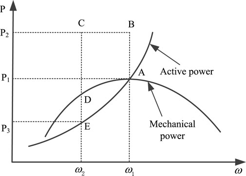
FIGURE 1. Operating curve of rotor kinetic energy control.
The mechanical power curve in Figure 1 illustrates the varying mechanical power of the wind turbine unit with rotational speed. The electromagnetic power curve shows the output active power corresponding to the rotational speed of the wind turbine, which refers to the electromagnetic power. In normal operation, the mechanical and electromagnetic power are equal, as shown in point A in Figure 1, when the wind turbine operates at maximum power output and the rotational speed is ω1. When the frequency of the system decreases, the frequency auxiliary control module of the wind turbine makes its electromagnetic power run from point A to point B, and the electromagnetic power increases from P1 to P2, responding to the change in system frequency. In the process of frequency regulation, the electromagnetic power remains constant from point B to point C. Meanwhile, the mechanical power gradually decreases from point A to point D and the rotational speed of the wind turbine increasingly declines from ω1 to ω2. The falling process of the rotor is the constant release of its kinetic energy, which is converted into active power output and supported by the inertia of the system. Constrained by the speed limit of the wind turbine, take ω2 as the lower limit of the wind turbine speed, at which time the wind turbine is forced to exit the frequency regulation mode; that is, the end of frequency regulation. Because the electromagnetic power is lower than the mechanical power after frequency regulation, the speed of the wind turbine will continue to decrease, which will activate the low-speed protection and cause the unit to shut down. Thus, the control of rotor speed recovery must occur after the regulation of the rotor kinetic energy. The electromagnetic power is reduced to power point E corresponding to the current speed; that is, the electromagnetic power is reduced from P2 to P3, the electromagnetic power is restored from point E to point A, and the mechanical power is restored from point D to point A to finally run at the initial point A. The essence of speed recovery control is that the mechanical power is always greater than the electromagnetic power, the wind turbine speed increases continuously from ω2 to ω1 to recover the initial speed, and the wind turbine again runs at its maximum output power. The aforementioned analysis considers a constant wind speed during regulation of the wind turbine frequency as this frequency regulation based on rotor kinetic energy occurs rapidly; thus, the potential wind speed fluctuation is not high.
Thus, control of the rotor kinetic energy does not issue active power to the system. In the context of energy conservation, the increased active power in the frequency regulation process is equal to the active power absorbed during the speed recovery, which cannot improve the steady state value of the system frequency stability. It mainly improves the maximum frequency offset and RoCoF index of the system, which play roles in rapid responses to frequency changes in the whole system. Improving the frequency response of the system can reduce the frequency maximum offset and prevent an excessive frequency drop that triggers the frequency protection action to cause the wind turbine to go off-grid and threaten the frequency stability of the system.
The frequency characteristics of the synchronous generator and load should be considered when controlling the frequency regulation of wind turbine rotor kinetic energy. The control block diagram is shown in Figure 2.
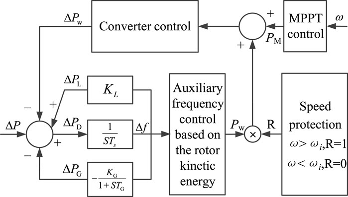
FIGURE 2. Schematic diagram of the rotor kinetic energy control.
Figure 2 considers the inertia and primary frequency regulation characteristics of synchronous generators, their load frequency response characteristics, and the additional frequency response characteristics of wind turbines. ΔPW is the wind turbine output power variation, ΔPL is the load absorbed power variation, ΔPG is the synchronous generator mechanical power variation, ΔP is the disturbance power, ΔPD is the system power imbalance, KL is the load frequency regulation benefit coefficient, Ts is the synchronous generator inertia time constant, KG is the synchronous generator frequency static characteristic coefficient, TG is the synchronous generator primary frequency regulation time constant, and the wind turbine speed protection module ωi is the minimum limit of the exit frequency regulation speed, which is jointly determined according to the operating conditions of the wind turbine and the minimum inertia demand of the power system, and will be analyzed in detail subsequently. To prevent the wind turbine from shutting down due to excessive participation in frequency regulation, when the rotational speed is lower than the minimum limit ωi, the enable signal R is set to 0 by the speed protection module, which makes the wind turbine exit the frequency regulation mode. The main aim of the present study was to determine the optimal frequency regulation strategy for wind turbines based on the flexibility and controllability of the output power of wind turbines. In Figure 2, the auxiliary frequency control is mainly used to determine the additional active power of the wind turbine at the beginning of frequency regulation, superimposed with the power value of the MPPT in normal operation into the converter control module to adjust the output power of the wind turbine to achieve primary frequency regulation. The detailed frequency control process will be studied in detail in follow-up studies.
3 Modelling of the minimum inertia demand of the power system
The main indexes for evaluating the frequency response characteristics of the system include the maximum frequency dropout rate, the maximum frequency offset, and the steady-state frequency. Inertia control based on rotor kinetic energy can provide an energy source for electromagnetic power, which does not provide unbalanced power for the system but rather buffers the unbalanced power. However, it plays an important role in maintaining the balance of active power supply and demand, which can slow frequency fluctuations and provide time for the primary frequency regulation of the system. Thus, inertia control is an indispensable part of maintaining frequency stability and plays a role in resisting frequency changes.
The inertia of the system described in energy form can be expressed as:
where ESG represents the synchronous generator inertia, ENE represents the new energy virtual inertia, EIM represents the asynchronous motor inertia, and EL represents the static load equivalent inertia. Synchronous generators and loads can provide delay-free inertia support. The virtual inertia of new energy mainly includes two control modes, rotor kinetic energy control and virtual synchronous machine control. This study mainly focuses on rotor kinetic energy; however, there is a certain time delay in rotor kinetic energy control of approximately 100 ms (Morren et al., 2006). Due to slip, the initial inertia of the frequency fluctuation of the asynchronous motor is very small before the moment of inertia fully responds to the frequency change (Wang and Yuan, 2018). The schematic diagram of support power in the process of system inertia response is shown in Figure 3.
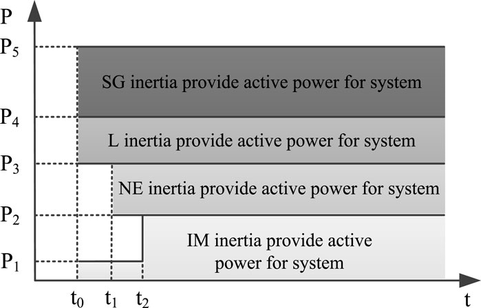
FIGURE 3. Output schematic of the system inertia.
The inertia constant of the system can be obtained from Eq. 1.
where S represents the system capacity.
Combined with Figure 2 and Eq. 2, the dynamic equation of system frequency can be obtained as follows:
where Hs represents the actual value and the remaining variables represent each unit.
This study evaluated the minimum inertia demand of the system based on the RoCoF and the maximum frequency offset to control the virtual inertia output of the wind turbine. Eq. 3 shows that system inertia, generator primary frequency regulation, load frequency characteristics, and wind turbine inertia are the main factors affecting the RoCoF and the maximum frequency offset. Next, the minimum inertia demands of the system are analyzed in two cases.
3.1 Minimum inertia based on RoCoF constraints
When a disturbance causes a system power imbalance, the system inertia is at a minimum, resulting in a maximum RoCoF. The RoCoF value at this time is used as a constraint to evaluate the system minimum inertia demand. The system frequency does not deviate due to the initial disturbance. Meanwhile, the synchronous generator and load cannot respond to the system frequency regulation effect. Eq. 3 shows that the frequency variation is only related to the system inertia and disturbance power, as follows:
From Eq. 4, the minimum inertia of the system under the RoCoF constraint is:
In Eq. 5, the influence of the inductive load should also be considered at the moment of a power disturbance. Therefore, the disturbance power in Eq. 5 should be modified and the static voltage equivalent inertia of inductive load should be removed, as follows:
In the aforementioned equation, ΔPU can be expressed as:
where U0 represents the initial voltage before disturbance, U represents the instantaneous voltage of disturbance, kz represents the proportionality coefficient of a constant impedance load, ki represents the proportionality coefficient of constant current load, and kp represents the proportionality coefficient of a constant power load.
Eq. 6 does not consider how the disturbance power ΔP occurs. In general, the tripping of large units or power differences in the contact line load cause power disturbances that affect the stability of the system frequency. Different disturbance types have different effects on the system inertia level. For example, a DC blocking fault generates a disturbance power ΔP but does not affect the inertia level of the whole system. However, a break in the AC line or a synchronous machine tripping accident will not only cause the system disturbance power ΔP but also reduce the system inertia and further worsen the system frequency. Therefore, the minimum inertia demand of the system at this time is:
where ΔHG represents the amount of inertia change caused by synchronous generator withdrawal or AC line shorting.
Regarding the RoCoF, China’s power grid has not made clear requirements, only clear provisions on the maximum frequency deviation. The equipment-level anti-islanding protection setting for distributed power supplies in the United Kingdom grid is 0.125 Hz/s; however, the blackout on August 9, 2019, caused nearly 350 MW of distributed power supplies to go off-grid because the system RoCoF exceeded this setting. Therefore, the RoCoF cannot be ignored with the gradual increase of the power electronic domination of the power system.
3.2 Minimum inertia based on frequency deviation constraints
To prevent blackouts caused by the disconnection due to low-frequency load shedding of systems experiencing power shortages, the lowest frequency of the system after the fault should not be lower than the first round value of the third line of defense line of low-frequency load shedding. The maximum offset of this frequency is used as a constraint to evaluate the minimum inertia demands of the system.
After the disturbance, the system frequency starts to deviate from the normal value. Initially, due to the small frequency shift and the dead zone of frequency regulation devices, no frequency regulation devices are operating and only the load is involved in the system frequency response. The primary frequency control of the wind turbine then starts to operate and the overall system imbalance is gradually reduced due to the faster frequency response of the wind turbine and the less durable frequency response capability of the rotor kinetic energy. Subsequently, the primary frequency regulation control of the thermal power unit begins to play a role. The system frequency will reach its limit when the output power of the primary frequency regulation control is equal to the initial unbalanced power. The frequency response of the system is divided into three processes. Therefore, the frequency response process of the system is simulated by piecewise linearization, as shown in Figure 4.
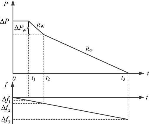
FIGURE 4. System frequency response process.
In Figure 4, t1 corresponds to Δf1, t2 corresponds to Δf2, and t3 corresponds to Δf3. t1 represents the time corresponding to the dead zone of the frequency response of the system frequency regulation device, t2 represents the time corresponding to the end of the frequency regulation of rotor kinetic energy control in the wind turbine, and t3 represents the time corresponding to the end of system frequency regulation, in which this regulation of the thermal power unit mainly bears the power shortage of the system. To facilitate the analysis, the system power needed for the recovery control of the wind turbine is also considered in this period. The frequency response of the system is involved in the entire process until the power shortage ΔP = 0. Δf3 is the maximum frequency offset, which is used to evaluate the minimum inertia demands of the system.
From the moment of fault occurrence 0 to the moment when the system frequency deviation reaches the extreme value t3, the integral solution of Eq. 3 is determined using the piecewise linearization method, as follows:
where ΔPL = KLΔf. Eq. 9 can then be expressed as:
In Eq. 10,
During the 0–t1 phase, all frequency regulation control devices are started and the active power imbalance ΔP of the system remains unchanged; that is:
During the t1–t2 phase, the control of the auxiliary frequency of the wind turbine rotor kinetic energy, meanwhile:
where RW represents the primary frequency regulation rate of wind turbine rotor kinetic energy, specifically expressed as:
During the t2–t3 phase, the primary frequency regulation of the thermal power unit is started; meanwhile:
where RS represents the primary frequency regulation rate of the thermal power units, specifically expressed as:
Since the power absorbed by the wind turbine recovery control is considered in phase t2–t3, the frequency regulation power provided by the generator is represented in the following equation:
The frequency setting value of the first round of low-frequency load shedding is 49 Hz (Sheng et al., 2021) according to the scheme for setting the low-frequency load shedding of the power system. Therefore, the Δf3 in this study was 1 Hz. Because the system is constrained by both the RoCoF and the maximum frequency offset, the minimum inertia of the system should be the maximum under the two constraints to ensure sufficient system inertia and improve the frequency stability of the system, as follows:
4 A strategy for the regulation of wind power auxiliary frequency based on the minimum inertia demand
The wind turbine provides inertial support for the system through releasable rotor kinetic energy. The wind turbine rotor kinetic energy equation is:
where HW represents the wind turbine inertia, ω represents the wind turbine rotor speed, PWe represents the wind turbine electromagnetic power, and PWm represents the wind turbine mechanical power.
In rotor kinetic energy control, the rotor speed of the wind turbine is constrained by the lower limit of the lowest speed. Therefore, the maximum inertia provided by the wind turbine is:
where EN represents the rotor kinetic energy corresponding to the rated speed ωN of the wind turbine, E0 represents the kinetic energy corresponding to the lower limit of rotor speed protection ω0, and PN represents the rated power of the wind turbine. Therefore, the inertia of any rotational speed ω between the rated speed ωN and the lower limit of speed protection ω0 is:
where Eω represents the kinetic energy corresponding to the rotor speed ω.
To quantitatively describe the inertia provided by the wind turbine to the system, the available inertia factor kH of the wind turbine is defined as:
In this study, taking ω0 = 0.7 ωN, Eq. 21 can be expressed as:
where ω∗ represents the per unit; when ω∗ is 1, kH = 1, and when ω∗ is 0.7, kH = 0, so that
The inertia provided by the rotor kinetic energy control of wind turbines aims to provide power support for the system. The output power is mainly restricted by the upper and lower limits of the converter power. In rotor kinetic energy control, the output electromagnetic power of the wind turbine is limited by the converter capacity. The specific constraint equation is:
Rotor kinetic energy control leads to changes in wind turbine speed and consequently, changes in wind turbine output mechanical power, that is, the power variation in Eq. 19 changes. Zhou and Lu (2011) reported that the relationship between the mechanical power output PWm and rotational speed of the wind turbines can be described as follows.
The output inertia of the wind turbine differs due to the varying working conditions of each wind turbine in the wind farm. The output inertia of the whole wind farm is:
where PNi represents the rated power of the ith wind turbine, kHi represents the available inertia factor of the ith wind turbine, and Hmaxi represents the maximum inertia of the ith wind turbine. Among them:
Increasing the primary frequency regulation rate of the frequency regulation device and reducing the adjustment time can reduce the inertia demand of the system to improve the primary frequency regulation of the system. For thermal power units, the frequency regulation rate is constrained by the unit’s own physical characteristics and stability; therefore, it is usually relatively fixed and cannot be improved. Advanced communication technology and active control based on fault drive can be used to shorten the adjustment time (Li et al., 2018) and improve the frequency response ability of the system.
In the primary frequency regulation of wind turbine based on converter control output power, whose control parameters are not subject to physical constraints, the output power can be designed according to the actual needs of the system and can quickly respond to the active power of the system frequency output, which can be equivalent to increasing the frequency regulation rate and reducing the adjustment time. Control based on rotor kinetic energy can reduce the minimum inertia demand of the system and improve the frequency regulation ability of the system. Rotor kinetic energy control aims to reduce the minimum inertia demand of the system. The specific objective function is:
According to the mathematical model established previously, including the dynamic equal constraint equation Eq. 27 and the unequal constraint equation Eq. 24, the output power of the wind farm is solved according to the objective function constructed by Eq. 28, and the system actively participates in primary frequency regulation.
The system will exit the frequency regulation mode and enter the speed recovery phase when the wind turbine speed reaches the lower limit. As shown in Figure 1, the prevention of accidental secondary drops in frequency requires a comprehensive consideration of the regulation moment of wind turbine exit frequency and frequency regulation power, as well as cooperation with the primary frequency regulation of the thermal power unit to allow the wind turbine to smoothly exit frequency regulation and restore the speed to the state before the frequency regulation. The output power process of the wind turbine is shown in Figure 5.
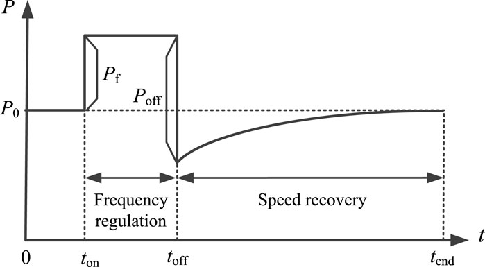
FIGURE 5. Exit of the wind turbine from the frequency regulation process.
In Figure 5, ton represents the starting moment of the regulation of wind turbine frequency; toff represents the moment of wind turbine withdrawal from frequency regulation; tend represents the ending moment of the control of wind turbine speed recovery; P0 represents the initial power value of the wind turbine; Pf represents the frequency regulation power; and Poff represents the exit frequency regulation power.
In the process of speed recovery, the change of rotor speed is still determined by the motion equation of the wind turbine rotor. The integration of both sides of Eq. 19 provides the output power Pe(t) of the control for the recovery of wind turbine rotor speed.
This study proposed the use of the piecewise linearization method to obtain an approximate solution based on the complexity of the aforementioned integral solution. Assuming that a segment of linearization is used to describe the output power, the output power is expressed as:
where kp represents the output power coefficient as follows:
where ωoff represents the speed of the wind turbine when exiting frequency regulation.
Among them,
Among them:
Using the same method, the multi-stage linearized output power curve can be obtained and the speed recovery control of the wind turbine can be achieved. The control of the speed recovery mainly depends on the exit frequency regulation time toff, the frequency regulation power Pf, and the exit frequency regulation power Poff, while Pf and Poff are determined by the real-time inertia of the wind turbine.
Meanwhile, ensuring the normal operation of wind turbine speed recovery requires setting the speed change rate as follows:
Combined with the frequency regulation characteristics of the thermal power unit and load, according to the established equation for the auxiliary frequency regulation of the wind turbine, the optimization model is solved according to the optimization objective function. This study applied improved GA (Yang et al., 2019) to obtain the optimal output frequency regulation power of the wind turbine from the aforementioned model. Given the large-scale wind farm cluster participating in the system frequency regulation, this study proposed a control scheme based on inertia demand, as shown in Figure 6.
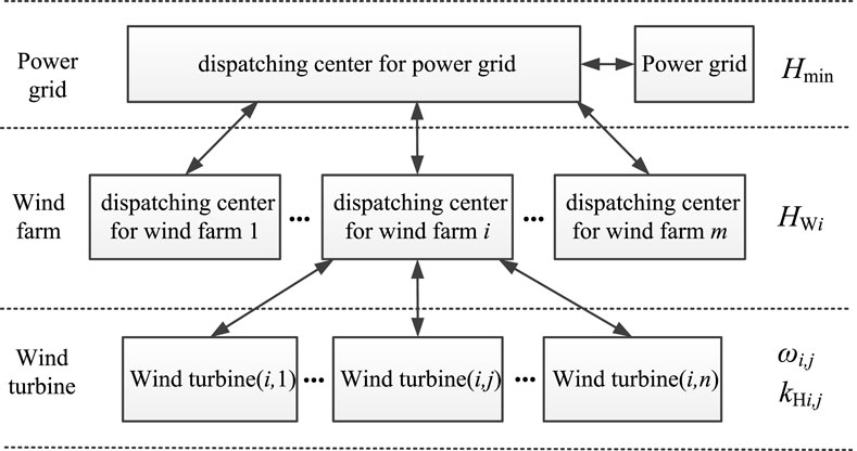
FIGURE 6. Structure diagram of the inertia control principle for wind farms.
5 Example analysis
This study used a typical IEEE two-area four-machine system as an example for the simulation calculations. The original system structure was modified considering the access of large-scale wind turbines. The wiring schematic is shown in Figure 7, with specific parameters as described by Kundur (2002).
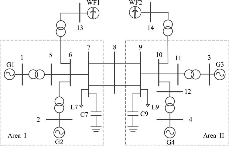
FIGURE 7. Wiring diagram of the simulation.
As shown in Figure 7, the simulation system included four synchronous generators and two wind farms. The wind farms both comprised 200 units of 1.5 MW doubly-fed wind turbines, with a total capacity of 600 MW each. In normal operation, the load of the system was 2200 MW, with an adjustment coefficient kL = 2%. The rated power, inertia time constant, and node type of the synchronous generator are shown in Table 1.
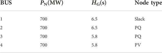
TABLE 1. Parameters of a synchronous generator.
To maximize the consumption of new energy, all wind turbines in the wind farm use maximum power point tracking (MPPT) control. Due to the use of rotor kinetic energy control, inertia control is performed according to the rotor speed. The output inertia of the wind turbine is evaluated in real-time based on the rotor speed. As wind turbines have short-term overload capability, this study proposed that rotor kinetic energy control is not affected by the wind speed; rather it is only determined by the rated and overload capacities of the converter.
To fully analyze the process and mechanism of the rotor kinetic energy control of the wind farm participating in the primary frequency regulation of the system, the wind power over 24 h was used to analyze the output inertia control and primary frequency regulation. To demonstrate the feasibility and effectiveness of the rotor kinetic energy control, the data of wind farms operating at low wind speed were selected from two large wind farms in the Baotou area of the Inner Mongolia Autonomous Region. The output power of the wind turbine reached the rated power when the wind turbine was operating above the rated wind speed working condition. Meanwhile, the wind turbine cannot participate in the system frequency regulation through the rotor kinetic energy control. In general, this system relied on power reserve control or the energy storage configuration to participate in the regulation of the system frequency. Thus, rotor kinetic energy control is only applicable to wind turbine output power below the rated power conditions. Therefore, this study mainly assessed the optimal power control of output frequency regulation and rotor speed recovery with the control of rotor kinetic energy participating in the regulation of the system frequency under the rated wind speed. Future studies are needed to assess the participation of wind turbines at full wind speed in the system of primary frequency regulation. The 24-h unit output and load power of the system are shown in Figure 8.
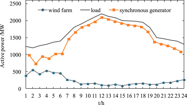
FIGURE 8. Unit output and load power for each 24 h period.
To verify the effectiveness of the method proposed in this study, the dynamic energy control of the wind turbine rotor was first simulated and analyzed. The operating conditions of the wind turbine in period 1 were selected, in which the disturbance setting was a sudden load power of 150 MW, the constraint value of maximum frequency offset was 1 Hz, and the constraint value of RoCoF was 2 Hz/s. The output electromagnetic power and mechanical power of the wind turbine during primary frequency regulation based on rotor kinetic energy control are shown in Figure 9 The rotor speed is shown in Figure 10.
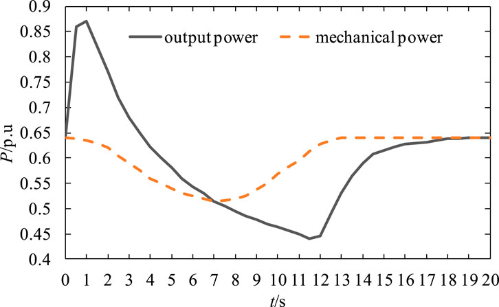
FIGURE 9. Mechanical and electromagnetic power of the wind turbine frequency regulation process.
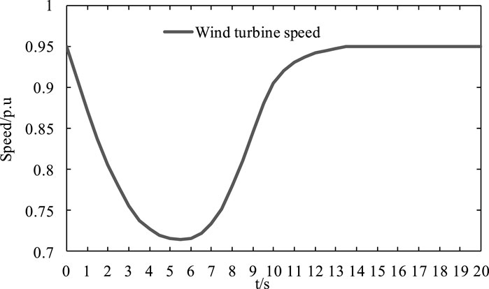
FIGURE 10. Wind turbine speed.
Figure 9 shows that, after the wind turbine auxiliary frequency control system detects a frequency fluctuation, it quickly releases the rotor kinetic energy to provide output power to support the decline of the system frequency. This stage mainly depends on the inertia output of the wind turbine to improve the system’s capability for frequency response. As the inertia output of wind turbines is not long-lasting, the maximum power output decreases gradually after 1.5 s and recovers gradually after reaching the lowest point. This process is coordinated with the frequency regulation control of the thermal power units, which provides optimal control of the frequency response of the system.
Figure 10 shows that the wind turbine speed decreases gradually under the control of the rotor kinetic energy. Due to restriction by the speed limit of the wind turbine, the speed no longer decreases at about 5.5 s. At this time, the rotor kinetic energy has been fully released and the rotor speed enters the recovery control stage until reaching the initial state.
The frequency variation of the system under the control of the rotor kinetic energy of the wind turbine is shown in Figure 11.
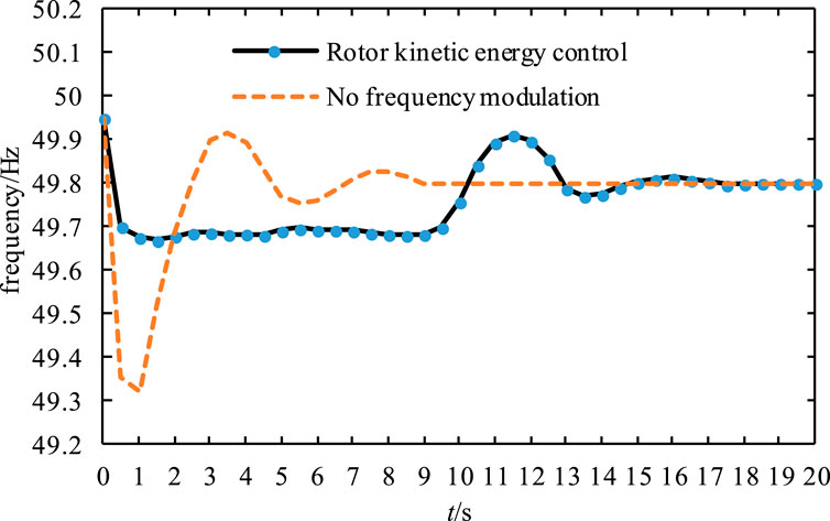
FIGURE 11. System frequency change.
Figure 11 shows the significantly improved RoCoF and maximum frequency offset under the effect of rotor kinetic energy control of the wind turbine, especially the maximum frequency offset. The maximum frequency offset
The frequency response capability of the system under conditions of power shortage is analyzed based on the power distributions in 24-h periods shown in Figure 8. At this time, the disturbance mode is set to power shortage, which is 10% of the total load. The 24 h available inertia of the two wind farms is shown in Table 2.
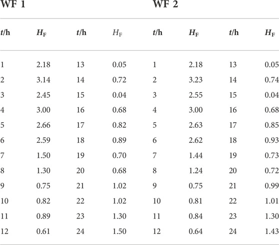
TABLE 2. Output inertia constant of the wind farm.
Table 2 illustrates the varying working conditions of wind turbines in different periods, which result in large differences in the output inertia of the wind turbines, which lead to different frequency response capabilities of the system. For example, during periods 13 and 15, the output inertia of the wind turbine is almost 0. The main reason is that the output and rotor speed of the wind turbine in the wind farm are small; thus, it cannot provide excess inertia output to participate in the frequency regulation of the system.
The minimum inertia demand Hmin and the actual inertia output Hs of the simulation example can be obtained according to Table 2 and the system minimum inertia demand calculation equation, as shown in Figure 12.
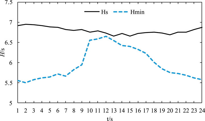
FIGURE 12. System frequency change.
Figure 12 shows the changes in the power shortage of the system over 24 h, which lead to greatly varying minimum inertia demands of the system. However, the real-time output inertia of the system does not change much and the available output inertia is larger than the minimum inertia demand of the system. This also shows that the stable operation of the frequency of the system can be ensured under the constraints of maximum frequency offset and RoCoF.
The minimum system frequency and RoCoF under a 10% power shortage of the total load in 24 h in the simulated system are shown in Figure 13.
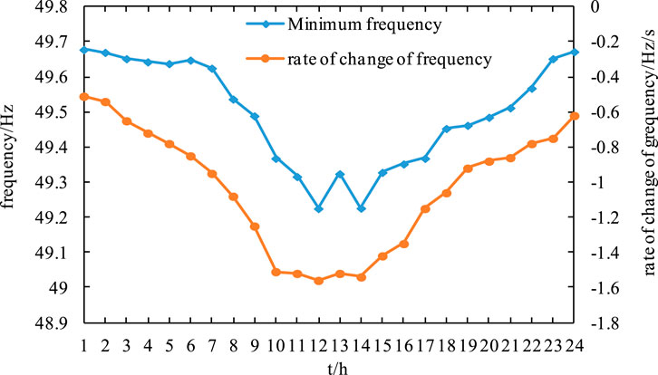
FIGURE 13. System frequency minimum and change rate.
Comparison of Figure 12 to Figure 13 shows that the frequency offset of the system and the absolute value of the RoCoF peak when the output inertia of the system is close to the minimum inertia demand of the system. If t = 12 h, the lowest value of the system frequency fmin = 49.225 Hz and the RoCoF fRCF = −1.56 Hz/s. This illustrates a weakened frequency response of the system in the case of insufficient system inertia, which is not conducive to the stable frequency operation of the system. Figure 13 shows that the minimum system frequency is basically in line with the trend of the system RoCoF, which also further illustrates a larger drop in system frequency when the RoCoF is larger. When the system power shortage is large, there is a lack of system inertia, which affects the frequency stability of the system. When the wind power permeability is large, to improve the inertia level of the system, rotor kinetic energy control should be considered to coordinate control with energy storage and other equipment with inertia support to improve the inertia output and frequency response of the system.
6 Conclusion
Considering the advantages of wind turbine rotor kinetic energy control, including rapid response and robust plasticity, in frequency regulation, this study proposes the use of an optimal rotor kinetic energy control considering the lowest system frequency value and the RoCoF constraint system. The system frequency response capability is improved by quickly providing inertia support to actively respond to system frequency fluctuations. The main conclusions obtained from the study were as follows.
1) The frequency regulation of wind turbine rotor kinetic energy control considers the frequency characteristics of synchronous generator and load to construct the system frequency regulation scheme based on inertia demand. The calculation model of system minimum inertia demand based on the lowest frequency and the constraint of system RoCoF is obtained. The optimal control scheme for primary frequency regulation for rotor kinetic energy control of wind turbines was established based on the minimum inertia demand of the system.
2) The optimal control strategy for rotor kinetic energy can allow the smooth control of electromagnetic and mechanical power in the process of wind turbine frequency regulation and rotor speed recovery, which can effectively avoid the problem of secondary frequency drop in the traditional rotor kinetic energy control. Meanwhile, control of rotor kinetic energy improves the lowest frequency of the system and also reduces the absolute value of RoCoF. The control of the wind turbine rotor kinetic energy provides inertia support for the system, which benefits the frequency stability of the whole system. Therefore, increasing the output inertia of the system is an effective way to address the frequency stability of power systems with high proportions of new energy.
Data availability statement
The raw data supporting the conclusion of this article will be made available by the authors without undue reservation.
Author contributions
LS: conceptualization, research strategy, and writing—original draft preparation. PY: writing—original draft. HJ: translation and validation. YX: research strategy. LK: data curation. XL: assisting other authors.
Funding
This work was jointly supported by Key laboratory open subject of the Ministry of Education (MPSS2021-02), Inner Mongolia Autonomous Natural Science Foundation Project(2021MS05060), and Inner Mongolia Autonomous region Major Project (2021ZD0029).
Conflict of interest
The authors declare that the research was conducted in the absence of any commercial or financial relationships that could be construed as a potential conflict of interest.
Publisher’s note
All claims expressed in this article are solely those of the authors and do not necessarily represent those of their affiliated organizations, or those of the publisher, the editors, and the reviewers. Any product that may be evaluated in this article, or claim that may be made by its manufacturer, is not guaranteed or endorsed by the publisher.
References
Arani, M. F. M., and Mohamed, A. R. I. (2018). Dynamic droop control for wind turbines participating in primary frequency regulation in microgrids [J]. IEEE Trans. Smart Grid 9 (6), 5742. doi:10.1109/TSG.2017.2696339
Attya, A. B. T., and Hartkopf, T. (2013). Control and quantification of kinetic energy released by wind farms during power system frequency drops. IET Renew. Power Gener. 7 (3), 210–224. doi:10.1049/iet-rpg.2012.0163
Cao, X., Stephen, B., Abdulhadi, I. F., Booth, C. D., and Burt, G. M. (2016). Switching markov Gaussian models for dynamic power system inertia estimation. IEEE Trans. Power Syst. 31 (5), 3394–3403. doi:10.1109/tpwrs.2015.2501458
Fang, Y. (2019). Reflections on frequency stability control technology based on the blackout event of 9 August 2019 in UK [J]. Automation Electr. Power Syst. 43 (24), 1. doi:10.7500/AEPS20191011006
Gu, H., Yan, R., and Saha, T. K. (2018). Minimum synchronous inertia requirement of renewable power systems. IEEE Trans. Power Syst. 33 (2), 1533–1543. doi:10.1109/tpwrs.2017.2720621
Johnson, S. C., Papageorgiou, D. J., Mallapragada, D. S., Deetjen, T. A., Rhodes, J. D., Webber, M. E., et al. (2019). Evaluating rotational inertia as a component of grid reliability with high penetrations of variable renewable energy. Energy 180, 258–271. doi:10.1016/j.energy.2019.04.216
Ke, X., Zhang, W., and Li, P. (2020). Fuzzy adaptive virtual inertia control for high wind power penetration system[J]. Power Syst. Technol. 44 (6), 2121. doi:10.13335/j.1000-3673.pst.2019.1349
Kundur, P. (2002). Power system stability and control. trans. Beijing: Book Translation GroupChina Electric Power Press.
Lee, J., Muljadi, E., Srensen, P., and Kang, Y. C. (2016). Releasable kinetic energy-based inertial control of a DFIG wind power plant. IEEE Trans. Sustain. Energy 7 (1), 279–288. doi:10.1109/tste.2015.2493165
Li, S., Wang, W., and Zhang, X. (2019). Impact of wind power on power system frequency and combined virtual inertia control[J]. Automation Electr. Power Syst. 43 (15), 64. doi:10.7500/AEPS20190103005
Li, W., Jin, C., and Wen, K. (2018). Active frequency response control under high-power loss[J]. Automation Electr. Power Syst. 42 (08), 22. doi:10.7500/AEPS20170930010
Liao, K., Xu, Y., Yin, M. H., and Chen, Z. (2020). A virtual filter approach for wind energy conversion systems for mitigating power system frequency fluctuations. IEEE Trans. Sustain. Energy 11 (3), 1268–1277. doi:10.1109/tste.2019.2922302
Liu, J., Qi, Y., and Liu, Y. (2017). Wind farm primary frequency control strategy based on wind & thermal power joint control[J]. Proc. CSEE 37 (12), 3462. doi:10.13334/j.0258-8013.pcsee.161663
Morren, J., Pierik, J., and De Haan, S. W. H. (2006). Inertial response of variable speed wind turbines. Electr. Power Syst. Res. 76 (11), 980–987. doi:10.1016/j.epsr.2005.12.002
Moutis, P., Stavros, A., and NikosD, P. (2012). Improved load-frequency control contribution of variable speed variable pitch wind generators. Renew. Energy 48 (6), 514–523. doi:10.1016/j.renene.2012.05.021
Sheng, S., Fan, M., and Zhang, W. (2021). Optimization method of under frequency load shedding for high new energy proportion system[J]. Acta. Energiae. Solaris Sin. 42 (2), 365. doi:10.19912/j.0254-0096.tynxb.2018-0978
Thakallapelli, A., Nair, A. R., Biswas, B. D., and Kamalasadan, S. (2020). Frequency regulation and control of grid-connected wind farms based on online reduced-order modeling and adaptive control. IEEE Trans. Ind. Appl. 56 (2), 1980–1989. doi:10.1109/tia.2020.2965507
Tian, X. S., Wang, W. S., Chi, Y. N., Li, Y., and Liu, C. (2018). Virtual inertia optimisation control of DFIG and assessment of equivalent inertia time constant of power grid. IET Renew. Power Gener. 12 (15), 1733–1740. doi:10.1049/iet-rpg.2018.5063
Vidyanandan, K. V., and Senroy, N. (2013). Primary frequency regulation by deloaded wind turbines using variable droop. IEEE Trans. Power Syst. 28 (2), 837–846. doi:10.1109/tpwrs.2012.2208233
Wang, D., and Yuan, X. (2018). Available inertia estimation of induction machine in electromechanical timescale and its effects on frequency dynamics of power systems with renewable energy[J]. Proc. CSEE 38 (24), 7258. doi:10.13334/j.0258-8013.pcsee.172705
Xu, G., Liu, F., Hu, J., and Bi, T. (2018). Coordination of wind turbines and synchronous generators for system frequency control. Renew. Energy 129, 225–236. doi:10.1016/j.renene.2018.05.104
Yang, P., Li, Y., Liu, L., Dong, X., and Zhang, J. (2019). Optimal placement of grounding small resistance in neutral point for restraining voltage fluctuation in power grid caused by geomagnetic storm. IET Gener. Transm. Distrib. 13 (8), 1456–1465. doi:10.1049/iet-gtd.2018.6310
Zeng, H., Sun, F., and Li, T. (2017). Analysis of“9·28”blackout in Australia and its enlightenment to China[J]. Automation Electr. Power Syst. 41 (13), 1. doi:10.7500/AEPS20170120002
Zhang, G., Yang, J., and Sun, F. (2017). Primary frequency regulation strategy of DFIG based on virtual inertia and frequency droop control[J]. Trans. CHINA Electrotech. Soc. 32 (22), 225. doi:10.19595/j.cnki.1000-6753.tces.l70681
Zhao, J., Min, L., and He, X. (2019). Coordinated control strategy of wind power and energy storage in frequency regulation based on torque limit control[J]. Trans. China Electrotech. Soc. 34 (23), 4982
Zhou, Q., and Lu, Z. (2011). Wind power generation and power system[M]. Beijing: China Electric Power Press, 15.
Keywords: primary frequency regulation, rotor kinetic energy control, inertia response, speed control, wind turbine
Citation: Sun L, Yang P, Jiang H, Xu Y, Kang L and Lu X (2023) Research on primary frequency regulation strategies for ancillary wind power inertia based on the rotor kinetic energy. Front. Energy Res. 10:969549. doi: 10.3389/fenrg.2022.969549
Received: 15 June 2022; Accepted: 14 September 2022;
Published: 05 January 2023.
Edited by:
Marianne Rodgers, Wind Energy Institute of Canada, CanadaReviewed by:
Ola Carlson, Chalmers University of Technology, SwedenLinfei Yin, Guangxi University, China
Copyright © 2023 Sun, Yang, Jiang, Xu, Kang and Lu. This is an open-access article distributed under the terms of the Creative Commons Attribution License (CC BY). The use, distribution or reproduction in other forums is permitted, provided the original author(s) and the copyright owner(s) are credited and that the original publication in this journal is cited, in accordance with accepted academic practice. No use, distribution or reproduction is permitted which does not comply with these terms.
*Correspondence: Peihong Yang, yph_1025@126.com