 Dai Liu
 Xiao Han
 Long Liu
 Xiuzhen Ma
94% of researchers rate our articles as excellent or good
Learn more about the work of our research integrity team to safeguard the quality of each article we publish.
Find out more
ORIGINAL RESEARCH article
Front. Energy Res. , 17 August 2022
Sec. Advanced Clean Fuel Technologies
Volume 10 - 2022 | https://doi.org/10.3389/fenrg.2022.969525
This article is part of the Research Topic Advanced Technologies in Flow Dynamics and Combustion in Propulsion and Power,Volume II View all 15 articles
The increasing demand of digital twin marine engine requires real-time physical models for prediction. In two-stroke uniflow scavenging marine engines, a real-time physical model for the scavenging process is rarely found since it is difficult to describe the complex in-cylinder air motion. Without an accurate prediction of the fresh air loss and residual burned gas in the cylinder, the precision of combustion and emission simulation cannot be guaranteed as well. In a marine engine digital twin system, the scavenging ratio and fresh air skip are the vital for the further simulation of combustion and emission. To predict them in real-time, a novel zero-dimensional (0D) multi-stage scavenging model is proposed in this article. In the cylinder zone, the complex gas motion is ideally divided to four stages: exhaust gas blowdown, perfect displacement, displacement-mixing, and perfect mixing. The duration of each stage is determined by the engine design and control parameters. Then, the thermodynamic conditions at each stage are simulated to obtain the mass of residual burned gas, fresh air inlet, and outlet. The results of the 0D model agree well with the results of the CFD simulation, and the mean relative errors of temperature, pressure, and total mass do not exceed 3%, 4%, and 2%, respectively, which indicates the potential for the two-stroke marine engine digital twin system. It could also be applied in a control-oriental engine model or engine diagnostics in the future.
Large bore two-stroke engines are the main power units for vessels. With the critical challenges of emission and energy regulations, an efficient combustion strategy and low/zero carbon fuels have become the main approaches to improve engine efficiency and reduce emissions. Deng et al. (2018) explored the possibility and limitations of lean burn from the aspect of exhaust emissions Liu et al. developed a flexible spray model (Liu et al. 2022) and optimized the stochastic combustion model (Liu et al. 2022) to cope with the emissions issues and optimize the combustion. Zheng et al. (2018) developed a thermodynamic model to analyze the effects of different turbocharging parameters on engine boost pressure and pumping loss qualitatively. Furthermore, with the significant increase in engine complexity, simulation is increasingly becoming an important tool to support an engine’s full life cycle development. Luo et al. (2022) set up a three-dimensional (3D) model of a HPDI natural gas two-stroke marine engine, where the influence of geometry parameters on mixture flow, combustion, and emissions were presented and discussed. Liu et al. (2019) investigated the effects of injection strategies of dual fuels on combustion characteristics and emissions by the CFD simulation. In the course of study, it is found that the scavenging process affects the global engine performance in a two-stroke engine (Tomislav et al., 2022), and it should be properly designed and controlled for different fuels. Recently, based on traditional modeling and simulation, the digital twin technology has become a high-level sublimation of modeling and simulation technology and will further boost the development of engines (Liu et al., 2021), including the scavenging process of marine engines. In the digital twin system, models with different dimensions would be established for a geometrical design (Zhou et al., 2021) or a real-time performance investigation (Bondarenko and Fukuda., 2020). In most of digital twin applications, such as power systems, real-time models play a vital role in engine optimization, control, and diagnostics (Jiang et al., 2022). To develop reliable real-time engine models, researchers investigated different approaches, such as the 0D/QD model (developed by simplified physical, semi-physical, or empirical equations) and the data-driven model (developed by a machine-learning algorithm). The data-driven model (Wang et al., 2020) requires a large amount of data for training and verification, which has been widely applied in vehicle engines. However, the applications of the data-driven model in marine engine research are limited due to the lack of experimental data, especially for the large bore low-speed marine diesel engines. Therefore, the 0D/QD model (time is the only independent variable) is a good choice for the marine engine digital twin system in the current status.
Many researchers developed a quasi-model for combustion in two-stroke marine engines (Ji et al., 2016; Liu et al., 2020). However, there are rare literature studies to describe the uniflow scavenging process in a marine two-stroke engine, due to its complex mixing of fresh air and exhaust gas in the cylinder. The control of fresh air escaping to the exhaust and residual exhaust gas in the cylinder is influenced by many design and control parameters, such as scavenge port geometry and exhaust valve lift. The complex gas motion would further affect the formation of the air/fuel mixture, flame propagation, combustion quality, pollutant formation, exhaust temperature, and so on. Thus, it is important to develop a scavenging model with high accuracy and real-time performance for the forecast of combustion and emission in future digital twin systems.
An ideal scavenging model includes perfect displacement, perfect mixing, and short-circuiting, but the real scavenging process is normally a combination of them in different stages and zones, which can be observed in many CFD (Andersen et al., 2014; Wang et al., 2016) and experimental research studies (Ma et al., 2021). Therefore, a 0D scavenging model could be a combination of these sub-processes, either by a multi-stage (the scavenging process is divided in different stages based on the engine events) or multi-zone (cylinder is divided in different zones during the scavenging process) approach. Each stage or zone can be assumed as a displacement, mixing, or short-circuiting process. Foteinos and Papazoglou (Foteinos et al., 2019) updated the three-zone scavenging model, originally presented in (Kyrtatos and Koumbarelis, 1988) and applicable to two-stroke uniflow scavenged marine diesel engines, proposed a semi-empirical zero-dimensional three-zone model for a two-stroke uniflow-scavenged diesel engine based on the results of CFD simulations: the pure air zone, mixing zone, and pure exhaust gas zone. However, the multi-zone model introduced many calibration parameters for each zone’s mass transformation. Since a 0D scavenging model is aiming to simulate the in-cylinder residual exhaust gas and fresh air to the exhaust pipe for further combustion and performance simulation, the detailed in-cylinder mass exchange process is not necessary. And the multi-stage model, which could simulate the thermodynamic conditions before combustion, is sufficient for a real-time model application. To avoid the inaccuracy of thermal homogeneity of the incoming and exiting gases, Bajwa (Bajwa and Patterson, 2019) proposed a single-zone multi-stage model for a cross-scavenged engine, but its design and control parameters are different from those of the uniflow scavenging process.
To develop a real-time model for the design and control of the uniflow-scavenging process in a two-stroke marine engine digital twin system, a zero-dimensional multi-stage scavenging model is proposed in this article. The stages are determined by the scavenging ports and the exhaust valve’s opening and closing timings. The mass of fresh air/burned gas, temperature, and pressure in the cylinder are simulated in each stage accurately, and can also be derived from the intake pressure and exhaust valve opening and closing timings on the impact of the scavenging process law. Based on the fresh air and burned gas-mixing process from the CFD simulation, a novel displacement–mixing (simultaneous) sub-stage was proposed to predict the mixing conditions and combined with other stages determined by the scavenging ports and exhaust valve’s opening and closing timings. The mass of fresh air/burned gas, temperature, and pressure in the cylinder are simulated in each stage accurately, which are the key influential factors for the spray and combustion in the two-stroke engine digital twin system.
In the novel multi-stage model, the four stages are assumed: blowdown, perfect-displacement (PD), displacement-mixing (DM), and perfect-mixing (PM) in Figure 1. The blowdown stage begins with the exhaust valves opening (EVO) (A) and ends with the scavenging ports opening (SPO) (B), and the cylinder is occupied by residual exhaust gas. The PD stage is from point B to point C and the DM stage is from point C to point D, where the point C is used to adjust the ratio of PD and DM, and the cylinder is occupied by air and residuals or mixture one. The PD stage begins with the scavenging port closing (SPC) (D) and ends with the exhaust valve closing (EVC) (E), and there is only final mixture two in the cylinder at this stage. A summary of the key parameters of the ZDMS model is as shown in Table 1, where the orange indicates known quantities; the green indicates some key unknown quantities.
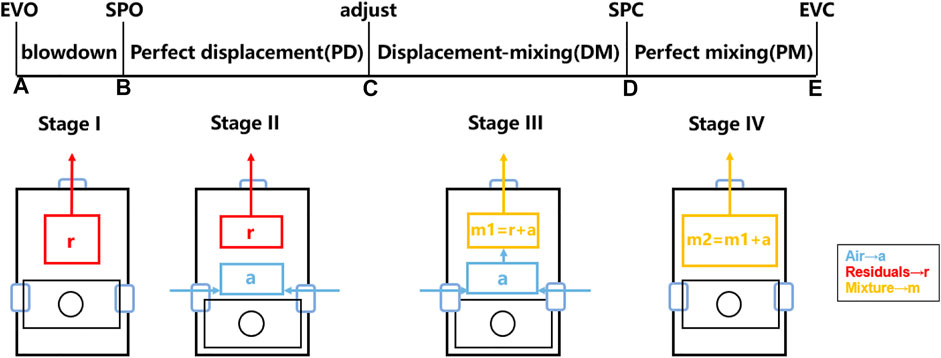
FIGURE 1. Schematic diagram of the zero-dimensional multi-stage model.
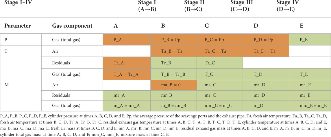
TABLE 1. Key parameters of the ZDMS model.
When the exhaust valve is opened, the in-cylinder pressure is normally higher than pressure in the exhaust pipe, which leads to the residuals flowing to the exhaust pipe as a blowdown process. Although the in-cylinder pressure might be lower than the pressure in the exhaust pipe, it is an unexpected situation in the scavenging process which would not be considered in the model. Therefore, the piston movement and loss of exhaust gas would lead to a sharp decrease in the pressure and temperature of the cylinder, where the pressure decreases from P_A to Pp, as shown in Figure 1. The discharge of exhaust gas during this process is regarded as an isentropic expansion process, the details are as follows.
The following are assumed during this stage:
• The isentropic index of all gases is constant.
• The wall of the cylinder is adiabatic.
• The gases in the cylinder are ideal, while gas constant is a constant value.
During this stage, the pressure of the residual exhaust gas and fresh air in the cylinder are assumed to be equal with an average manifold pressure, the temperature of the residual exhaust gas still remains from the results of the blowdown stage, and the temperature of the fresh air with
The following are assumed during this stage:
• The temperature and density of the fresh air in the cylinder are constant.
• The temperature of the exhaust gas is constant.
• The process occurs at a constant cylinder pressure.
• The entering fresh air pushes out the exhaust gas by a perfect displacement mechanism.
• There is no mass or heat that is allowed to cross the interface between the two gases.
• The wall of the cylinder is adiabatic.
The pressure of the residual exhaust gas and fresh air in the cylinder are still equal to the average manifold pressure. The temperature of fresh air remains the same as the scavenge port temperature, and the temperature of mixture one during the DM stage is consistent with the overall temperature at the end of the PD stage. The mass of the fresh air at the end of stage-III is the sum of the charged fresh air during this stage and the air in mixture one. The mass of the mixture decreases because of discharging through the exhaust valves, and final mass at this stage can be calculated by the following formulas.
where ma_CD represents the charging fresh air mass during the DM stage, and mm_a_D represents the mass of air in the mixture at time D.
The following are assumed during this stage:
• The temperature and density of the fresh air in the cylinder are constant.
• The temperature of the exhaust gas is constant.
• The process occurs at a constant cylinder pressure.
• The exhaust gas and fresh air from the last stage are mixed ideally and form a homogeneous mixture one.
• The ratio of fresh air and residual exhaust gas in mixture 1 remains the same as the original mixing ratio for this stage.
• The wall of the cylinder is adiabatic.
With the piston movement, the fresh air and mixture one from the last stage mix perfectly and formed homogenous mixture two. With the piston moving upward, the cylinder volume decreases and mixture two is discharged with the exhaust valve opening, so the temperature and pressure may increase or increase depending on the valve lift subsequently.
The following are assumed during this stage:
• Mixture one and fresh air from the last stage are mixed ideally and form a homogeneous mixture two.
• The whole cylinder is occupied by mixture 2.
• The wall of the cylinder is adiabatic.
Two-stroke engine experiments are costly and cannot obtain detailed fluid parameters of the scavenging process. Therefore, the corresponding CFD models validated by several cylinder pressure curves can be used to represent the engine and investigate the fluid characteristics with more operating conditions. Consequently, the real-time zero-dimensional model can be derived and finally applied to two-stroke marine engine digital twin systems. In this article, to confirm the accuracy of the ZDMS model, the corresponding CFD simulation model was carried out by CONVERGE. The simulation was based on a 6EX340EF marine low-speed diesel engine developed by China Shipbuilding Power Engineering Institute Co., Ltd. and the experimental data are also from the manufacturer. During the numerical simulation, the initial temperature and pressure of the scavenge port and exhaust pipe were obtained from experiments, while the cylinder mean temperature was derived from the measured cylinder pressure data. All the gases in the cylinder were marked as waste gas, the gases in the intake region were marked as fresh air, and the specific boundary conditions are described in Supplementary Appendix S1. Table 2 shows the engine specifications. Figure 2 shows the schematic diagram of the engine model structure.
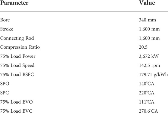
TABLE 2. 6EX340EF two-stroke engine specifications.
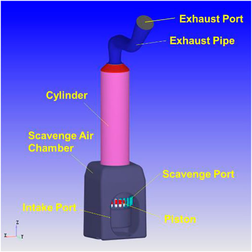
FIGURE 2. Schematic diagram of the 6EX340EF diesel engine model structure.
The CFD simulation adopts the RNG k-ε (renormalization group) turbulence model. Mesh quality will directly affect the computational results and computing time, so in this article, the mesh independence analysis was carried out. For the simulation of the scavenging process of the 6EX340EF diesel engine, the simulated base mesh was set as 4 cm, and the velocity and temperature-adaptive mesh refinement strategy (AMR) of 3–4 levels was adopted in the cylinder, and the fixed refinement strategy (FIX) of 1–3 levels was adopted in the whole cylinder, scavenge port, and exhaust valve. Based on the simulation results, three refinement strategies are added for a supplementary explanation. Table 3 below shows the number of meshes and computation time in the scavenging process under different refinement strategies. The mesh refinement strategy with a short computation time is selected under the condition of satisfying computation accuracy. Figure 3 shows the parameter variation under different mesh refinement strategies. In summary, it is most reasonable to select the refinement strategy with a 4 cm base mesh, three levels of AMR strategy, and three levels of FIX strategy for this scavenging process simulation.
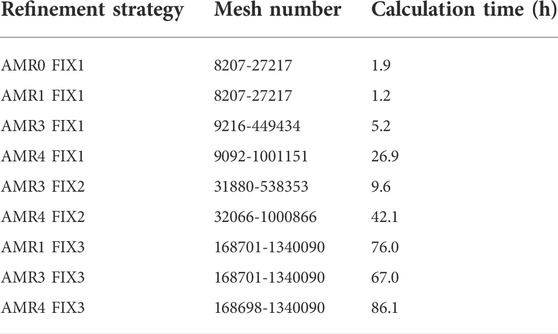
TABLE 3. Mesh number and calculation time statistics.
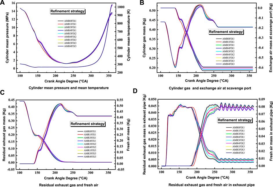
FIGURE 3. Variation of parameters such as (A) Cylinder mean pressure and mean temperature, (B) Cylinder gas and exchange air at scavenge port, (C) Residual exhaust gas and fresh air and (D) Residual exhaust gas and fresh air in exhaust pipe under different mesh refinement strategies.
The numerical simulation research ranges from 100°CA to 360°CA and the cylinder mean pressure in different conditions was compared with the experiment in Figure 4. Table 4 shows the relative deviation of simulation and experimental cylinder pressure at compression top dead center (TDC), and all the relative deviations were less than 0.1%, which illustrates the accuracy and reality of this CFD model.
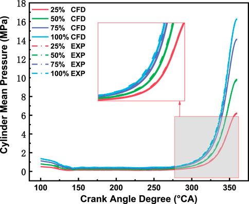
FIGURE 4. Comparison of the simulation and experimental cylinder pressures under different conditions.
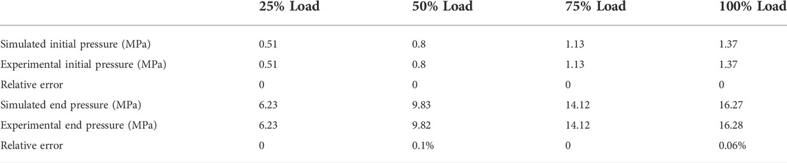
TABLE 4. Comparison of the simulation and experimental cylinder pressure relative deviations under different conditions.
The novel ZDMS model was compared against the results from the CFD simulations. The predicted fresh air mass, residuals mass, total gas mass, temperature, and pressure using the ZDMS were compared to the results predicted by the CFD model. The comparison results under 75% load are presented in Figure 5, where CFD results are presented with a solid line and the results of the ZDMS model are presented with a circle scatter.
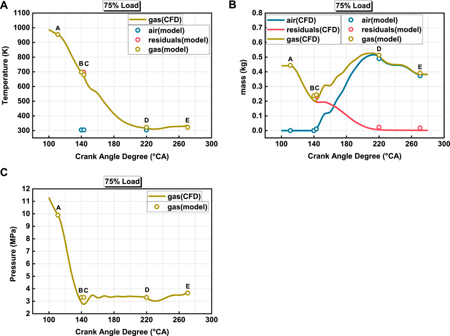
FIGURE 5. Evolution of (A) temperature, (B) mass and (C) pressure of each stage as predicted by the ZDMS model and the CFD model for the 75% load.
As Figure 5 shows, at the beginning of the scavenging process (A), there is only high temperature and pressure residual exhaust gas in the cylinder. During the blowdown stage, the exhaust gas is discharged continuously, and the temperature and pressure in the cylinder gradually decrease, which is also represented well in the ZDMS model (A→B). As the inlet port is opened and the increasing fresh air enters the cylinder after point B, the pressure in the cylinder fluctuates initially and becomes steady soon in the CFD model. This process is also represented in the ZDMS model from point B to C, where point C is used to adjust the ratio of the PD stage and the DM stage and it is found that a good calculation occurs when C is close to B. Then, with fresh air entering, the cylinder temperature decreases and the gas mass increases, which is consistent with the ZDMS model (C→D). After that, the exhaust valve is remains open, and with the discharging of mixture two, the cylinder temperature and pressure tends to decrease, but increases quickly caused by the piston moving up, here the ZDMS model is still in good agreement with the CFD results (D→E). It is worth proposing that the CFD simulation described the change process in detail, while the ZDMS model provided accurate stage conditions.
Furthermore, the ZDMS model under different conditions is verified by the CFD model. Table 5 shows the model input parameters for different loads, and Figure 6 shows the comparison results between the CFD model and the ZDMS model at 25%, 50%, and 100% load conditions with good agreement. In addition, another two-stroke engine was additionally selected and the comparative verification of the scavenging process was carried out. Table 6 and Table 7 show the engine specifications and parameters under different loads, respectively. As shown in Figure 7, the model still maintains a high agreement with the CFD results, which indicates the prediction ability in the scavenging process of the two-stroke uniflow scavenge engine.
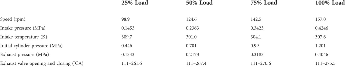
TABLE 5. Input parameter settings of the 6EX340EF engine under different loads.
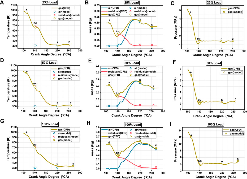
FIGURE 6. Comparison of the results of ZDMS model and CFD model for parameters such as (A) temperature, (B) mass and (C) pressure at 25% load, (D) temperature, (E) mass and (F) pressure at 50% load, and (G) temperature, (H) mass and (I) pressure at 100% load.
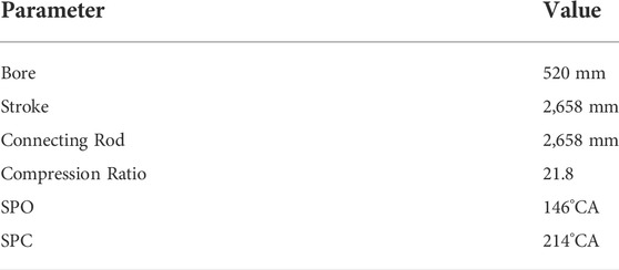
TABLE 6. RTX-8 engine specifications.
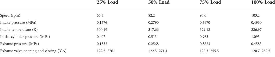
TABLE 7. Input parameter settings of the RTX-8 engine under different load conditions.
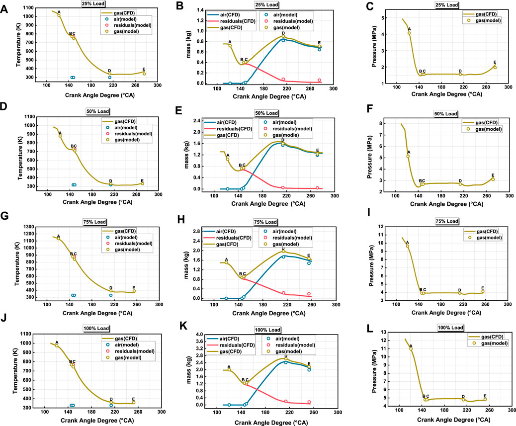
FIGURE 7. Comparison of the results of ZDMS model and CFD model for parameters such as (A) temperature, (B) mass and (C) pressure at 25% load, (D) temperature, (E) mass and (F) pressure at 50% load, (G) temperature, (H) mass and (I) pressure at 75% load, and (J) temperature, (K) mass and (L) pressure at 100% load.
To further investigate the scavenging process with the 0D model, charging efficiency (CE) and residual exhaust coefficient (REC), which are common evaluation indicators for the scavenging process, are proposed and calculated by the following formulas.
In this article, the effect of different intake pressures and exhaust valve opening and closing timings on the in-cylinder mass, CE and REC at the end of the scavenging process were investigated in the 6EX340EF engine at 75% load. Table 8 shows the settings of the relevant input parameters.
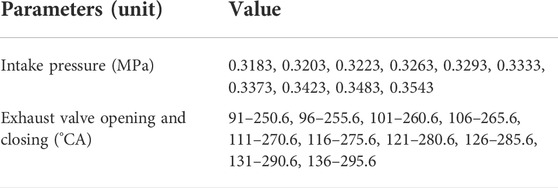
TABLE 8. Relevant input parameters under 75% load.
As shown in Figures 8A,B, the increase of the intake pressure results in the rise of the fresh air mass and CE with a decrease of residuals mass and REC. The change of them becomes negligible after the intake pressure increases to a certain value (around 0.34 MPa in this stage). A higher intake pressure could increase the mass of the fresh air in and out. As the mass of escaping fresh air increases (as shown in Figure 8C) with the growing intake pressure, the increased fresh air inlet cannot compensate the loss of fresh air. Therefore, the trapped air mass is only determined by the pressure of the inlet air, which is indicated by the CFD model and the 0D model in Figure 8.
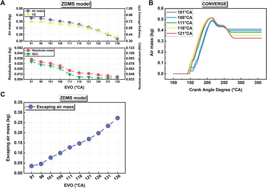
FIGURE 8. (A,B) Air mass, CE, residuals mass, REC, and (C) escaping air mass at 75% load with different intake pressures.
For the two-stroke uniflow scavenging engine, its scavenging process can be adjusted by the VVA system (Zhang et al., 2013). In this research, the exhaust valve opening duration is fixed at 159.6°, and the exhaust valve opening timing is gradually delayed from 91°CA to 136°CA. Figure 9 shows the normalized exhaust valve lift (EL) with different opening and closing timings.
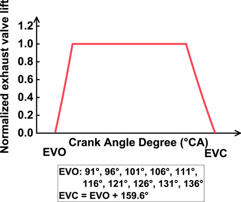
FIGURE 9. Opening profile of exhaust valves.
As Figure 10A shows, with the delay of the exhaust valve’s opening and closing timings, the air mass and CE decrease, due to the less residuals discharging during the blowdown stage which affects the final air mass trapped in the cylinder. As the PM stage becomes longer, more mixture two flows out of the cylinder, leading to the residual mass and REC decreases. Figure 10B shows that the predicted results of the ZDMS model are in good agreement with the CFD results. With the delay of the exhaust valve opening, the mass of the escaping air increases, which is shown in Figure 10C.
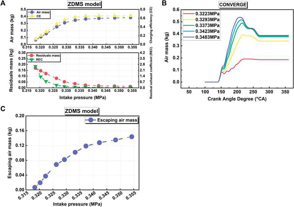
FIGURE 10. (A,B) Air mass, CE, residuals mass, REC, and (C) escaping air mass at 75% load with different EVOs.
In this article, a zero-dimensional multi-stage scavenging model is proposed to simulate the two-stroke engine’s uniflow scavenging process. The whole scavenging process is divided into four stages, in which the effects of different scavenging mechanisms are implicitly considered. In the model, the masses, temperature, and pressure of air and residual gas in different stages are predicted by a series of thermodynamic equations. Then, the results of the 0D model are compared with the CFD simulation results in two different engines, and a good agreement is found between the 0D and CFD models, which verifies the accuracy of the proposed model. Finally, the effects of the intake pressure and exhaust valve opening/closing timing on the scavenging process in the cylinder are also investigated, which indicates the same trend and influence in the CFD models. Therefore, the model is an accurate, efficient, and simple alternative to the complex CFD simulations if the details of the scavenging process are not considered. The model provides the initial conditions for subsequent combustion, which can be used as a scavenging process simulation module in the marine engine digital twin system.
The key elements of a digital twin system include the physical entity, the twin model, the twin data, and the dynamic interaction between them. The focus of the problems solved by the digital twin system varies in different stages of the whole life cycle of a marine engine, among which an accurate performance prediction is an important goal in the development of a digital twin system for marine engines during the performance verification part of the design phase and the test phase. The zero-dimensional multi-stage model proposed in this article better simulates the two-stroke engine scavenging process, and can be used as a part of the main mechanism model. By retaining data interfaces, the novel model can establish potential correlations with monitoring data such as environmental data, control data, and sensing data measured and processed from the marine engine entity to realize the dynamic interactions, and then coupling with other mechanism models to obtain a set of twin models closely related to the engine entity. As the core of the performance digital twin system, the twin model mainly focuses on the prediction of engine performance indexes such as power, economy, environment, etc.
The original contributions presented in the study are included in the article/Supplementary Material; further inquiries can be directed to the corresponding author.
DL: Writing and providing overall ideas; XH: Writing, data processing, and analysis; LL: Guiding the manuscript writing; XM: Supervision and funding.
This research is funded by Research of Controllable Combustion Technology in Marine Diesel Engine from National Key R&D Program of China, Ministry of Science and Technology (Grant No. 2017YFE0116400) and Marine Low-Speed Engine Project Phase I (Grant No. CDGC01-KT0102-001).
The authors declare that the research was conducted in the absence of any commercial or financial relationships that could be construed as a potential conflict of interest.
All claims expressed in this article are solely those of the authors and do not necessarily represent those of their affiliated organizations, or those of the publisher, the editors, and the reviewers. Any product that may be evaluated in this article, or claim that may be made by its manufacturer, is not guaranteed or endorsed by the publisher.
The Supplementary Material for this article can be found online at: https://www.frontiersin.org/articles/10.3389/fenrg.2022.969525/full#supplementary-material
Andersen, F. H., Hult, J., Nogenmyr, K. J., and Mayer, S. (2014). CFD analysis of the scavenging process in marine two-stroke diesel engines. Proceeding of the ASME 2014 Internal Combustion Engine Division Fall Technical Conference. October 2014, Columbus, Indiana, USA, ICEF 1, 1–13. doi:10.1115/icef2014-5438
Bajwa, A. U., and Patterson, M. (2019). A New single-zone multi-stage scavenging model for real-time emissions control in two-stroke engines. Proceeding of the ASME 2019 Internal Combustion Engine Division Fall Technical Conference. October 2019, Chicago, IL, USA, 20–23.
Bondarenko, O., and Fukuda, T. (2020). Development of a diesel engine’s digital twin for predicting propulsion system dynamics. Energy 196, 117126. doi:10.1016/j.energy.2020.117126
Deng, B. L., Li, Q., Chen, Y. Y., Li, M., Liu, A. D., Ran, J. Q., et al. (2018). The effect of air/fuel ratio on the CO and NOx emissions for a twin-spark motorcycle gasoline engine under wide range of operating. Energy 169, 1202–1213. doi:10.1016/j.energy.2018.12.113
Foteinos, M., Papazoglou, A., Kyrtatos, N., Stamatelos, A., Zogou, O., Stamatellou, A., et al. (2019). A three-zone scavenging model for large two-stroke uniflow marine engines using results from CFD scavenging simulations. Energies 12 (9), 1719. doi:10.3390/en12091719
Ji, C. W., Yang, J. X., Liu, X. L., Zhang, B., Wang, S. F., Gao, B. B., et al. (2016). A quasi-dimensional model for combustion performance prediction of an SI hydrogen-enriched methanol engine. Int. J. Hydrogen Energy 41 (39), 17676–17686. doi:10.1016/j.ijhydene.2016.07.146
Jiang, J. J., Li, H., Mao, Z. W., Liu, F. C., Zhang, J. J., Jiang, Z. N., et al. (2022). A digital twin auxiliary approach based on adaptive sparse attention network for diesel engine fault diagnosis. Sci. Rep. 12 (1), 675. doi:10.1038/s41598-021-04545-5
Kyrtatos, N. P., and Koumbarelis, I. (1988). A three-zone scavenging model for two-stroke uniflow engines. J. Eng. Gas. Turbine. Power 110 (3), 531–537. doi:10.1115/1.3240167
Liu, H. F., Li, J. R., Wang, J. T., Wu, C. H., Liu, B., Dong, J. J., et al. (2019). Effects of injection strategies on low-speed marine engines using the dual fuel of high-pressure direct-injection natural gas and diesel. Energy Sci. Eng. 7, 1994–2010. June. doi:10.1002/ese3.406
Liu, L., Peng, Y., Liu, D., Han, C. F., Zhao, N. B., Ma, X. Z., et al. (2020). A review of phenomenological spray penetration modeling for diesel engines with advanced injection strategy. Int. J. Spray Combust. Dyn. 12 (145), 175682772093406. doi:10.1177/1756827720934067
Liu, Y. Q., Li, X., Ren, W. C., and Sui, Y. F. (2021). Digital twin boosting leap-forward development of aero engine. Aerosp. Power 2021 (02), 24–29. (in Chinese).
Liu, L., Mei, Q. H., and Jia, W. N. (2022). A flexible diesel spray model for advanced injection strategy. Fuel 314 (145), 122784. doi:10.1016/j.fuel.2021.122784
Liu, L., Peng, Y., Huang, L., Han, C. F., and Ma, X. Z. (2022). Evaluation of impingement effects on high-power diesel engine mixing process with an optimized stochastic combustion model. Fuel 328 (145), 125239. doi:10.1016/j.fuel.2022.125239
Luo, W. F., Liu, H. F., Liu, L., Liu, D., Wang, H., and Yao, M. F. (2022). Effects of scavenging port angle and combustion chamber geometry on combustion and emmission of a high-pressure direct-injection natural gas marine engine. Int. J. Green Energy 00 (00), 1–13. doi:10.1080/15435075.2022.2079380
Ma, F. K., Yang, W., Wang, Y. F., Xu, J. F., and Li, Y. F. (2021). Experimental research on scavenging process of opposed-piston two-stroke gasoline engine based on tracer gas method. Int. J. Engine Res., 1–12. doi:10.1177/14680874211036613
Tomislav, S., Vedran, M., Vedran, M. V., and Igor, W. (2022). CFD analysis of a large marine engine scavenging process. Processes 10 (1), 141. doi:10.3390/PR10010141
Wang, X. Y., Ma, J., and Zhao, H. (2016). Evaluations of scavenge port designs for a boosted uniflow scavenged direct injection gasoline (BUSDIG) engine by 3D CFD simulations. SAE Technical Papers. doi:10.4271/2016-01-1049
Wang, B. W., Zhang, G. B., Wang, H. Z., Xuan, J., and Jiao, K. (2020). Multi-physics-resolved digital twin of proton exchange membrane fuel cells with a data-driven surrogate model. Energy AI 1, 100004. doi:10.1016/j.egyai.2020.100004
Zhang, Y., Zhao, H., Ojapah, M., and Cairns, A. (2013). CAI combustion of gasoline and its mixture with ethanol in a 2-stroke poppet valve DI gasoline engine. Fuel 109, 661–668. doi:10.1016/j.fuel.2013.03.002
Zheng, Z. Q., Feng, H., Mao, B., Liu, H. F., and Yao, M. F. (2018). A theoretical and experimental study on the effects of parameters of two-stage turbocharging system on performance of a heavy-duty diesel engine. Appl. Therm. Eng. 129, 822–832. doi:10.1016/j.applthermaleng.2017.10.044
Zhou, Y., Xing, T., Song, Y., Li, Y. J., Zhu, X. F., Li, G., et al. (2021). Digital-twin-driven geometric optimization of centrifugal impeller with free-form blades for five-axis flank milling. J. Manuf. Syst. 58, 22–35. doi:10.1016/j.jmsy.2020.06.019
BDC bottom dead center
BD blowdown
BSFC brake specific fuel consumption
CA crank angle
CFD computational fluid dynamics
CE charging efficiency
DM displacement-mixing
EVO exhaust valve opening
EVC exhaust valve closing
EL exhaust valve lift
PD perfect-displacement
PM perfect-mixing
REC residual exhaust coefficient
RNG renormalization group
SE scavenging efficiency
SPO scavenging port opening
SPC scavenging port closing
TDC top-dead center
ZDMS zero-dimensional multi-stage
AIA axis inclination angle
K isentropic exponent
Δm mass difference
m mass mixture
P pressure
R ideal gas constant
SOA swirl orientation angle
T temperature
V volume
a air
ex exhaust
m mass mixture
p pipe
r residual
s scavenged
Keywords: uniflow scavenging process, zero-dimensional multi-stage model, real-time simulation, two-stroke marine engine, digital twin
Citation: Liu D, Han X, Liu L and Ma X (2022) Investigation of the scavenging process in two-stroke uniflow scavenging marine engines by a real-time multi-stage model. Front. Energy Res. 10:969525. doi: 10.3389/fenrg.2022.969525
Received: 15 June 2022; Accepted: 12 July 2022;
Published: 17 August 2022.
Edited by:
Lei Luo, Harbin Institute of Technology, ChinaReviewed by:
Banglin Deng, Shenzhen University, ChinaCopyright © 2022 Liu, Han, Liu and Ma. This is an open-access article distributed under the terms of the Creative Commons Attribution License (CC BY). The use, distribution or reproduction in other forums is permitted, provided the original author(s) and the copyright owner(s) are credited and that the original publication in this journal is cited, in accordance with accepted academic practice. No use, distribution or reproduction is permitted which does not comply with these terms.
*Correspondence: Long Liu, bGl1bG9uZ0BocmJldS5lZHUuY24=
Disclaimer: All claims expressed in this article are solely those of the authors and do not necessarily represent those of their affiliated organizations, or those of the publisher, the editors and the reviewers. Any product that may be evaluated in this article or claim that may be made by its manufacturer is not guaranteed or endorsed by the publisher.
Research integrity at Frontiers
Learn more about the work of our research integrity team to safeguard the quality of each article we publish.