 Xichang Wen
 Ting Wu
 Hui Jiang
 Jianchun Peng1*
 Huaizhi Wang
95% of researchers rate our articles as excellent or good
Learn more about the work of our research integrity team to safeguard the quality of each article we publish.
Find out more
ORIGINAL RESEARCH article
Front. Energy Res. , 13 September 2022
Sec. Smart Grids
Volume 10 - 2022 | https://doi.org/10.3389/fenrg.2022.968910
This article is part of the Research Topic Control, Operation and Trading Strategies of Intermittent Renewable Energy in Smart Grids View all 46 articles
With global warming and the depletion of fossil energy, the development of photovoltaic (PV) energy has attracted attention in many countries. However, when large-scale PV power stations are connected to the power grid through inverters, the inertia and damping capacity of the power system are greatly reduced, leading to frequent power oscillations in the power system. To solve this problem, this study proposes a control strategy for PV grid-connected inverters based on the model predictive control (MPC) algorithm. Based on the MPC algorithm and the establishment of a discrete-time predictive model, the PV grid-connected inverter dynamically adjusts its output current to suppress power oscillations. The simulation results demonstrated the effectiveness of the proposed control strategy in damping power oscillations in the power grid and enhancing the stability of the power system.
Since the beginning of the 21st century, growing concerns about climate change and global warming have prompted the widespread use of renewable energy (Zhang et al., 2021). With the continuous progress of photovoltaic (PV) power generation technologies, PV energy has become one of the most popular energy sources for sustainable power generation in recent years (Carrasco et al., 2006). Up to 50% of the electric power in Australia is expected to be produced by PV by 2050 (Ahmad et al., 2020). PV stations are developing rapidly toward large-scale grid-connected energy stations, with many large-scale solar projects with power generation capacities of 115 GW in the pipeline (Li et al., 2020). As an indispensable device in the PV grid-connected system, the performance of the inverter directly affects the operation stability of the entire power grid (Heidari et al., 2022). Therefore, research on control strategies for PV grid-connected inverters has attracted widespread attention.
A previous study (Alquthami et al., 2010) showed that the system vulnerability increases with the increasing penetration rate of PV power plants. Inverter-based PV stations replace traditional synchronous machines, which reduces the overall inertia and the oscillation damping capacity of the power system, resulting in frequent instability accidents. These instability accidents greatly affect the safe operation of the power system and reduce the utilization rate of PV stations. For example, in 2003, both Italy (Berizzi, 2004) and China (Prasertwong et al., 2010) experienced power oscillations that led to widespread blackouts. Moreover, with the increased penetration rate of PV stations in power systems, the power grid puts requires that these PV stations contribute to network support under various operating conditions. Thus, there is an urgent need to develop control strategies for PV grid-connected inverters to support the stable operation of the power grid under conditions with disturbances.
Traditionally, the power system stabilizer (PSS) is used to improve the damping of low-frequency oscillations, typically within 0.1–2.0 Hz. Maleki and Varma (2016) proposed the coordination of PV-STATCOM and PSS to damp out oscillations. Moreover, previous work showed that inverter-based resources such as PSSs and SVC damping controllers (Bian et al., 2016), STATCOM controllers (Mithulananthan et al., 2003), and TCSC oscillation damping controllers (Simoes et al., 2009) can provide flexible active power and reactive power control schemes to damp out low-frequency interarea oscillations. Reigstad and D’Arco (2022) proposed a special protection scheme (SPS) as an additional tool for system operators to damp power oscillations, in which the SPS is activated by an online power oscillation detection algorithm. Regarding the use of PV plants as flexible AC transmission system devices, a supplementary control loop of the PV system has been proposed to damp power oscillations by controlling reactive power output (Varma and Maleki, 2019). Varma and Akbari (2020) described a supplementary damping controller for grid-connected inverters, which provided efficient and fast damping through active power control. However, adding energy storage systems reduces the economic benefits of the grid, which will restrict the application and promotion of PV power generation.
To overcome these drawbacks, the present study proposes a control strategy for PV grid-connected inverters based on the model predictive control theory. First, the dynamic characteristics of power grids with PV power generation under power oscillation were evaluated and the role of PV grid-connected systems in power oscillation was analyzed. Then, based on the established discrete-time predictive model that described the relationships between the generator rotor speed and the inverter output current, the proposed MPC-based control strategy dynamically adjusted the output current of the PV grid-connected inverter to suppress the oscillation of the generator rotor transient angle to dampen the power oscillations. The advantage of the proposed control strategy is that it increased the damping of the power oscillations and ensured the operation stability of the system under disturbance. The feasibility and efficiency of the proposed method were demonstrated on power systems built on MATMTDC.
This study is organized as follows. Section 2 introduces the mathematical model of the power grid with PV power generation and the origin of the control strategy for the PV grid-connected inverter. Section 3 analyses the dynamic characteristics of the power grid with PV power generation with power oscillations. Section 4 describes the MPC-based control strategy for a PV grid-connected inverter to damp power oscillation. Section 5 describes a case study based on an accurate electromagnetic transient power grid model in MATLAB, which proves that the proposed control strategy effectively suppresses power oscillations. Finally, Section 6presents the conclusions.
The power oscillation of the power grid can be expressed by the relative swing of the generator rotors in the power grid. Therefore, this study selected the simple system shown in Figure 1 to clearly and intuitively explain the interaction mechanisms between the PV system and the power grid.
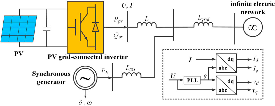
FIGURE 1. Power grid with a PV grid-connected system.
The PV grid-connected system adopts the parallel structure of multiple single-stage inverters, with the same structural and control parameters for each PV module. Pe is the electromagnetic power of the generator, L represents the reactance of the transmission line, Id and Iq denote the d and q-axis components of the PV grid-connected inverter output current, vd and vq denote the d and q-axis components of the bus voltage U at the point at which the PV grid-connected inverter is located. Assuming that the d-axis of the dq reference frame is aligned with the node voltage vector U of the PV grid-connected inverter bus, vd =|U | and vq = 0. The active and reactive power outputs of the PV grid-connected inverter can then be computed as follows (Yang et al., 2018):
When power oscillations occur, key physical quantities such as the rotor speed ω, and the rotor angle δ of the generator will oscillate. In the established model, if the mechanical power of generator Pm remains unchanged during oscillation, the dynamic model of the generator in the system is as follows (Kundur, 1994):
where H and D represent the inertia damping coefficient of the generator in the model and ωr and ω0 represent the rotor speed of the generator and the synchronous speed of the power system. Similarly, the mathematical model above is applicable to large-scale multi-machine power systems containing PV grid-connected systems. During power oscillations in the system, the output power of the generator will also oscillate, causing the rotor speed deviation of the generator to fluctuate near the equilibrium point.
To ensure the stable operation of the power grid, the active power output Ppv and reactive power output Qpv of the PV plant are adjusted to suppress power oscillation. The original control strategy to damp power oscillation in PV grid-connected systems was mainly based on two kinds of parameters: rotor speed ω and rotor angle δ (Figure 2) (Varma and Akbari, 2020). In the control model, I* d and I* q are the current references of the PV grid-connected inverter controller for damping power oscillation.
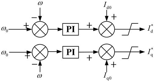
FIGURE 2. Original control model for PV to damp power oscillation.
When the power grid and PV system are operating in a stable state, Id = I* d, Iq = I* q. When the power oscillation occurs owing to disturbances, Id and Iq deviate from the steady-state operating point Id0 and Iq0, with the values depending on the control strategy of the PV grid-connected inverter and the feedback signal of the inverter controller. According to the controller model mentioned above, the equations for I* d and I* q are as follows:
where Kpp, Kip, Kpq, Kiq are the gain parameters of the active and reactive control loop. To prevent inverter overload, the values of I* d and I* q are also limited. According to the inverter power capacity and the maximum power tracking (MPPT) operation mode of the PV system, the constraints of I* d and I* q can be expressed as follows:
Based on the dynamics of the PV grid-connected inverter, the mathematical model can be described as follows:
where ed and eq denote the d and q-axis components at the PV grid-connected inverter output voltage, R and L represent the parasitic arm resistance and inductance of the PV grid-connected inverter, respectively, and ωe denotes the nominal frequency of the external power grid. The dynamics of the capacitor voltage ripple of the bridge arm and the circulating current of the inverter are both neglected in this study, as their timescales are much smaller than those of the power oscillations.
Based on the dynamics of PV grid-connected inverters, the output voltages ed and eq can be estimated as,
where Kp and Ki represent the proportional and integral coefficients of the controller, respectively.
According to the control strategy for the PV grid-connected inverter, the dynamic inverter output current can be obtained under unbalanced power situations. Therefore, the PV grid-connected system can be equivalent to the two current sources controlled by the rotor speed of the power grid generator. These currents are the active and reactive output current (Id and Iq) of the PV grid-connected system. To analyze the dynamic characteristics of the power grid with a PV system under power oscillation, the equivalent system model is shown in Figure 3.
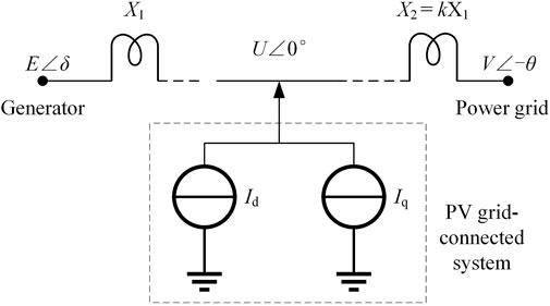
FIGURE 3. Equivalent model of a power grid with PV power generation.
In this figure, E∠δ, U∠0°, and V∠-θ represent the bus voltages at the node of the generator, the PV grid-connected system, and the main grid, respectively. X1 denotes the impedance between the PV system and generator, and X2 denotes the impedance between the PV system and the main grid. Assuming that X2 is equal to kX1, where k denotes the position coefficient of the PV system in the power grid, the greater the value of coefficient k, the farther the distance between the PV system and the power grid. Moreover, assuming that E is equal to V and remains unchanged during operation, the voltage phasor diagram of the equivalent system model is as shown in Figure 4.
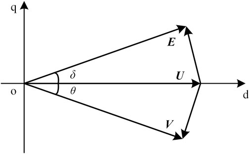
FIGURE 4. Phasor diagram of the system.
According to the voltage phasor diagram of the equivalent system model, the electromagnetic power generated by the generator can be written as:
And the active power absorbed by the main grid can be written as:
Based on Kirchhoff’s Law, the following equation can be given:
The real and imaginary parts of the equation can be written as:
Combining Eqs 10, 11, a new equation that excludes the voltage angle of the main grid can be obtained as follows:
When the voltage amplitude of the generator-side E and the main-grid side V remain unchanged, the voltage amplitude of the PV grid-connected system U is determined by the values of δ, Id, and Iq jointly. Linearization of the above equation results in the following discrete-time model:
where δ0 represents the phase angle of the generator in the steady state and U0 represents the initial voltage value of the PV system grid-connected point. Eq. 13 shows that the output active and reactive power from the PV grid-connected inverter changes the voltage of the PV system grid-connected point U. Therefore, changes in active and reactive power from the PV grid-connected inverter lead to changes in PE and ultimately affect power oscillation. The relationship is given as follows:
where λg, λp, and λq denote the grid synchronization coefficient, the active power control coefficient of the PV system, and the reactive power control coefficient of the PV system, respectively.
To damp power oscillation, this study proposes a control strategy for PV grid-connected inverters to control the output current. However, the power flow calculations within a nonlinear programming algorithm require advanced metering infrastructure (Fu, 2022). Thus, this study adopted a control strategy based on a model predictive control algorithm. The MPC is a promising control method for power-electronic converter systems due to its fast and dynamic response and flexibility to include constraints and nonlinearities of the system (Moon et al., 2015; Rodriguez-Bernuz and Junyent-Ferre, 2020). The proposed control strategy first establishes a discrete-time predictive model of the power grid under power oscillation. A power modulation method based on the MPC algorithm is then adopted to control the output current of the PV grid-connected inverter.
In the MPC algorithm framework, a discrete-time predictive model must be established to predict the value of the system state. In the short time scale, according to the control Eq. 3 of the PV grid-connected inverter, the current reference of the inverter can be obtained in discrete-time form by discretizing the equation:
Similarly, the discrete_time predictive model of the q-axis output current has the same form, which is not described here.
However, in this control mode, the damping of the power grid depends on the size of controller gain parameters Kpp, Kip, Kpq, Kiq. To further increase this damping, a model predictive control strategy is proposed. To ensure the accuracy of the control signal generated by the proposed MPC-based control strategy, it is important to predict the dynamic inverter output current Id and Iq in the time interval between two adjacent control commands.
Based on (Eq. 5), the d-axis output current reference of the PV grid-connected inverter in discrete-time form, with an Euler approximation of the current derivative, is deduced as follows (Qin and Saeedifard, 2012):
In combination with Eqs 5 and 6, the relationship between the d-axis output current reference in the next moment T+1 and the output current reference in current moment T can be written as:
where
Therefore, the independent variables of the prediction model are Id and Iq at the next moment.
where the value of vd (t + T) can be obtained by Eq. 13, and vq = 0 for the q-axis of dq reference frame is perpendicular to the node voltage vector of PV grid-connected point U. The equations of the discrete-time predictive model (19), (23), and (24) provide the basis for the optimal control sequence of the MPC-based controller.
Once the system is disturbed, the dynamics model of the generator described in Eq. 2, can be linearized as follows:
where Δωr(T) represents the rotor angle speed increment of the generator at moment T. Within the sampling period Ts, substituting Eq. 17 into the linearized dynamic model of the generator shows the following:
Therefore, the discrete-time predictive model that can express the change in generator rotor angle speed under power oscillation can be modeled as follows:
where u (t + T) and y (t + T) are the control and intermediate variables of the predicted model at the moment t + T and TP represents the number of steps corresponding to the prediction horizons. According to Eq. 26, the control variables of the PV gird-connected inverter are the reference values of the inverter output current I* d and I* q, and y is the set of variables containing Id, Iq, and δ. Hence, the relationship between the control variable and the rotor angle speed of the generator is established.
According to the predictive model, the relationship between the output current of the PV grid-connected inverter and the rotor angle speed of the generator is obtained. Based on this predictive model, changes in the PV grid-connected inverter output current can directly influence the rotor speed of the generator, which provides the basis for the strategy for damping power oscillations.
The proposed MPC-based control strategy aimed to damp power oscillation. From the above model, I* d and I* q are the control signals of the controller for damping power oscillation. However, the cost of the MPC-based controller to predict the state value of the power grid and solve the objective function must also be considered. To ensure controller rapidity, it only selected I* d as the output control signal in this study. Therefore, the control variable u (t + T) of the proposed MPC-based control strategy is given as follows:
The proposed MPC-based control strategy aims to minimize the rotor angle variations of the center of inertia (COI) during power oscillation. The control cost also needs to be considered. Therefore, the objective function of the MPC-based control strategy is defined as follows:
where λ1 and λ2 denote the control weight, MT represents the overall inertia of the system, and δ0 COI represents the initial rotor angle of COI of the power grid. Moreover, the control variables are bounded between the upper and lower limits for the operating security of the system:
The proposed MPC-based control strategy of the PV grid-connected inverter is conceptually represented in Figure 5.
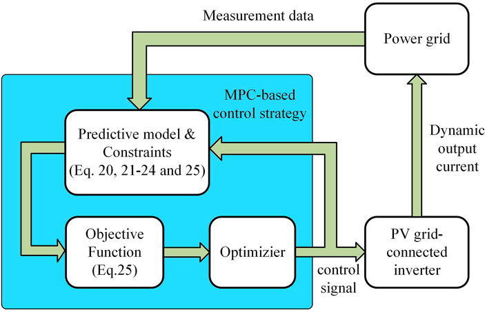
FIGURE 5. Block diagram of the proposed MPC-based control strategy.
This section extensively tests an IEEE-9 bus system with a PV grid-connected system. The layout of the test system is shown in Figure 6. The network and parameters of the synchronous generators in the system were as described previously (Kundur, 1994). The power grid power base was 100 MW and the rated active power output of the PV system was set to 50% of the power base. The PV grid-connected system was assumed to have power storage devices for emergencies. The operational parameters of the PV grid-connected system are as follows: fn = 50 Hz, M = 3, V* dc = 140 kV, Carm = 1070 μF, R = 0.56 Ω, L = 20 mH. The parameters of the PI controllers of the PV grid-connected inverter are: Kp = 4, Ki = 80, Kpp = Kpq = 2000, Kip = Kiq = 10,000. The parameters of the MPC controller are: λ1 = 20, λ2 = 0.01. The prediction window size TP of MPC is set to five steps. The simulations in this study were performed using MATLAB R2014a on a PC with an i7-6700 3.4 GHz CPU and 32 GB RAM.
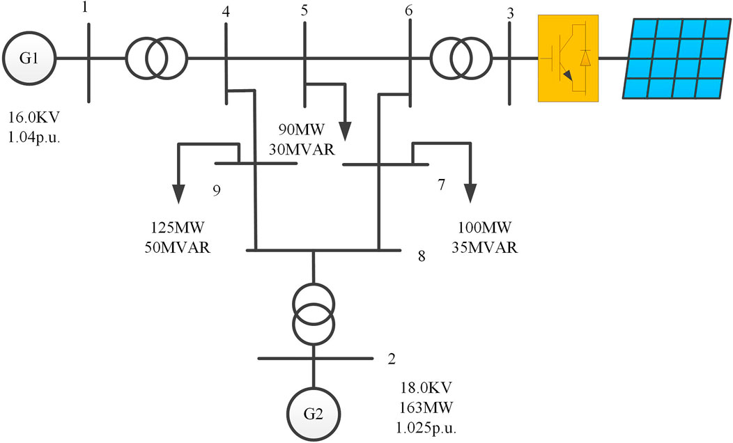
FIGURE 6. Layout of a power system with PV plant.
Assuming that the power system operates under normal operating conditions with a least-acceptable damping ratio of 3% to verify the effect of the proposed control strategy, a three-phase short circuit occurs at 0.8 s on bus 1, where the generator is located, and the fault is cleared after 0.2 s. The time-domain simulation is shown in Figure 7. The ordinate values in Figures 7A,C show the per-unit active electromagnetic output power and active power output of the PV system. The actual values can be obtained by multiplying them by 103 MW.
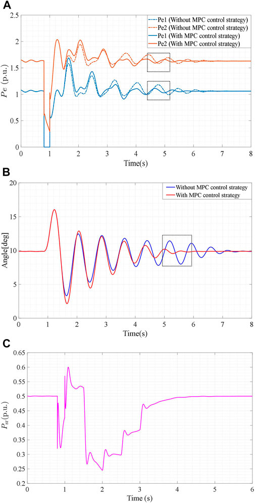
FIGURE 7. (A): Dynamic performances of the active electromagnetic output powers Pe1 and Pe2. (B): Transient angles of generator 1 δ1 in the power grid. (C): Active power output of the PV system.
As shown in Figure 7A under the same situation, the power oscillation amplitude of the electromagnetic powers Pe1 and Pe2 using the proposed MPC control strategy are <0.1 p.u. during 4.5–5 s, while the power oscillation amplitude of the electromagnetic power Pe1 and Pe2 without the MPC control strategy are still >0.15 and 0.2 p.u. The dynamic performance of rotor angle δ1 is shown in Figure 7B. The oscillation amplitude of δ1 is <1° during 5–5.5 s when using the proposed control strategy. The oscillation amplitude of δ1 is still >4° at 5–5.5 s when the proposed MPC control strategy is not used in the control process. Figure 7C shows that reducing the active power output of the PV system when this fault occurs will increase the damping. Under the response of the proposed MPC control strategy, the active power injection of the PV grid-connected inverter is reduced to around 0.2 p.u. at 0.5 s after the fault occurs, and then gradually recovers to the original power output within a certain control period.
Therefore, the results demonstrated a significant improvement in damping effectiveness when the MPC control strategy was used. The proposed MPC control strategy can address power oscillations of the power grid when faults occur at the generator bus and can be used in PV grid-connected DC transmission technology.
This case assumes that a three-phase short circuit fault occurs at 1 s on bus 6, which is the point of common coupling between the main grid and the PV system, which is cleared after 0.1 s. The simulation results are shown in Figure 8.
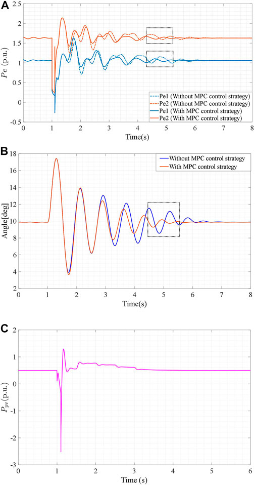
FIGURE 8. (A): Dynamic performances of the active electromagnetic output powers Pe1 and Pe2. (B): Transient angles of generator 1 δ1 in the power grid. (C): Active power output of the PV system.
As shown in Figure 8A, in the case of this fault, the power oscillation amplitudes of the electromagnetic powers Pe1 and Pe2 with the proposed MPC control strategy are <0.1 p.u. during 4.5–5 s, compared to nearly 0.15 p.u. without an MPC control strategy. The dynamic performance of rotor angle δ1 is shown in Figure 8B. The oscillation amplitude of δ1 is <1° during 5–5.5 s when using the proposed control strategy, compared to nearly 7° without the MPC control strategy. Unlike Case 1, Figure 8C shows that increasing the active power output of the PV system also suppresses power oscillations. When the three-phase grounding fault occurs at the point of common coupling and is cleared after 0.2 s, the active power injection of the PV grid-connected inverter increases to 0.8 p.u. at 2 s and then gradually reduces to the original power output within a certain control period.
The results showed that the proposed MPC control strategy enhanced the ability of a power grid with a PV system to dampen power oscillations. Therefore, the proposed control strategy can improve the transient stability of the power grid with PV power generation and reduce the risk of operation instability in case of fault.
This case assumes that a 0.1 s three-phase short circuit fault occurs at 1s on load bus 7, resulting in emergency load shedding and generator rescheduling. Bus 7 sheds its 20 MW power load and generator two generates 132 MW power according to the generator rescheduling. Figure 9 illustrates the dynamic performance of the power grid with PV power generation after contingency.
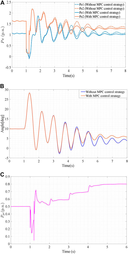
FIGURE 9. (A): Dynamic performances of the active electromagnetic output powers Pe1 and Pe2. (B): Transient angles of generator 1 δ1 in the power grid. (C): Active power output of the PV system.
As shown in Figure 9A, the end time of the power oscillation in the case with an MPC control strategy is significantly shorter than that without an MPC control strategy. Moreover, the oscillation process of rotor angle δ1 as shown in Figure 9B, also demonstrates the positive effect of the MPC control strategy on suppressing power oscillation. Figure 9C illustrates the dynamic performance of the PV system’s active power output, in which the PV system must continuously and rapidly provide higher active power output to maintain power grid stability.
The results showed that the proposed PV grid-connected inverter structure and control strategy addressed the uncertainty of the power generated by PV plants and can be used in PV grid-connected DC transmission technology.
Above all, the results of the simulations showed that the proposed MPC control strategy can quickly suppress power oscillations of the power grid with PV power generation under various faults to improve the operational security of the power grid.
To solve the problem of frequent power oscillation in power systems caused by reduced inertia and damping capacity, the present study proposed an MPC-based control strategy for PV grid-connected inverters. Based on the dynamic characteristics of the PV system and the control strategy for the PV grid-connected inverter, the proposed MPC-based control strategy adjusts the output current of the PV grid-connected inverter to reduce the rotor angle amplitude of the synchronous generator in the power system. The simulation results showed that the proposed MPC-based control strategy increased the damping of the power system under disturbances, thereby quickly dampening the power oscillations. The main advantage of the proposed control strategy is that it improves the power damping oscillation of the power system by controlling the active power output of the PV grid-connected inverter, thereby reducing the adverse effects of a PV grid-connected station. This is of great significance for the promotion of large-scale PV power stations. Future studies will aim to reduce the computational complexity and increase the application scenarios.
The original contributions presented in the study are included in the article/Supplementary Material. Further inquiries can be directed to the corresponding authors.
XW contributed to all aspects of this work and conducted the data analysis. HJ, TW, HW, and JP provided comments and suggestions and affected the process of the research. All authors reviewed the manuscript.
This project was supported by the National Natural Science Foundation of China (grant 52177102), the Natural Science Foundation of Guangdong Province (grant 2021A1515011685), Shenzhen International Cooperation Research Project (grant GJHZ220180928160212241), and a Shenzhen Basic Research Project (grantJCYJ20190808165201648).
The authors declare that the research was conducted in the absence of any commercial or financial relationships that could be construed as a potential conflict of interest.
All claims expressed in this article are solely those of the authors and do not necessarily represent those of their affiliated organizations, or those of the publisher, the editors and the reviewers. Any product that may be evaluated in this article, or claim that may be made by its manufacturer, is not guaranteed or endorsed by the publisher.
Ahmad, S., Alhaisoni, M. M., Naeem, A., Ahmad, A., and Altaf, M. (2020). Joint energy management and energy trading in residential microgrid system. IEEE Access 8, 123334–123346. doi:10.1109/ACCESS.2020.3007154
Alquthami, T., Ravindra, H., Faruque, M. O., Steurer, M., and Baldwin, T. (2010). Study of photovoltaic integration impact on system stability using custom model of PV arrays integrated with PSS/E in Proc. North Amer. Power Symp. Arlington, TX, USA 26-28 September IEEE, 1–8. doi:10.1109/NAPS.2010.5619589
Berizzi, A. (2004). The Italian 2003 blackout. in Proceedings of the IEEE Power Engineering Society General Meeting Denver, CO, USA 06-10 June 2004 2. IEEE, 1673–1679. doi:10.1109/PES.2004.1373159
Bian, X. Y., Geng, Y., Lo, K. L., Fu, Y., and Zhou, Q. B. (2016). Coordination of PSSs and SVC damping controller to improve probabilistic small-signal stability of power system with wind farm integration. IEEE Trans. Power Syst. 31 (3), 1–12. doi:10.1109/TPWRS.2015.2458980
Carrasco, J. M., Franquelo, L. G., Bialasiewicz, J. T., Galvan, E., PortilloGuisado, R. C., Prats, M. A. M., et al. (2006). Power-electronic systems for the grid integration of renewable energy sources: A survey. IEEE Trans. Ind. Electron. 53 (4), 1002–1016. doi:10.1109/TIE.2006.878356
Fu, X. (2022). Statistical machine learning model for capacitor planning considering uncertainties in photovoltaic power. Prot. Control Mod. Power Syst. 7 (5). doi:10.1186/s41601-022-00228-z
Heidari, Y. S. S., Rahimi, T., Khadem, H. S., Bagheri, M., and Gharehpetian, B. G. (2022). Over-voltage regulation of distribution networks by coordinated operation of PV inverters and demand side management program. Front. Energy Res. 10, 920654. doi:10.3389/fenrg.2022.920654
Li, H., Li, H., Wang, Z., and Bian, J. (2020). Optimal power flow calculation considering large-scale photovoltaic generation correlation. Front. Energy Res. 26, 8. doi:10.3389/fenrg.2020.590418
Maleki, H., and Varma, R. K. (2016). Coordinated control of PV solar system as STATCOM (PV-STATCOM) and Power System Stabilizers for power oscillation damping in Proceedings of the IEEE Power and Energy Society General Meeting (PESGM) 17-21 July 2016 Boston, MA, USA IEEE, 1–5. doi:10.1109/PESGM.2016.7741813
Mithulananthan, N., Canizares, C. A., Reeve, J., and Rogers, G. J. (2003). Comparison of PSS, SVC, and STATCOM controllers for damping power system oscillations. IEEE Trans. Power Syst. 18 (2), 786–792. doi:10.1109/TPWRS.2003.811181
Moon, J., Gwon, J., Park, J., Kang, D., and Kim, J. (2015). Model predictive control with a reduced number of considered states in a modular multilevel converter for HVDC system. IEEE Trans. Power Deliv. 30 (2), 608–617. doi:10.1109/TPWRD.2014.2303172
Prasertwong, K., Mithulananthan, N., and Thakur, D. (2010). Understanding low frequency oscillation in power systems. Int. J. Electr. Eng. Educ. 47, 248–262. doi:10.7227/IJEEE.47.3.2
Qin, J., and Saeedifard, M. (2012). Predictive control of a modular multilevel converter for a back-to-back HVDC system. IEEE Trans. Power Deliv. 27 (3), 1538–1547. doi:10.1109/TPWRD.2012.2191577
Reigstad, T. I., and D’Arco, S. (2022). A special protection scheme for damping power system oscillations by controlling wind farms. Electr. Power Syst. Res. 211, 108306. doi:10.1016/j.epsr.2022.108306
Rodriguez-Bernuz, J., and Junyent-Ferre, A. (2020). Operating region extension of a modular multilevel converter using model predictive control: A single phase Analysis. IEEE Trans. Power Deliv. 35 (1), 171–182. doi:10.1109/TPWRD.2019.2908695
Simoes, A. M., Savelli, D. C., Pellanda, P. C., Martins, N., and Apkarian, P. (2009). Robust design of a TCSC oscillation damping controller in a weak 500-kV interconnection considering multiple power flow scenarios and external disturbances. IEEE Trans. Power Syst. 24 (1), 226–236. doi:10.1109/TPWRS.2008.2006999
Varma, R. K., and Akbari, M. (2020). Simultaneous fast frequency control and power oscillation damping by utilizing PV solar system as PV-STATCOM. IEEE Trans. Sustain. Energy 11 (1), 415–425. doi:10.1109/TSTE.2019.2892943
Varma, R. K., and Maleki, H. (2019). PV solar system control as STATCOM (PV-STATCOM) for power oscillation damping. IEEE Trans. Sustain. Energy 10 (4), 1793–1803. doi:10.1109/TSTE.2018.2871074
Yang, B., Jiang, L., Yu, T., Shu, H., Zhang, C., Yao, W., et al. (2018). Passive control design for multi-terminal VSC-HVDC systems via energy shaping. Int. J. Electr. Power & Energy Syst. 98, 496–508. doi:10.1016/j.ijepes.2017.12.028
Keywords: PV grid-connected inverter, model predictive control, power oscillations, power grid, dynamic optimization
Citation: Wen X, Wu T, Jiang H, Peng J and Wang H (2022) MPC-based control strategy of PV grid connected inverter for damping power oscillations. Front. Energy Res. 10:968910. doi: 10.3389/fenrg.2022.968910
Received: 14 June 2022; Accepted: 10 August 2022;
Published: 13 September 2022.
Edited by:
Xueqian Fu, China Agricultural University, ChinaReviewed by:
Sadiq Ahmad, COMSATS University Islamabad, Wah Campus, PakistanCopyright © 2022 Wen, Wu, Jiang, Peng and Wang. This is an open-access article distributed under the terms of the Creative Commons Attribution License (CC BY). The use, distribution or reproduction in other forums is permitted, provided the original author(s) and the copyright owner(s) are credited and that the original publication in this journal is cited, in accordance with accepted academic practice. No use, distribution or reproduction is permitted which does not comply with these terms.
*Correspondence: Jianchun Peng, amNwZW5nQHN6dS5lZHUuY24=; Huaizhi Wang, d2FuZ2h6QHN6dS5lZHUuY24=
Disclaimer: All claims expressed in this article are solely those of the authors and do not necessarily represent those of their affiliated organizations, or those of the publisher, the editors and the reviewers. Any product that may be evaluated in this article or claim that may be made by its manufacturer is not guaranteed or endorsed by the publisher.
Research integrity at Frontiers
Learn more about the work of our research integrity team to safeguard the quality of each article we publish.