 Magdi G. Muftah1
 Mohamed Salem
 Yonis M. Buswig
 Mohamad Kamarol
- 1School of Electrical and Electronic Engineering, Universiti Sains Malaysia, Nibong Tebal, Penang, Malaysia
- 2Institute of Sustainable and Renewable Energy ISuRE, Faculty of Engineering, University Malaysia Sarawak, Kota Samarahan, Malaysia
- 3Faculty of Engineering, Department of Electrical and Electronic Engineering, Fezzan University, Fezzan, Libya
- 4Mechatronics Engineering Department, Cape Peninsula University of Technology, Cape Town, South Africa
Power generating entities’ connection to utility grids requires power converters to achieve high efficiency and low injected current harmonic distortion. The control of the power converter plays a crucial role in the grid-tied power converter’s performance. Various control techniques for grid-tied inverters ranging from classical to intelligent are introduced in several exist. Evaluating the current state and trend in grid-tied power inverters and related control methods, research shows that most works in this area focus on grid integration using the close-loop and other advanced control approaches. This is because these control methods are preferred since they provide adequate performance in case of uncertainties in the system. This investigation can aprove that PQ open-loop control technique can operate sufficiently and cost-effectively in grid-tied renewable and alternative power systems under normal operating conditions. Hence, this paper aims to assess the performance of a centralized single-stage grid-tied three-level diode clamped inverter connected to a PV-Fuel cell unit. An active and reactive power open-loop control scheme is employed to operate the inverter and achieves a current harmonic distortion below 5%. The system comprises a 150 kW/700 V PV, a 150 kW/1400 V fuel cell, a 265 kW multilevel inverter operating at a rated voltage of 415 V, and an LCL filter. Two operating scenarios are adopted to investigate the system’s responses further. In the first scenario, a local load of 509.2 kW is supplied from the PV-fuel cell inverter. The load also receives the grid’s power to meet the demand as the PV-fuel cell inverter provides only 265 kW. Whereas in the other scenario, the PV-fuel cell unit provides power to supply a local load while transporting the surplus to the grid. The results reveal the developed model’s good performance with a current harmonic distortion of 0.33%.
1 Introduction
Restructuring the electricity system from vertically into a horizontally integrated system opens the door for many innovative system design and operation ideas. The technological advancement of distributed generation technologies and the significant concerns over fossil fuel consumption’s negative environmental impact shifted the traditional way of designing and operating electric power systems. Distributed energy resources are now integral parts of modern power systems. They consist of power generating units such as the fuel cell (FC) system, solar PV, solar thermal, wind energy conversion system, wave energy harvester, biogas, diesel generators, energy storage systems, and different technologies controllable electric loads. Such power generating entities’ connection to utility grids requires power converters to condition the power generated and guarantee power quality when operating tied to the grid (Yu et al., 2007; Gao et al., 2009). The grid-tied power converter must achieve high efficiency and low injected current harmonic distortion while regulating the power exported to the grid. The inverter control scheme plays a crucial role in the grid-tied power converter’s performance; it manages the dc-link voltage and adjusts the power injected into the grid. Two power converter topologies are predominant for grid-tied distributed power systems, namely a one-stage power converter (1-SPC) consisting only of a grid-connected inverter via a power transformer and a two-stage power converter (2-SPC) that consists of DC/AC and DC/DC converters (Gao et al., 2009). Nonetheless, the two-stage power converter is more favored due to its advantages, such as operating under a broad voltage range. This guarantees a decent energy conversion.
Furthermore, the topology decouples the distributed generation unit from the inverter terminals to prevent the induction of double-line-frequency ripple by the ripple of the AC power. The 1-SPC is once again the most cost-efficient configuration as it requires no DC/DC converter (Xiao et al., 2016). This configuration is not popular because of the need for the minimum dc-link voltage is supposed to be greater than the peak grid voltage required to prevent over-modulation system operation. Although both 1-SPC and 2-SPC can be designed in centralized, multi-string, and string structures, the implementation of different types of 1-SPC, ranging from low to high levels, is a function of the power specification (Islam and Mekhilef, 2014). For instance, the 2-SPC arrangement is the most utilized inverters for low power and low voltage usages.
Similarly, for applications with high-power requirements, the multilevel inverter is more appropriate (Çelik et al., 2018). Multilevel inverters (MLIs) may also be utilized in medium to high voltage applications, such as power distribution, motor drives, etc. (Mancilla-David et al., 2012). However, several design trade-offs govern the decision on the type of MLI structure and the suitable control scheme to be used (Marx et al., 2014). Nevertheless, the most developed multilevel inverter arrangements comprise the Diode Clamped, the Flying Capacitor inverter, and the Cascade Full Bridge (Lai and Ellis, 2017). Amongst them, the three-level diode-clamped inverter is one of the most commercially used topologies.
Additionally, inverters’ most well-known control scheme is the closed-loop control scheme consisting of the DC voltage and inner current controls. Four closed-loop control strategies are generally employed for regulating current injected into the grid, namely the direct control with current feedback on either the grid side or inverter-side inductor, the cascade control with either the capacitor current feedback or the inverter-side inductor current that serves as the inner loop (Mahlooji et al., 2018). In the direct control technique, the grid injected and the reference currents are compared, and the resulting error serves as the input to a PI controller; this aids steady-state error elimination. In this configuration, the output of the PI controller serves as the inverter voltage reference. Both the grid and inverter voltages determine the current fed to the grid.
Regarding the cascade control current feedback on the inverter side, the current feedback on the grid side inductor acts as the external loop, while the current feedback on the inverter-side inductor is the internal loop. Similarly, the active and reactive power (PQ) open-loop control scheme is also suitable for the control of inverters. The control is designed either in a stationary or in a synchronous frame (Teodorescu et al., 2011). The control carried out in a synchronous frame regulated the active and reactive power by using a current regulator implemented in the dq0 frame and feed-forward. The regulation of the DC voltage provides the active power reference. Whereas in the stationary frame, the control is achieved in the αβ0 frame, prompting an indirect voltage-oriented control scheme. The approach requires the feed-forward regulation of the active and reactive power, with the control of the DC voltage following up the power reference (Teodorescu et al., 2011). As mentioned above, the power system is undergoing a major shift from centralized power generation to distributed power generation. More and more distributed generators (DGs) are connected to the grid through power inverters. To cut down the impact of many inverters tied to the grid, the inverters’ control scheme must be carefully designed. In the same vein, the inverter is the critical interface for DGs in smart grids. Hence, it is important to determine the appropriate control strategy to ensure a smart and friendly connection of the DG to the grid for smart grid management (Hornik and Zhong, 2012). Various control techniques for grid-tied inverters ranging from classical to intelligent are introduced in several studies (Hornik and Zhong, 2012; Zeb et al., 2018). The PQ open-loop control technique refers to a classical inverter control method. Evaluating the current state and trend in grid-tied power inverters and their existing control methods showed that most works in this area have focused on grid integration using the close-loop control approach. This is because the control method is preferred since it improves adequate performance due to uncertainties in the system. However, research also shows that the PQ Open-loop control technique can operate sufficiently and cost-effectively in most applications (Hornik and Zhong, 2012). Hence, the major aim of this work is to present a detailed design and simulation for the effective implementation of a three-level inverter controlled through a PQ open-loop control scheme in a grid-tied PEMFC and provide adequate power quality features.
Thus, the main idea of this paper is to evaluate the performance of a centralized grid-tied one-stage three-level diode clamped inverter connected to a hybrid PV- FC. A synchronous PQ open-loop control scheme is employed to operate the inverter and achieves a current harmonic distortion of below 5%. Apart from the grid, the system comprises a 150 kW/1400 V FC, 150 kW/700 V PV array, a 265 kW/415 V inverter, and a passive LCL filter that connects the grid and the inverter. The system performance was further evaluated using two operating scenarios. In scenario one, the hybrid PV- FC produces power to feed a neighborhood load while also transferring the surplus to the grid. In the other scenario, a neighborhood load of 365 kW received power from the grid-tied PV- FC inverter. The load also imports power from the grid to meet the 365 kW demand because the hybrid PV- FC only produces 265 kW. The investigation showed that the proposed system performed well with about 0.33% current harmonic distortion.
The rest of the paper is organized as follows: Section 2 povides a review of related works in literature. Section 3 presents the investigated system. Section 4 provides the methodology utilized to carry out this investigation. Section 5 deals with system modeling. Section 6 is devoted to the outcomes and discussion, and the last section closes this research and provides proposals for future studies.
2 Literature review
The literature contains several publications on inverter control techniques for grid-tied renewable and alternative power systems. However, there is less emphasis on the single loop voltage-oriented control, including a current controller implemented in the DQ frame and active and reactive power feed-forward control.
Khan et al. (2020) presented an in-depth analysis of grid-connected solar inverters, their modulation methods, and control strategies. The authors presented grid-connected inverter configurations and classifications. Different multilevel inverter topologies and modulation methods were categorized and expounded in great detail. Various control reference frames for inverters were also described. Additionally, various inverter control schemes were described.
The grid integration of other sustainable energy technologies, such as solar systems, wind turbines, etc., is emphasized in many research studies. A thorough examination of the dynamic behavior and transient features of a doubly fed induction generator during grid faults and voltage sags was presented by Khan et al. (2019). To reduce the negative effects of an imbalanced grid voltage DC capacitor and enable harmonic filtering to enhance power quality, novel grid side controllers, adaptive proportional-integral controllers, and proportional resonant with a resonant harmonic compensator were introduced. A suggested algorithm reduces harmonic currents, voltage fluctuations, and distorted active and reactive power sent to the electric grid, making capacitors more reliable under transient grid conditions. A simulation was run to verify the efficacy of the suggested control algorithms. The findings demonstrated the proposed controller’s robustness, lack of ripples, and fault tolerance. A grid-tied 50 kW solid oxide fuel cell with synchronous reference frame (SRF) control was examined by Das.
Das Gupta et al. (2017). A double-stage inverter was used to tie the system to the grid. The study focused on the performance evaluation of the system. The findings demonstrated that when fuel cell current and power grow, fuel cell stack voltage steadily declines. It took 5 s for the stack’s voltage, current, and power to stabilize. This sluggish response was brought on by the cells’ gasses’ delayed chemical reactions. The active and reactive power fed to the grid under the proposed SRF control approach took 2 s to attain the required nominal.
A study on the modeling and control of a modular multilevel converter for the grid integration of photovoltaic units was conducted by Hakimi and Hajizadeh (2018). A dynamic model of a modular multilevel converter was put forth that included symmetrical voltage and current components. Sliding mode and fuzzy controllers were used to produce adaptive robust current controllers. Current controllers were implemented to account for grid voltage fault and load power variation to actualize the suggested controllers under unbalanced grid voltage fault, positive and negative sequences. The outcomes showed that the suggested current controllers could satisfy the stability requirements of the modular multilevel converter and are more efficient under voltage disturbance situations.
Miret et al. (2013) proposed a single loop control scheme with voltage support ability for grid-connected distributed generator inverters operating under voltage sag. One of the key issues in transmission and distribution grids with significant penetration of distributed power is voltage sags. This research suggested a voltage support control technique for grid-connected power sources in response to voltage sags. The injection of reactive current with a changeable ratio of positive to negative sequences served as the basis for the control. The controller also decided how much reactive power is required to bring the lowered voltage magnitudes back to new reference levels constrained by the grid codes’ requirements for continuous operation. These reference values ensure low current injection when achieving the voltage support aim. A few experimental findings were provided to verify the suggested control’s efficacy.
Chilipi et al. (2016) proposed a control strategy for a grid-tied distributed generation inverter in distorted and unbalanced utility conditions. The study suggested a grid-interfaced distributed generation inverter control scheme with a novel fundamental sequence components extractor. Third-order sinusoidal signal integrator-based frequency adaptive filters were used to implement the proposed sequence extractor. Under distorted grid conditions, it had a great ability to separate the three-phase voltage and current signals into positive and negative sequence components. In addition to basic power injection, the suggested control method could deliver power quality ancillary services, including reactive power compensation and harmonics rejection. It was also immune to frequency changes. Simulation and experimental research assessed the suggested system’s performance under various grid disturbances and loading situations.
Modeling (2016) proposed a novel robust and adaptive sliding-mode control for a grid-connected photovoltaic (PV) system based on cascaded two-level inverters. The control scheme was modeled and designed to deliver active and reactive power with changeable solar irradiation for the cascaded two-level inverters-based grid-connected PV system. The development of a vector controller considers the PV’s ability to provide maximum power. When designing SM controllers, two switching strategies were considered and investigated in similar operating circumstances. The suggested SM controller operates using a straightforward PWM modulation technique rather than the referenced space vector pulse width modulation (PWM) technique. Utilizing an adaptive hysteresis band computation enhances the performance of the SM controller. Liu et al. (2014) presented a unified control technique for there-phase grid-tied inverter in distributed generation. With no need to switch between two corresponding controllers or perform key islanding detection, the unified control method presented in this work permits both islanded and grid-tied operations of three-phase inverters in distributed generation. The suggested control technique consists of a novel voltage loop in the synchronous reference frame and an inner inductor current loop. In grid-tied operation, the inverter is only regulated as a current source by the inner inductor current loop. The voltage controller is immediately triggered to regulate the load voltage when islanding occurs. The literature review above refers to grid-tied three-phase inverter classical control techniques. However, other research focuses on more advanced methods; Tan et al. (2013) proposed a coordinated control distributed generation inverters. A new model predictive control technique was used in the control design of the DG inverters to enable shorter computation times for large power systems by independently optimizing the steady-state and transient control problems. The proposed microgrid’s operating capabilities were demonstrated through various test scenarios that validate the design concept, and the results were described.
Ro and Rahman (1997) used a two-loop controller to maximize the performance of a grid-tied photovoltaic-fuel cell plant. In one loop, a neural network controller for maximum power point tracking collected the most solar energy from PV arrays under a range of insolation, temperature, and system load circumstances. The second loop was a genuine reactive power controller. The real/reactive power controller managed incoming fuel to fuel cell stacks and switched control signals to a power conditioning subsystem to meet the system’s demands for actual and reactive powers. Time-domain simulation results demonstrated the two-loop controller’s effectiveness and suitability for use in stability analysis of the hybrid power plan, in addition to demonstrating how well they could be implemented in computer models.
Ouchen et al. (2016) suggested a real-time implementation of a shunt active power filter coupled with a double-stage grid-connected PV inverter. A predictive direct power control model was used to ensure both meet a portion of the load demand with the extracted solar power and compensate for unfavorable harmonic contents of the grid current under a unity power factor operation. The findings demonstrated that, when operating at unity power, the predictive power control ensured a flexible settlement of active power amount exchanges with the grid. The grid current had a sinusoidal shape and a reasonable overall harmonic distortion value of 4.71%.
The main goal of this literature study was to assess related research on grid-tied inverter control techniques. These article evaluations show that few studies concentrate on the classical single loop voltage-oriented control, including a current controller implemented in the DQ frame and active and reactive power feed-forward control. The primary contribution of this investigation is to show, through careful modeling and simulation, that a multilevel inverter can efficiently operate under PQ single control strategy while providing fast voltage and current responses and low harmonic distortion.
3 Description of the investigated system
Figure 1 depicts the grid-tied PV- FC unit adopted in this study. The PV array produces 150 kW at 700 V and consists of 28 strings of 20 modules generating 280.2 W each. While the FC stack generates 150 kW at 1400 V. The PV is tied in parallel with the FC stack through a DC/DC boost converter to ensure that both the PV and FC are at the same voltage level. The proposed hybrid power unit is connected to the grid via a three-level neutral point clamped inverter; the system has a DC-link capacitor in-between the DC bus and the DC terminals of the inverter; this positioning is to eliminate the ripples and maintain an almost steady DC voltage. On the AC side, an LCL filter joins the AC terminals of the inverter and the grid to mitigate harmonic effects.
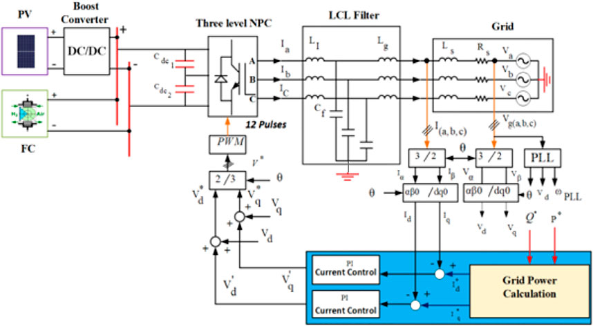
FIGURE 1. On-grid-hybrid PV- FC system.
The hybrid PV- FC system is viewed from the grid as a 300 kW generating power unit operating at 415 V. The adopted control scheme regulates the power flow between the different power entities involved. Furthermore, it controls the hybrid PV- FC unit’s frequency and phases to meet the grid requirements.
4 System modeling
4.1 Photovoltaic system
Eq. 1 expresses the output characteristics of a photovoltaic cell (Salilih and Birhane, 2019):
The definitions of parameters of Eq. 1 are as follows:
In general, the expression
Solving Eq. 3 requires determining the parameters
4.1.1 Parameters estimation
The estimations of parameters
• Estimating the thermal voltage
The thermal voltage refers to the average energy of numerous particles traveling randomly at a specific temperature obtained from the manufacturer datasheet at a set reference point from Eq. 4 given as (Tesfahunegn, 2012):
where
Eq. 6 determines the thermal voltage (Tesfahunegn, 2012):
• Estimating the series resistance
The series resistance value is either provided by the manufacturer or determined using Eq. 7 (Tesfahunegn, 2012):
where
• Estimating the current
Eq. 8 defines the photon current (Tesfahunegn, 2012):
• Estimating the saturation current
The saturation at a reference point is estimated using Eq. 9 as follows (Tesfahunegn, 2012):
The saturation current is determined based on Eq. 10 as (Tesfahunegn, 2012):
4.1.2 DC/DC converter design
A boost converter’s main components are a diode, an inductor, and a high-frequency switch (IGBT). The control strategy lies in manipulating the switch’s duty cycle, which causes the voltage change (Raju and Tharun Kumar, 2017). The parameters of a DC/DC boost converter during continuous mode operation are given in the following equations (Elbaset et al., 2016; Satpathy et al., 2016; Chen et al., 2017):
Where
Table 1 provides the PV array modeling features and the DC/DC boost converter parameters. While Figure 2 gives the PV maximum power, voltage, and current curves.
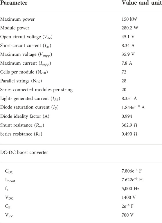
TABLE 1. PV system characteristics.
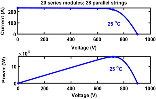
FIGURE 2. PV array characteristics.
4.2 Fuel cell
The definition of the dynamic fuel model is presented as follows (Hamad et al., 2021), (Hamad et al., 2021):
Where
Where
The modelling parameters of the FC are given in Table 2, whereas Figure 3 provides the stack power, voltage and current features.
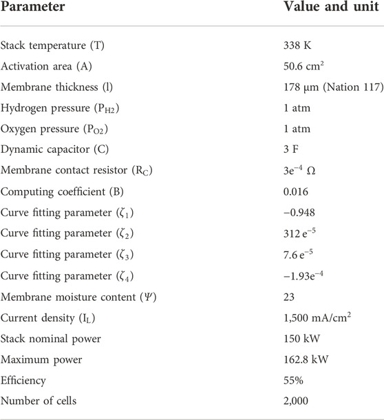
TABLE 2. Fuel cell characteristics.
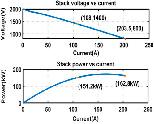
FIGURE 3. Fuel cell stack characteristics.
4.3 Three-level diode clamped inverter
The generation of almost sinusoidal three-level (3-L) AC waves by the 3-L diode clamped inverter relies on the use of cascaded DC capacitors and clamping diodes, with the process being implemented at a low switching frequency that requires less filtering components, while the level of harmonic distortion is relatively low (Shriwastava et al., 2016; Wu et al., 2018). The output voltage of the 3-L inverter comes from the switching operation of the switching components. As seen in Table 3, consider
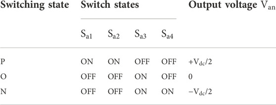
TABLE 3. Switching states Three-level diode clamped inverter (Chaturvedi et al., 2008).
4.4 Control scheme
A current regulator implemented in the dq0 frame was used together with the active and reactive feed-forward power control as the control strategy in this work. Figure 4 depicts the description of the open loop control scheme used. The DC voltage control aided in actualizing the active and reactive reference power control; this demands the transformation of the reactive and active power command signals into the reference current’s d and q components using the following matrix (Hamad and Luta, 2021):
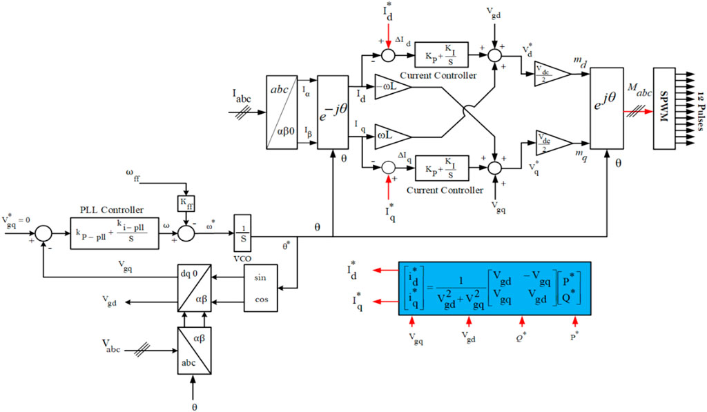
FIGURE 4. Open-loop control scheme.
4.4.1 Current control
The dynamics of the control loops of the current control are similar in the d and q axis; hence, only the d axis is subjected to PI controller tuning since there is a consideration of equality of the parameters of the q axis. As shown in Figure 5, it is considered that both the feed-forward voltage and the decoupling between both axes (d and q) are noise, and are neglected (Keawthai and Po-Ngam, 2015).
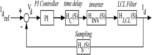
FIGURE 5. Current control loop block diagram.
Figure 5 depicts the illustration of the current loop’s transfer function:
However, the simplified transfer function of the current loop is given as (Hamad and Luta, 2021):
From Eq. 25,
4.4.2 Phase-locked loop
The representation of the dq0 frame PLL includes a PI controller (serving as the loop filter), a voltage-controlled oscillator (VCO) (integrator), and Clarke and Park transformations (Ali et al., 2018). The transfer function
where
The gains
4.5 LCL filter design
The LCL filter design requires the following as the input parameters:
4.5.1 Critical frequency
The following equations defined the critical frequency
Where the critical frequency is given as
4.5.2 Resonance frequency
Eq. 33 is used to determine the resonance frequency
It is important to ensure the satisfaction of the inequality in Eq. 34.
4.5.3 Constant correlation
The inverter-side and the grid side inductances constant correlation
where
4.5.4 Capacitor
The capacitor value is provided in Eq. 37:
Where
4.5.5 Converter-side and grid-side inductances
Eq. 37 computes the product
From the product
4.5.6 Current ripple
Eq. 38 gives the value of the current ripple
The value of the ripple current must be within 10%–25% of the peak rated current
where
4.5.7 Damping resistor
The impedance of the LCL filter at the resonance frequency = 0 while the magnitude response is normally high; hence,
5 Results and discussion
The modeling and simulation of the grid-tied hybrid PV- FC unit in Figure 1 was done in a Matlab/Simelectrical (R2020B) environment for the assessment of the performance of the proposed system using the metrics in Tables 1, 2, 4–6. The simulation results are presented in the following sub-sections, and consist of analyzing the control parameters results, the system frequency and phase, and the inverter output features. Furthermore, two operating scenarios are considered to evaluate the system’s performance. A sensitivity analysis is also carried to assess the system’s response under abnormal parameter changes and unbalance faults operations.
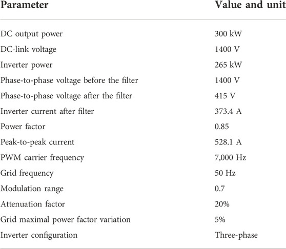
TABLE 4. Inverter design parameters.
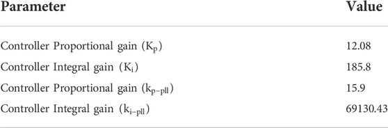
TABLE 5. Control parameters.
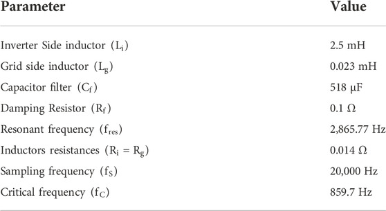
TABLE 6. LCL filter parameters.
5.1 Control
The overall control results show that the developed controller displays a decent response. Figure 6A depicts the d axis current (Id) and the reference current on the d axis (Id_ref). The current controller in the d-axis relies on the resulting error from the comparison of both currents as the input signal to produce the voltage on the d axis (Vd). The Id_ref is around 521.2 A. The Id wave gives an overshoot of 32.051% and an undershoot of 13.917%. However, at steady-state, both Id and Id_ref have equal values.
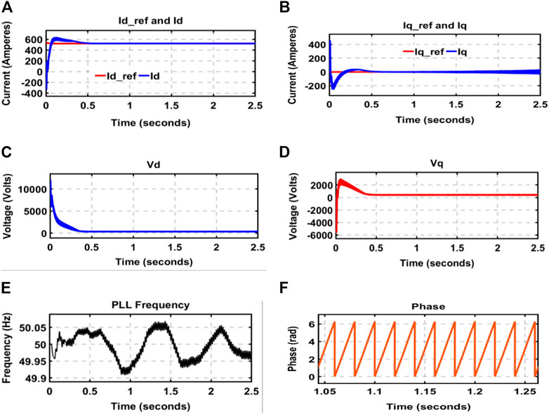
FIGURE 6. (A) Id_ref versus Id, (B) Iq_ref versus Iq, (C) Vd, (D) Vq, (E) Frequency, and (F) Phase.
On the other hand, Figure 6B provides the comparison of the current in the q axis (Iq) and the reference current (Iq_ref). The error resulting from both currents generates the voltage Vq. The steady-state values of Iq and Iq_ref are equal to zero. Before reaching its steady-state, the Iq signal exhibits undershoot and overshoot of 1.956% and 5.833%, respectively.
The voltages in the dq0 frame (Vd and Vq) in Figures 6C,D are used to produce the modulation signal driving the inverter switches. Vd’s steady-state value is 356.5 V (Figure 6C), while Vq’s steady-state value is 415.7 V. The Vd signal displays no undershoot or overshoot, while the Vq signal shows an overshoot of 21.327% and an undershoot of 7.217%.
5.2 Frequency and phase
The PLL tracks the frequency and phase, which also include an inner frequency oscillator. The inner oscillator is modified through the control scheme to keep the phase difference equal to zero. Figure 6E depicts the PLL frequency, which is also the system’s frequency. This frequency varies between 49.9 Hz and 50.05 Hz as the steady-state frequency variation in most power networks is 50 Hz ± 5%.
The PLL assesses the voltage and phase of the grid employed to synchronize the current control in the dq0 frame. A proper phase angle (Figure 6F) to synchronize the PV- FC inverter to the grid is produced by the designed PLL control parameters.
5.3 Inverter response
The inverter is required to deliver a suitable voltage to the grid. The voltage level must be adjusted, paying little heed to the control and load proprieties. It converts the DC voltage to an AC voltage within a line-to-line value range of −1400 V and +1400 V (see Figure 7), as well as the RMS value of 938 V. The AC voltage corresponds to the voltage at the inverter output terminals, with harmonics from the inverter switching. The peak-to-peak voltage is around 2800 V.
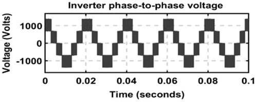
FIGURE 7. Inverter output voltage.
An LCL filter links the grid and the inverter to ensure the generation of no harmonics during inverter switching. Figures 8A,B show the measured THD of the voltage and current at the outputs of the LCL filter. Their corresponding values are 0.32% for the voltage and 0.33% for the current, which comply with the grid connection standards. Figure 8C shows the phase-to-phase voltage while and Figure 8D depicts the LCL filter output current. The magnitude of the voltage is almost 415 V (Figure 8C), whereas the current is approximately 371.9 A (Figure 8D). The voltage waves undershoot and overshoot are evaluated as 19.89% and 0.25%, respectively. While for the current, they are 0.402% and 1.988% for the overshoot and undershoot, respectively.
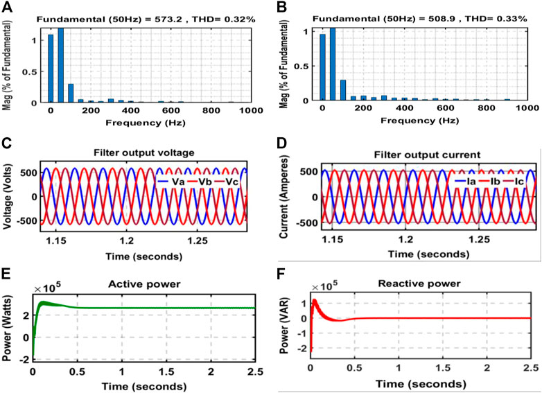
FIGURE 8. (A) Voltage THD, (B) Current THD, (C) Inverter output voltage, (D) Inverter current, (E) Active power, and (F) Reactive power.
The PV- FC active and reactive power curves are depicted in Figures 8E,F, respectively. The active power is about 265 kW, whereas the reactive power is zero.
An overshoot of 31.25% was found I the active power between t = 0 and t = 0.5 s, while the undershoot is 15.538%. The reactive power signal, on the other hand, exhibits overshoot and undershoot of 37.733% and 1.861%, respectively.
5.4 Operating scenarios
The performance of the proposed system was evaluated using two operation scenarios based on the load value. In the first operating scenario, a load value higher than the PV- FC power was used, while the other scenario used a load value less than the PV- FC power. These scenarios evaluate the grid and the load active and reactive power.
5.4.1 Scenario one
This scenario considers a 365 kW load supplied from the output terminals of the grid-tied PV- FC inverter. Since the power from the hybrid PV- FC is lesser than the load requirement, the deficit is imported from the grid. As the inverter has an efficiency of 88%, only about 265 kW was received by the load, with up to 100 kW coming from the grid to fully meet the load demand. The evaluation of the active and reactive power waves was done at the load terminals as shown in Figures 9A,B. The active power’s value is roughly 365 kW, while the reactive power value is 0. The overshoot and undershoot values of 32.222% and 13.783% were observed in the active power The reactive power, on the other hand, does not show an overshoot or undershoot.
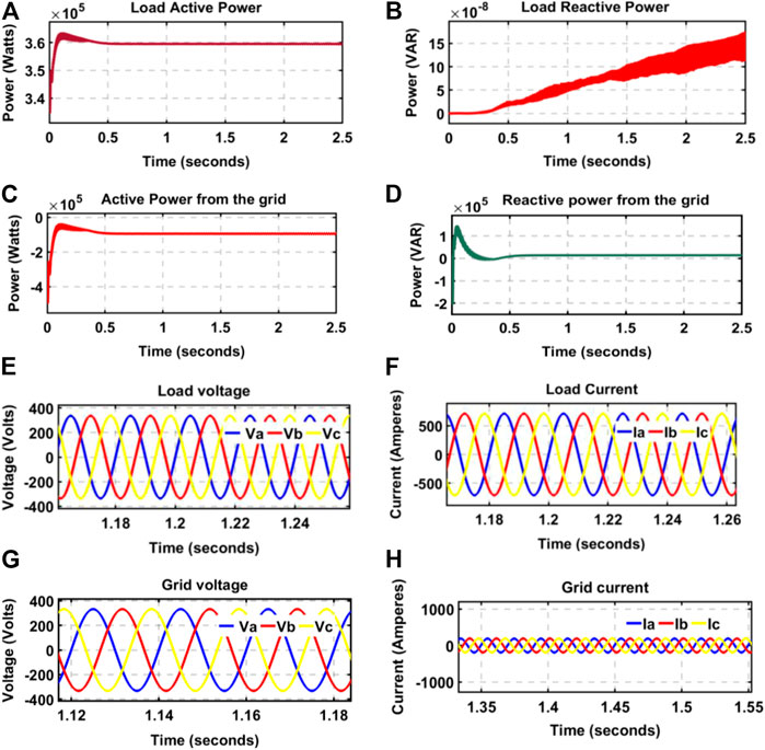
FIGURE 9. (A) Load active power, (B) Load reactive power, (C) Grid active power, (D) Grid reactive power, (E) Load voltage, (F) Load current, (G) Grid voltage, and (H) Grid current.
The grid-sourced active and reactive power is depicted in Figures 9C,D. The grid provides roughly 94.42 kW, while the PV- FC supplies the rest of the power demand. The reactive power at the connection point between the grid and the PV- FC inverter is approximately 15,330 VAR. The active power curve exhibits an overshoot of 28.12%, while the undershoot is 12.207%. Contrarily, an overshoot of 35.115% was noted in the reactive power while the undershoot was 1.915%. Figure 9E showed the phase-to-neutral voltage at the filter’s outputs while Figure 9F displayed the phase-to-neutral current at the output of the filter. These voltages are sinewaves of 237.8 V, and the currents are around 504.7 A. The voltage recorded an overshoot value of 0.397% and an undershoot value of 1.986%, while the overshoot value of the current was 0.397% and 1.986% undershoot value. Figures 9G,H depict the grid phase-to-neutral voltage and the current per phase; their RMS values are 237.8 V and 133.9 A, respectively. The undershoot was 1.987% while the overshoot value was 0.391%. For the current signal, the overshoot value was 0.246% while the undershoot value was 1.987%.
5.4.2 Scenario two
The hybrid PV- FC unit produces sufficient power to meet the load; then, the excess power is transferred to the grid. The active and reactive power fed to the load are depicted in Figures 10A,B. Notably, the value of the active power is 67.05 kW, while that of the reactive power is 8.094e-9 VAR. The signal exhibits 32.955% overshoot between 0 and 0.5 s, while the undershoot is 16.319%. Contrarily, the reactive power recorded an overshoot value of 11.399% and an undershoot value of 5.081%.
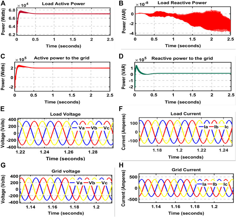
FIGURE 10. (A) Load active power, (B) Load reactive power, (C) Grid active power, (D) Grid reactive power, (E) Load voltage, (F) Load current, (G) Grid voltage, and (H) Grid current.
Figures 10C,D displayed the active and reactive power waves fed to the grid. The grid imports an active power of 198 kW, and the reactive power is 14,710 VAR. The active power signal recorded an overshoot value of 28.723% while the undershoot value was 10.974%. For the reactive power, the overshoot value is 33.865% while the undershoot value is 1.955%. The phase-to-neutral voltage and the current consumed by the load are depicted in Figures 10E,F; the waves are sine waves. The voltages’ RMS is 243 V, while the current in each phase is 91.84 A. The waves had an overshoot value of 0.403% and an undershoot value of 1.989%. The overshoot and undershoot of the currents, on the other hand, are 0.403% and 1.989%, respectively.
The voltages and currents from the grid side are shown in Figures 10G,H. Their RMS values are 243.3 V and 277.5 A, respectively, for the line-to-line voltage and the current. The voltage recorded an overshoot value of 0.4% and an undershoot value of 1.98%. For the current, the values of the overshoot and undershoot are 2.352% and 1.983%, respectively.
5.5 Discussion
The essential concern in making distributed generation resources as entities of modern power systems is the power quality problems, as poor power quality may result in disturbance into the grid in addition to critical financial losses. Helpless force quality can cause framework aggravation and critical financial misfortunes. On-grid distributed generation resources must satisfy grid requirements and other standards regulating their functioning of these entities. One parameter used in power quality assessment is the THD. The THD for both currents and voltages that must not be exceeded by an on-grid distributed generation resource based on the current and voltage levels has been established by the IEC and IEEE guidelines. For instance, voltages in the range of 1–68 kV must have voltage THD below 5%, and for current >1000 A, the current THD must be within 20%. The THD achieved in this investigation has been analyzed against past studies as presented in Table 7. As stated in a previous section, fewer studies focus on the PQ open-loop control scheme; (Vu et al., 2012); introduced a PQ-based approach to evaluate the performance of a PV array interfaced with an active shunt filter. The PV supplied a nonlinear load and injected the excess into a grid.
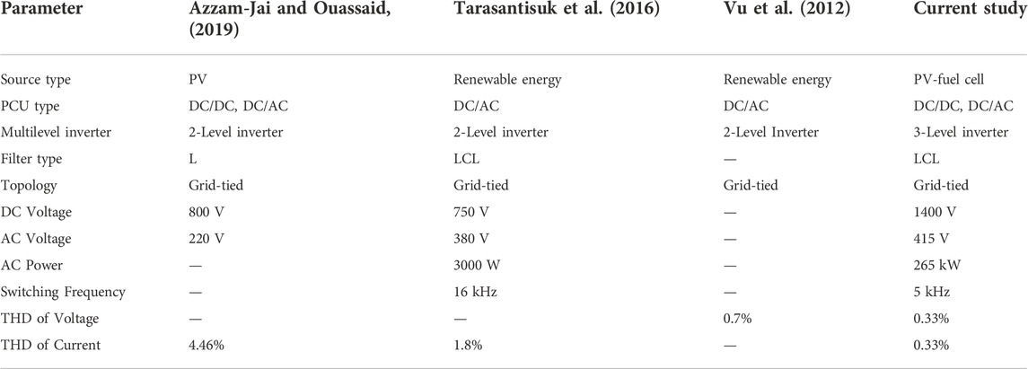
TABLE 7. Comparing study against some related research in literature.
The proposed scheme led to a current harmonic distortion of 4.46%, complying with the IEEE- 519 standards. The study by (Tarasantisuk et al., 2016) proposed a scheme for the control of the active and reactive power of a 3-phase grid-linked inverter based on the use of a proportional resonant control approach. In this set up, the regulation of the active and reactive powers was achieved using current-loop on stationary reference frames. The proposed method was assessed and a current harmonic distortion of 1.8% was achieved. (Vu et al., 2012). introduced a reactive and active power control scheme for a voltage source inverter. A decoupled control technique was implemented based on the inverter current. It was demonstrated that the power control could be applied from renewable energy systems power factor and power quality improvement. Considered to investigations mentioned-above, this study results show a better current harmonic distortion of 0.33%.
6 Conclusion
The connection of distributed energy resources into utility grids requires power converters to condition the power generated and ensure power quality. The grid-tied power converter must achieve high efficiency and low injected current harmonic while regulating the power exported to the grid. Therefore, the power converter control approach plays a vital role in their performance. This study aimed to evaluate the performance of a centralized one-stage grid-connected three-level diode clamped inverter linked to a PV- FC unit. The inverter was operated using an active and reactive open-loop power control system; the achieve current harmonic distortion in the system was below 5%. Apart from the grid, the system is also comprised of a 150 kW/1400 V 150 kW/700 V FC, a 265 kW multilevel inverter operating at a rated voltage of 415 V, and an LCL filter. Two operating scenarios were selected to assess the system’s responses further. In scenario one, a local load of 509.2 kW was supplied from the PV- FC inverter. The load also received the grid’s power to meet the demand as the PV- FC inverter could provide only 265 kW. Whereas in the other scenario, the PV- FC unit provided power to supply a local load while transporting the surplus to the grid. The result analysis revealed the developed model’s good performance with a current harmonic distortion of 0.33%.
Data availability statement
The original contributions presented in the study are included in the article/Supplementary Material, further inquiries can be directed to the corresponding authors.
Author contributions
Conceptualization, MM and KH; methodology, DL; validation, KH, YB, and MS; formal analysis, DL; investigation, MK and MS; data curation, MM, YB, and KH; writing—original draft preparation, MM and DL; writing—review and editing, MS, KH, and YB; supervision, MS and MK; project administration, YB, KH, DL, and MS; funding acquisition, YB. All authors have read and agreed to the published version of the manuscript.
Acknowledgments
The authors thank Ministry of Higher Education Malaysia for the Fundamental Research Grant Scheme (FRGS) awarded for the project (FRGS/1/2020/TK0/UNIMAS/03/4). The authors also acknowledge Universiti Malaysia Sarawak for the financial support of this project.
Conflict of interest
The authors declare that the research was conducted in the absence of any commercial or financial relationships that could be construed as a potential conflict of interest.
Publisher’s note
All claims expressed in this article are solely those of the authors and do not necessarily represent those of their affiliated organizations, or those of the publisher, the editors and the reviewers. Any product that may be evaluated in this article, or claim that may be made by its manufacturer, is not guaranteed or endorsed by the publisher.
References
Ali, Z., Christo, N., Hadjidemetriou, L., Kyriakides, E., and Yang, Y. (2018). Three-phase phase-locked loop synchronization algorithms for grid-connected renewable energy systems : A review. Renew. Sustain. Energy Rev. 90, 434–452. doi:10.1016/j.rser.2018.03.086
Azzam-Jai, A., and Ouassaid, M. (2019). “Adaptive adaline neural PQ strategy-based multipurpose PV interfaced shunt active power filter,” in 2019 8th International Conference on Systems and Control, ICSC 2019, Marrakesh, Morocco, 23-25 October 2019 (IEEE), 71–76. doi:10.1109/ICSC47195.2019.8950643
Buau, X., Wang, X., Pan, D., Yang, D., Li, W., and Bao, C. (2018). Control techniques for LCL-type grid- connected inverters. Singapore: Springer, 319. doi:10.1007/978-981-10-4277-5
Çelik, Ö., Teke, A., and Tan, A. (2018). Overview of micro-inverters as A challenging Technology in photovoltaic applications. Renew. Sustain. Energy Rev. 82, 3191–3206. doi:10.1016/j.rser.2017.10.024
Chaturvedi, P., Jain, S., and Agrawal, P. (2008). “Modeling, simulation and analysis of three-level neutral point clamped inverter using Matlab/Simulink/power system blockset,” in 2005 International Conference on Electrical Machines and Systems, Nanjing, China, 27-29 September 2005, 1223–1227. doi:10.1109/icems.2005.202742
Chen, P. Y., Yu, K. N., Yau, H. T., Li, J. T., and Liao, C. K. (2017). A novel variable step size fractional order incremental conductance algorithm to maximize power tracking of fuel cells. Appl. Math. Model. 45, 1067–1075. doi:10.1016/j.apm.2017.01.026
Chilipi, R., Al Sayari, N., Al Hosani, K., and Beig, A. R. (2016). Control scheme for grid-tied distributed generation inverter under unbalanced and distorted utility conditions with power quality ancillary services. IET Renew. Power Gener. 10, 140–149. doi:10.1049/iet-rpg.2015.0095
Das Gupta, T., Kumar, D., and Chaudhary, K. (2017). “Modelling and analysis of grid-tied fuel cell system with synchronous reference frame control,” in 2017 4th Int. Conf. Power, Control Embed. Syst. ICPCES 2017, Allahabad, India, 09-11 March 2017, 1–6. doi:10.1109/ICPCES.2017.8117665
Elbaset, A. A., Hassan, M. S., and Ali, H. (2016). “Performance analysis of grid-connected PV system,” in Eighteenth International Middle East Power Systems Conference, Cairo, Egypt, 27-29 December 2016 (IEEE). doi:10.1109/MEPCON.2016.7836965
Gao, F., Li, D., Loh, P. C., Tang, Y., and Wang, P. (2009). “Indirect DC-link voltage control of two-stage single-phase PV inverter,” in IEEE Energy Conversion Congress and Exposition, ECCE 2009, San Jose, CA, USA, 20-24 September 2009, 1166–1172. doi:10.1109/ECCE.2009.5316399
Hakimi, S. M., and Hajizadeh, A. (2018). Integration of photovoltaic power units to power distribution system through modular multilevel converter. Energies 11, 2753. doi:10.3390/en11102753
Hamad, K. Ben, Luta, D. N., and Raji, A. K. (2021). A grid-tied fuel cell multilevel inverter with low harmonic distortions. Energies 14, 688. doi:10.3390/en14030688
Hamad, K. B., and Luta, D. N. (2021). “Pq open-loop control of a grid-tied inverter interfacing a large-scale fuel cell stack,” in AIUE Proceedings of the 18th Industrial and Commercial Use of Energy Conference 2020, November 23, 2020. Available at SSRN: https://ssrn.com/abstract=3735393.
Hornik, T., and Zhong, Q. C. (2012). Control of power inverters in renewable energy and smart grid integration. John Wiley & Sons.
Islam, M., and Mekhilef, S. (2014). An improved transformerless grid-connected photovoltaic inverter with reduced leakage current. Energy Convers. Manag. 88, 854–862. doi:10.1016/j.enconman.2014.09.014
Kantar, E., Usluer, S. N., and Hava, A. M. (2014). “Design and performance analysis of a grid connected PWM-VSI system,” in 2013 8th International Conference on Electrical and Electronics Engineering (ELECO), Bursa, Turkey, 28-30 November 2013, 157–161. doi:10.1109/eleco.2013.6713823
Keawthai, S., and Po-Ngam, S. (2015). “Simplified active power and reactive power control with MPPT and islanding detection for three-phase grid-connected photovoltaic inverters,” in ECTI-CON 2015 - 2015 12th International Conference on Electrical Engineering/Electronics, Computer, Telecommunications and Information Technology, Hua Hin, Thailand, 24-27 June 2015 (IEEE), 8–13. doi:10.1109/ECTICon.2015.7207035
Khan, I., Zeb, K., Din, W. U., Islam, S. U., Ishfaq, M., Hussain, S., et al. (2019). Dynamic modeling and robust controllers design for doubly fed induction generator-based wind turbines under unbalanced grid fault conditions. Energies 12, 454–523. doi:10.3390/en12030454
Khan, M. Y. A., Liu, H., Yang, Z., and Yuan, X. (2020). A comprehensive review on grid connected photovoltaic inverters, their modulation techniques, and control strategies. Energies 13, 4185. doi:10.3390/en13164185
Lai, Ji. S., and Ellis, M. W. (2017). Fuel cell power systems and applications. Proc. IEEE 105, 2166–2190. doi:10.1109/JPROC.2017.2723561
Lee, K.-B., and Lee, J.-S. (2017). Reliability improvement Technology for power converters. Singapore: Springer. doi:10.1007/978-981-10-4992-7
Liu, Z., Liu, J., and Zhao, Y. (2014). A unified control strategy for three-phase inverter in distributed generation. IEEE Trans. Power Electron. 29, 1176–1191. doi:10.1109/TPEL.2013.2262078
Mahlooji, M. H., Mohammadi, H. R., and Rahimi, M. (2018). A review on modeling and control of grid-connected photovoltaic inverters with LCL filter. Renew. Sustain. Energy Rev. 81, 563–578. doi:10.1016/j.rser.2017.08.002
Mancilla-David, F., Arancibia, A., Riganti-Fulginei, F., Muljadi, E., and Cerroni, M. (2012). “A maximum power point tracker variable-dc-link three-phase inverter for grid-connected PV panels,” in IEEE PES Innovative Smart Grid Technologies Conference Europe, Berlin, Germany, 14-17 October 2012 (IEEE), 1–7. doi:10.1109/ISGTEurope.2012.6465892
Marx, N., Boulon, L., Gustin, F., Hissel, D., and Agbossou, K. (2014). A review of multi-stack and modular fuel cell systems: Interests, application areas and on-going research activities. Int. J. Hydrogen Energy 39, 12101–12111. doi:10.1016/j.ijhydene.2014.05.187
Miret, J., Camacho, A., Castilla, M., De Vicuna, L. G., and Matas, J. (2013). Control scheme with voltage support capability for distributed generation inverters under voltage sags. IEEE Trans. Power Electron. 28, 5252–5262. doi:10.1109/TPEL.2013.2246190
Modeling, G. P. V. S. (2016). Sliding-mode control of PWM dual inverter-based. IEEE J. Emerg. Sel. Top. power Electron. 04, 435–444.
Ouchen, S., Betka, A., Abdeddaim, S., and Menadi, A. (2016). Fuzzy-predictive direct power control implementation of a grid connected photovoltaic system, associated with an active power filter. Energy Convers. Manag. 122, 515–525. doi:10.1016/j.enconman.2016.06.018
Raju, J., and Tharun Kumar, B. (2017). “Optimized maximum power point tracking technique for the simulation of photovoltaic system sourced for higher output power,” in Proceedings of IEEE International Conference on Innovations in Electrical, Electronics, Instrumentation and Media Technology, ICIEEIMT 2017, Coimbatore, India, 03-04 February 2017 (IEEE), 225–228. doi:10.1109/ICIEEIMT.2017.8116841
Reznik, A., Simoes, M. G., Al-Durra, A., and Muyeen, S. M. (2014). LCL Filter design and performance analysis for grid-interconnected systems. IEEE Trans. Ind. Appl. 50, 1225–1232. doi:10.1109/TIA.2013.2274612
Ro, K., and Rahman, S. (1997). Two-loop controller for maximizing performance of a grid-connected photovoltaic-fuel cell hybrid power plant. IEEE Power Eng. Rev. 17, 30.
Salilih, E. M., and Birhane, Y. T. (2019). Modeling and analysis of photo-voltaic solar panel under constant electric load. J. Renew. Energy 2019, 1–10. doi:10.1155/2019/9639480
Satpathy, S., Padhee, S., Bhuyan, K. C., and Ingale, G. B. (2016). “Mathematical modelling and voltage control of fuel cell,” in 2016 International Conference on Energy Efficient Technologies for Sustainability (ICEETS), Nagercoil, India, 07-08 April 2016 (IEEE), 781–786. doi:10.1109/ICEETS.2016.7583853
Shriwastava, R. G., Daigavane, M. B., and Daigavane, P. M. (2016). Simulation analysis of three level diode clamped multilevel inverter fed PMSM drive using carrier based space vector pulse width modulation (CB-svpwm). Procedia Comput. Sci. 79, 616–623. doi:10.1016/j.procs.2016.03.078
Tan, K. T., So, P. L., Chu, Y. C., and Chen, M. Z. Q. (2013). Coordinated control and energy management of distributed generation inverters in a microgrid. IEEE Trans. Power Deliv. 28, 704–713. doi:10.1109/TPWRD.2013.2242495
Tarasantisuk, C., Suyata, T., Tarateeraseth, V., and Witheephanich, K. (2016). “Active and reactive power control for three-phase grid inverters with proportional resonant control strategies,” in 2016 13th International Conference on Electrical Engineering/Electronics, Computer, Telecommunications and Information Technology (ECTI-CON), Chiang Mai, Thailand, 28 June 2016 - 01 July 2016 (IEEE), 1–6. doi:10.1109/ECTICon.2016.7561379
Teodorescu, R., Liserre, M., and Rodriguez, P. (2011). Grid converters for photovoltaic and wind power systems. New Delhi: IEEE-WILEY.
Tesfahunegn, S. G. (2012). Fuel cell assisted photovoltaic power systems. PhD thesis. NTNU-Trondheim.
Timbus, A., Teodorescu, R., Blaabjerg, F., and Liserre, M. (2005). “Synchronization methods for three phase distributed power generation systems. An overview and evaluation,” in IEEE 36th Power Electronics Specialists Conference, Dresden, Germany, 16-16 June 2005 (IEEE). doi:10.1109/PESC.2005.1581980
Vu, H. G., Yahoui, H., Chorot, T., and Hammouri, H. (2012). “Control active and reactive power of voltage source inverter (VSI),” in 2012 2nd International Symposium On Environment Friendly Energies And Applications, Newcastle Upon Tyne, UK, 25-27 June 2012 (IEEE), 308–311. doi:10.1109/EFEA.2012.6294057
Wu, X., Tan, G., Ye, Z., Yao, G., Liu, Z., and Liu, G. (2018). Virtual-space-vector PWM for a three-level neutral-point-clamped inverter with unbalanced DC-links. IEEE Trans. Power Electron. 33, 2630–2642. doi:10.1109/TPEL.2017.2692272
Xiao, W., Moursi, M. S. E., Khan, O., and Infield, D. (2016). Review of grid-tied converter topologies used in photovoltaic systems. IET Renew. Power Gener. 10, 1543–1551. doi:10.1049/iet-rpg.2015.0521
Yu, X., Starke, M., Tolbert, L., and Ozpineci, B. (2007). Fuel cell power conditioning for electric power applications: A summary. IET Electr. Power Appl. 1, 643–656. doi:10.1049/iet-epa:20060386
Keywords: fuel cell, microgrid, photovoltaic system, PQ open-control, harmonic
Citation: Muftah MG, Salem M, Buswig YM, Hamad KB, Luta DN and Kamarol M (2022) A grid-tied PV-fuel cell multilevel inverter under PQ open-loop control scheme. Front. Energy Res. 10:968371. doi: 10.3389/fenrg.2022.968371
Received: 13 June 2022; Accepted: 25 November 2022;
Published: 08 December 2022.
Edited by:
Bhavnesh Kumar, Netaji Subhas University of Technology, IndiaReviewed by:
Karthik Balasubramanian, McMaster University, CanadaArjun Tyagi, Netaji Subhas University of Technology, India
Himanshu Grover, Indian Institute of Technology Delhi, India
Copyright © 2022 Muftah, Salem, Buswig, Hamad, Luta and Kamarol. This is an open-access article distributed under the terms of the Creative Commons Attribution License (CC BY). The use, distribution or reproduction in other forums is permitted, provided the original author(s) and the copyright owner(s) are credited and that the original publication in this journal is cited, in accordance with accepted academic practice. No use, distribution or reproduction is permitted which does not comply with these terms.
*Correspondence: Mohamed Salem, c2FsZW1tQHVzbS5teQ==; Yonis M. Buswig, YnlvbmlzQHVuaW1hcy5teQ==