 Zhihua Zhang1,2*
- 1Department of Power Grid Information and Control Engineering, Xi’an University of Technology, Xi’an, China
- 2State Grid Shaanxi Electric Power Research Institute, Xi’an, China
In order to identify the fault nature when phase-to-phase short circuit fault occurs in distribution lines and realize adaptive reclosing of distribution lines more accurately, a fault identification scheme using an inverter-based power electronic technology and power supply from stored energy capacitor is proposed in this paper. The corresponding device is designed which is composed of rectification, energy storage and inverters. Supplied by power from high voltage side of distribution transformers, three-phase symmetrical characteristic frequency voltage signals are injected into the de-energized network. Then the fault type can be determined according to the positive sequence resistance of the equivalent network under different fault properties. In this paper, the overall structure diagram of the system scheme is proposed, and the operation sequence of the system is analyzed. The control strategy is designed to maintain the stability of the output voltage. The feasibility and rationality of the proposed scheme are verified by theoretical analysis and simulation results.
1 Introduction
Auto reclosing technology is widely used in power system because it can obviously shorten the outage time and improve the reliability of power supply. In recent years, with the increasing proportion of cables in the distribution network and the emergence of a large number of hybrid lines comprising overhead lines and cables, the success rate of reclosing has been significantly reduced. Reclosing a line with permanent faults will not only result in reclosing failure and cause damage to the circuit breaker, but also have a serious impact on the loads equipment, and deteriorate the power quality (Xunhua et al., 2017; Jiaxing et al., 2018; Shubham et al., 2021). Therefore, many power companies have specified that as long as the feeder contains cables, the automatic reclosing facilities will be disabled, which seriously reduces the supply reliability of the power systems. Therefore, it is necessary to study the accurate identification of fault property (instantaneous fault or permanent fault), which has theoretical and practical significance for improving the reclosing success rate and improving the power supply reliability of distribution network.
The concept of adaptive reclosing was put forward in the 1980s. However, the research on adaptive reclosing mostly focuses on the adaptive reclosing technology of transmission lines. The basic idea is to judge the fault type by the electrical information of lines after faults (Le Blond and Aggarwal, 2012; Radojevic et al., 2013; Basu and George, 2014). There is little research on the adaptive reclosing technology of distribution lines. However, the structure, parameter characteristics and protection action mode of distribution lines are very different from those of transmission lines. The adaptive reclosing strategies of transmission lines have great limitations in the application to distribution lines for the unavailability of electrical characteristic information after distribution line tripping. Therefore, it is necessary to study the adaptive reclosing technology of distribution lines.
At present, distribution line impedance detection method is one of the automatic reclosing technologies, and it can be mainly divided into passive detection and active detection. For the passive detection method, no extra signal is needed but its detection accuracy will be affected by other grid-connected equipment in the line (Cobreces et al., 2009; Ghanem et al., 2017). For the active detection method, it is needed to inject disturbance signal into the distribution line. The most common way is to inject non-integer multiple harmonics signal into the line and extract the corresponding harmonic response signal to calculate the impedance. Reference (Xun et al., 2011) uses a special high-voltage circuit breaker to directly connect the distribution line that has been cut off to the upstream system power supply. Through the generated current amplitude, it can be judged whether there is a fault in the line. Reference (Zhang et al., 2018) uses the energy storage and discharge information of shunt capacitors in distribution lines to identify the phase-phase resistance to determine whether the fault disappears. At present, power electronics technology is being applied to automatic reclosing. Power electronic equipment has fast response speed and high controllability, which is conducive to fault ride-through, clearance, isolation and recovery. Meanwhile, it provides effective fault characteristics for fault identification and improves the speed and reliability of protection. Reference (Anwar et al., 2014) uses inverter with energy storage power supply to realize soft reclosing. In Reference (Zhu and Lv, 2019), an inverter is connected to the low-voltage side of the distribution transformer, and the instantaneous voltage and current is analyzed to obtain the frequency-domain characteristics of the outage line. With the help of the linear relationship between disturbance excitation and response, the equivalent harmonic impedance of the outage line is measured in real time to identify its internal structure and determine whether the circuit breaker is reclosed. However, there are the following problems: injecting high voltage source at the low-voltage side might threaten personal safety, and the cost is high with the additional energy storage equipment to provide energy for the system.
In this paper, a fault identification scheme using an inverter-based power electronics technology and power supply from stored energy capacitor is proposed. A fault diagnosis device based on power electronics technology is proposed. The fault identification device including the inverter output the three-phase symmetrical voltage signal applied to the de-energized feeder. The system operation sequence of the proposed scheme is analyzed and the fault detection criterion is given. The advantage of the scheme proposed in this paper is that no additional power supply is required, the power is directly taken from the energy storage capacitor which stores energy from the high voltage side of distribution transformers. Finally, the simulation cases are given to verify the feasibility of the proposed strategy.
2 System scheme design and time sequence analysis
Figure1 shows the illustration for the proposed scheme including the fault nature identification device. As shown in Figure 1, the fault nature identification device includes rectifier module, relays inverter moduleE, and boost transformer. Where CB is the circuit breaker of distribution line, C is energy storage capacitor, S1 is DC relay, and S2 is AC relay, the ratio of the boost transformer ratio is 0.4 kV/10 kV, and the DC voltage is 310 V.

FIGURE1. Overall structure of the fault identification scheme using power electronics technology.
When a short-circuit fault occurs in the feeder, the Feeder Terminal Unit (FTU) completes fault clearance and fault phase selection. The fault phase selection signal is sent to the fault nature identification device. The fault nature signal fed back by the device determines whether CB is to reclose. The function of the fault nature identification device is to generate three-phase voltage signals of characteristic frequency, inject the signal into the disconnected network, and then collect the secondary side voltage and current information of the boost transformer, calculate the equivalent network impedance of the disconnected network, and then judge the fault nature.
The device uses the power electronic conversion technology to generate the three-phase symmetrical voltage of the characteristic frequency which is injected into the de-energized network. The resistance of the equivalent network is calculated. And then the fault nature identification result is obtained and transmitted to FTU. The automatic reclosing of the distribution network feeder is realized.
The sequence of system operation is shown in Figure 2, the fault identification device operates between t2 and t5. The specific implementation process is described as follows.
1) Before t0 time: The distribution line is in its normal condition and S2 is disconnected. The fault nature identification device continuously detects the capacitor voltage udc. When it is lower than 300 V, S1 is closed to charge the capacitor, otherwise, S1 is disconnected. The capacitor is charged from the secondary side of PT through rectifier;
2) t0 time: A fault has occurred on the distribution line;
3) t1 time: After a short delay time, the circuit breaker CB trips, and FTU completes fault clearance and faulted phase selection, and the phase signal of fault is sent to the fault identification device;
4) t2 time: S1 is disconnected and S2 is closed;
5) t3 time: The positive sequence and the negative sequence of the voltage and current control for the inverter in the fault identification device work, and the inverter soft starts until the output voltage peak reaches the set value;
6) t4 time: Three-phase symmetrical voltage signal with characteristic frequency is outputted from the fault identification device, and the signal is injected into the disconnected distribution line. And then the positive sequence resistance of distribution line is calculated;
7) t5 time: The fault nature is identified according to the resistance setting threshold, and the identified fault nature is sent to FTU;
8) t6 time: FTU executes reclosing command or line reclosing locking action according to the fault nature discrimination result.

FIGURE 2. Sequence diagram of system scheme.
3 Fault property identification criteria and setting values
3.1 Characteristics of fault impedance under different fault properties
Take the short circuit fault between phase A and phase B as an example, the equivalent network is shown in Figure 3. Where

FIGURE 3. Equivalent network for inter phase short circuit fault analysis.
3.1.1 Instantaneous fault impedance characteristics
According to Figure 3A, the equivalent impedance of interphase short circuit fault between phase A and phase B can be obtained, as shown in 1.
The equivalent impedance under instantaneous fault can be obtained from Figure 3A, as shown in Eq. 2.
The real part
It can be seen from Eq. 3 that for instantaneous faults, the resistance part of the equivalent impedance of the distribution line identified from the high voltage side of the boost transformer consists of the resistance of the distribution line and the load resistance under the injection signal frequency.
3.1.2 Permanent fault impedance characteristics
From Figure 3B, considering
It can be seen from Eq. 5 that for permanent faults, the resistance part of the equivalent impedance of the distribution line identified from the high voltage side of the boost transformer consists of the resistance of the distribution line and the fault transition resistance under the injection signal frequency.
3.2 Discrimination setting value of positive sequence resistance of fault impedance.
Common cable line models are YJV-150, YJV-185, YJV-240, and YJV-300 etc. The maximum unit length resistance shall not exceed 0.153 Ω/km. Common overhead line models are LGJ-150, LGJ-185, and LGJ-240 etc., and the maximum resistance per unit length shall not exceed 0.21 Ω/km. Generally, the length of cable line is not more than 5 km, and the length of overhead line is not more than 10 km. So the maximum resistance of cable line is 0.765 Ω, and the maximum resistance of overhead line is 2.1 Ω. The maximum of
The rated amperage of various types of distribution lines is not more than 600 A, that is, the maximum load current of the line is not more than 600 A. The minimum load impedance of the corresponding distribution line is 10 kV/1.732/600A = 9.6 Ω. Considering the load power factor as 0.8, the minimum value of the resistive part of the load impedance is 7.68 Ω. In combination with Eq. 3, it can be obtained that, for instantaneous faults, the resistance part of equivalent impedance of distribution line identified from the high voltage side of boost transformer is not less than 7.98 Ω by comprehensively considering cable and overhead line.
According to the above analysis, the threshold of
4 Scheme of characteristic frequency three-phase symmetrical voltage signal using power electronics technology
The inverter-based power electronics technology is used in the fault identification device. The control strategy of positive and negative sequence signal separation is designed for the inverter to generate the three-phase symmetrical voltage signal with characteristic frequency which is injected into the de-energized line, and then the fault nature is determined by
When an interphase fault occurs in the distribution system, the unbalance degree of the three-phase system is very high. It is very critical to make the three-phase inverter in the fault identification device output a stable three-phase balanced voltage signal with the characteristic frequency. Figure 4 shows the control strategy diagram of the three-phase inverter in the fault identification device. The three-phase voltages uoa, uob and uoc are sampled, and uα, uβ in two-phase static coordinate system can be obtained by Clarke transformation Eq. 6. The voltage positive sequence component uα+, uβ+ and negative sequence component uα−, uβ− in the static coordinate system can be obtained by Eqs 7, 8, where uα' and uβ' lag uα, uβ signal 90° respectively. After the positive sequence component and negative sequence component of the output voltage are separated, the positive sequence and negative sequence voltage and current control double loops are designed and carried out respectively. Then the positive sequence modulation signal urabc+and negative sequence modulation signal urabc− are added and modulated, and then the inverter is driven by the switch driving circuit to generate the stable three-phase symmetrical voltage signal to inject into the disconnected line.
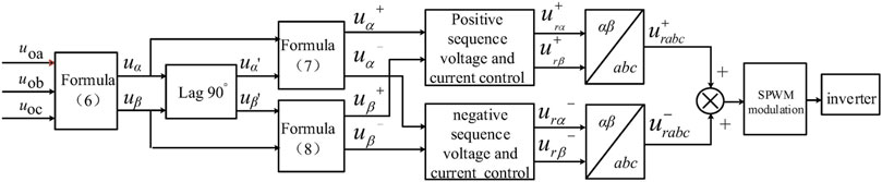
FIGURE 4. Control strategy diagram for the inverter to realize three-phase symmetrical voltage in fault identification scheme.
It is worthy of note that the frequency of the injection three-phase voltage signal should be properly selected. Two main factors considered are as follows: 1) To avoid confusion with conducted interference or coupling interference signals inherent in the distribution system, the frequency should be selected between the Nth and (N+1)th harmonic. 2) If the frequency of the injected characteristic signal is too high, the ground capacitive reactance of the distribution line will be significantly reduced, which may have an adverse impact on the identification of fault nature. Meanwhile, it will increase the speed requirements for signal acquisition and processing. Considering the above two aspects, the injected characteristic signal angular frequency
5 Simulation verification
Based on the MATLAB/Simulink platform, the 10 kV distribution system model and the fault identification device model using power electronic converter are built for simulation verification. The 10 kV distribution system is shown in Figure 5. The system parameters of distribution network are shown in Table 1. The simulation is carried out for overhead Line1 and cable Line3 respectively.

FIGURE 5. 10 kV distribution system.

TABLE 1. System parameters of distribution network.
The fault occurs at 0 s. After the arc suppression of the circuit breaker, the AC relay is closed at 0.06 s, and the inverter soft-starts and becomes stable at 0.08 s. Figure 6 shows the three-phase voltage waveforms output by the three-phase inverter under two fault types. It can be seen that the three-phase voltage is symmetrical.

FIGURE 6. Output characteristic frequency voltage waveforms of three-phase inverter.
In the following, the simulation waveforms of the detected
Case I: Permanent fault in overhead Line1.
According to the permanent fault equivalent network in Figure 3, the positive sequence resistance measured by the fault identification device is independent of the load. Figures 7, 8, 9 respectively show

FIGURE 7. Permanent two-phase short circuit fault at end of Line1.

FIGURE 8. Permanent two-phase short circuit fault at middle of Line1.

FIGURE 9. Permanent two-phase short circuit fault at head of Line1.
It can be seen from Figure 7 that the inverter is put into operation at 0.06 s and reaches stability after soft start at 0.08 s. The effective value of line voltage
Figure 8A and Figure 8B show the line voltage and phase current waveforms respectively in case of faults at the middle of Line1. Figure 9A and Figure 9B show the line voltage and phase current waveforms respectively in case of faults at the head ends of Line. Figure 8C and Figure 9C show the measured values for are 1.693 Ω and 1.139 Ω respectively. Similarly, the theoretical values are 1.69 and 1.138 Ω respectively. The errors between the measured value and the theoretical calculation value for
Figure 10 shows the simulation results of permanent three-phase short circuit fault at end of Line1. Figure 10A, Figure 10B and Figure 10C show the line voltage, phase current and waveforms respectively. It can be known that the value of

FIGURE 10. Permanent three-phase short circuit fault at end of Line1.

TABLE 2.
Case II: Instantaneous fault in overhead Line1.
Figure 11 shows the simulation results of the line voltage waveforms, three-phase current waveforms and the equivalent impedance output by the fault identification device in case of 0.8 (.pu) load. It can be seen from Figure 11 that in the steady state, the effective value of line voltage

FIGURE 11. Instantaneous three-phase short circuit fault at end of Line1 (0.8 pu).
In case of instantaneous fault, the positive sequence resistance value in two-phase short circuit fault is the same with the value in three-phase short circuit.
Table 3 shows

TABLE 3.
Case III: Permanent and instantaneous faults in cable Line3.
Figure 12 shows the simulation results when a permanent short fault occurs at the end of cable Line3. Figure 12A, Figure 12B and Figure 12C show the waveforms of the line voltage, phase current and. Figure 13 shows the simulation results when an instantaneous short fault occurs at the end of cable Line3. Figure 13A, Figure 13B and Figure 13C show the waveforms of the line voltage, phase current and Similarly, through the simulation waveforms of

FIGURE 12. Permanent short circuit fault at end of Line3.

FIGURE 13. Instantaneous short circuit fault at end of Line3.
6 Conclusion
When a distribution line trips due to an interphase fault and the circuit breaker recloses blindly to the line with permanent fault, the distribution line and circuit breaker might be damaged. To improve the success rate of reclosing, this paper proposes an active detection scheme for permanent fault identification using power electronic inverter. The inverter provides a stable three-phase symmetrical voltage signal with a characteristic frequency to the de-energized feeder, and the equivalent impedance of the de-energized line can be obtained by measuring the voltage and current of the feeder. The positive sequence resistance value of the equivalent impedance is used as the criterion, according to which, it can be judged whether the line still experiences fault and then decide whether the circuit breaker should be reclosed. This paper describes the overall scheme of the proposed system, illustrates the operation sequence of the system, establishes the equivalent network structure under instantaneous fault or permanent fault and gives the fault detection criterion, and designs the inverter control strategy of three-phase symmetrical voltage signal of the de-energized line. Simulations performed using MATLAB simulation software show that when two types of faults occur on overhead lines and cable lines, the positive sequence resistance value of the detected equivalent network impedance is consistent with the theoretical calculation, verifying the correctness and effectiveness of the design proposed scheme.
Data availability statement
The original contributions presented in the study are included in the article/supplementary material, further inquiries can be directed to the corresponding author.
Author contributions
Conceptualization, ZZ; methodology, JL; software, BR; validation, YM.
Conflict of interest
The authors declare that the research was conducted in the absence of any commercial or financial relationships that could be construed as a potential conflict of interest.
Publisher’s note
All claims expressed in this article are solely those of the authors and do not necessarily represent those of their affiliated organizations, or those of the publisher, the editors and the reviewers. Any product that may be evaluated in this article, or claim that may be made by its manufacturer, is not guaranteed or endorsed by the publisher.
References
Anwar, A., Zhang, Y., Brice, C. W., and Dougal, R. A. (2014). Soft reclosing of an industrial power network using an inverter-controlled energy-storage system. IEEE Trans. Power Deliv. 29 (3), 1111–1119. doi:10.1109/tpwrd.2013.2292884
Basu, K. P., and George, M. (2014). Maintaining balanced three‐phase load voltage during single‐phase auto‐reclosing in medium voltage distribution lines. IET Gener. Transm. &. Distrib. 8 (5), 798–802. doi:10.1049/iet-gtd.2013.0663
Cobreces, S., Bueno, E. J., Pizarro, D., Rodriguez, F., and Huerta, F. (2009). Grid impedance monitoring system for distributed power generation electronic interfaces. IEEE Trans. Instrum. Meas. 58 (9), 3112–3121. doi:10.1109/tim.2009.2016883
Ghanem, A., Rashed, M., Sumner, M., Elsayes, M. A., and Mansy, I. I. (2017). Grid impedance estimation for islanding detection and adaptive control of converters. IET Power Electron. 10 (11), 1279–1288. doi:10.1049/iet-pel.2016.0780
Jiaxing, N., Baina, H., Zhenzhen, W., and Jie, K. (2018). Algorithm for adaptive single-phase reclosure on shunt-reactor compensated extra high voltage transmission lines considering beat frequency oscillation[J]. IET generation, Transm. distribution 25, 3191–3200.
Le Blond, S. P., and Aggarwal, R. K. (2012). Design of adaptive autoreclosure schemes for 132 kV network with high penetration of wind—Part I: Real-time modeling. IEEE Trans. Power Deliv. 27 (3), 1055–1062. doi:10.1109/tpwrd.2012.2188651
Radojevic, Z., Terzija, V., Preston, G., Padmanabhan, S., and Novosel, D. (2013). Smart overhead lines autoreclosure algorithm based on detailed fault analysis. IEEE Trans. Smart Grid 41 (4), 1829–1838. doi:10.1109/tsg.2013.2260184
Shubham, G., Das, P., and Biswal, M. (2021). Uninterrupted power supply to BESS based microgrid system using adaptive reclosing approach. IET Gener. Transm. Distrib. 15, 1203–1213. doi:10.1049/gtd2.12096
Xun, L., Wilsun, X., and Yunwei, L. (2011). A new technique to detect faults in de-energized distribution feeders-Part I: Scheme and asymmetrical fault detection[J]. IEEE Trans. Power Deliv. 26 (3), 1893–1901.
Xunhua, L., Chun, H., and Yaqun, J. (2017). Adaptive single-phase reclosure scheme for transmission lines with shunt reactors based on current inner product[J], 11, 1770–1776. doi:10.1049/iet-gtd.2016.1553IET generation, Transm. distribution
Zhang, Z. H., Qiao, H., and Shao, W. Q. (2018). Non-fault detection in phase-to-phase faults before reclosing in distribution network. Smart Power[J] 46 (2), 66–71.
Keywords: fault identification, auto reclosing, power electronic technology, phase to phase fault, characteristic frequency signal
Citation: Zhang Z, Liu J, Ren B and Ma Y (2022) Permanent fault identification for distribution network based on characteristic frequency signal injection using power electronic technology. Front. Energy Res. 10:967592. doi: 10.3389/fenrg.2022.967592
Received: 13 June 2022; Accepted: 30 June 2022;
Published: 09 August 2022.
Edited by:
Zaibin Jiao, Xi’an Jiaotong University, ChinaReviewed by:
Guobing Song, Xi’an Jiaotong University, ChinaYanfang Wei, Henan Polytechnic University, China
Xiangxiang Wei, Technical University of Berlin, Germany
Copyright © 2022 Zhang, Liu, Ren and Ma. This is an open-access article distributed under the terms of the Creative Commons Attribution License (CC BY). The use, distribution or reproduction in other forums is permitted, provided the original author(s) and the copyright owner(s) are credited and that the original publication in this journal is cited, in accordance with accepted academic practice. No use, distribution or reproduction is permitted which does not comply with these terms.
*Correspondence: Zhihua Zhang, zzhtsky123@163.com