 Ashish Jaiswal1
 Youcef Belkhier2Subhash Chandra1Anurag Priyadarshi1
 Mohit Bajaj3Mukesh Pushkarna1
 Elmazeg Elgamli4*
 Mokhtar Shouran4
 Salah Kamel5
- 1Department of Electrical Engineering, GLA University Mathura, Mathura, India
- 2Centre for Ocean Energy Research, Maynooth University, Maynooth, Kildare
- 3Department of Electrical Engineering, Graphic Era (Deemed to be University), Dehradun, India
- 4Wolfson Centre for Magnetics, School of Engineering, Cardiff University, Cardiff, United Kingdom
- 5Department of Electrical Engineering, Faculty of Engineering, Aswan University, Aswan, Egypt
Given the greater penetration of wind power, the impact of wind generators on grid electricity reliability imposes additional requirements. One of the most common technologies in wind power generating schemes is the permanent magnet synchronous generator (PMSG) converter. However, the controller calculation is difficult due to the nonlinear dynamical and time-varying characteristics of this type of conversion system. This study develops a unique intelligent controller approach based on the passivity notion that tracks velocity and maintains it functioning at the optimum torque. To address the robustness issues encountered by traditional generator-side converter (MSC) strategies such as proportional-integral (PI), this suggested scheme integrates a passivity-based procedure with a fuzzy logic control (FLC) methodology for a PMSG-based wind power converter. The suggested controller is distinguished by the fact that the nonlinear features are compensated in a damped manner rather than canceled. To achieve the required dynamic, the fuzzy controller is used, which ensures quick convergence and global stability of the closed loop system. The development of the maximum power collected, the lowered fixed gains, and the real-time application of the control method are the primary contributions and novelties. The primary objectives of this project are to manage DC voltage and attain adequate reactive power levels in order to provide dependable and efficient electricity to the grid. The proposed scheme is being used to regulate the MSC, while the grid-side employs a traditional proportional-integral method. The efficiency of the suggested technique is investigated numerically using MATLAB/Simulink software. Furthermore, the processor-in-the-loop (PIL) tests are carried out to demonstrate that the suggested regulator is practically implementable.
Introduction
Sustainable energy source innovations are turning into an expanding option to address the issues of environmental change. One of the most promising types of renewable energy is wind energy. Wind power has been in full industrial growth for some years. Indeed, it has several advantages: first and foremost, it is a non-polluting renewable energy source that helps to improve air quality and the reduction of greenhouse gas emissions. It is also a form of energy that makes use of domestic resources and so helps to energy independence and supply security, its high-power density, and a high potential for electricity generation (Soliman et al., 2021). The role of a wind turbine is to convert the kinetic energy of the wind into electrical energy. Its various elements are designed to maximize this energy conversion. There are several technologies that are used to capture the energy of the wind (vertical axis or horizontal axis), and also, different configurations of a wind turbine system (fixed speed and variable speed). Therefore, wind turbines are considered with variable power generators, connected to the electrical grid. The amount of energy recovered by variable speed wind energy conversion systems (VS-WECS) depends on the accuracy of the maximum power point tracking (MPPT) search and also on the type of generator used. The associated power conversion chains often use a PMSG (Soliman et al., 2021), (Mohammadi et al., 2019). This type of machine allows making it possible to get rid of the problem of the excitation current supply, which is difficult to manage in a conventional synchronous machine (Mohammadi et al., 2019). However, due to unknown modeling inaccuracy, dynamic characteristics, and non-linearities, control system computation for the PMSG remains a difficult task (Wang and Wang, 2020). In the literature, there has been several research studies related to the nonlinear control of PMSG. In the study by Saidi et al. (2019), a tip-speed ratio technique associated with an integral backstepping controller is suggested. A mechanical sensorless control strategy-based nonlinear observer is proposed (Fantino et al., 2016). In the work of Zargham and Mazinan (2019), a super-twisting sliding mode controller is designed. A new direct torque of a fault-tolerant direct-driven PMSG controller is developed (Jlassi and Cardoso, 2019). To achieve direct power control, an optimal voltage vector-based modulated model predictive control is developed in Bigarelli et al. (2020). Further, in the study by Haq et al. (2020), a maximum power extraction-based feed-forward neural network and generalized global sliding mode controller are investigated. Meanwhile, an autonomous PMSG-based wind conversion system is controlled by using a cascade neural networks algorithm (Chandrasekaran et al., 2020). More recently, a nonlinear model predictive control with the fuzzy regulator is proposed in Song et al. (2022a), for the optimization of the energy capture and torque fluctuation of wind turbines. In the study by Song et al. (2022b), a stochastic model predictive yaw control strategy based on intelligent scenario generation is proposed to improve the energy capture efficiency of wind energy converters. A chaos-opposition-enhanced slime mould algorithm to minimize energy cost for the wind turbines on high-altitude sites is developed in Rizk-Allah et al. (2022), the proposed model is established based on rotor radius, rated power, and hub height needed to achieve an optimal design model. However, as stated in Yang et al. (2013), most of such controls are dependent on signals and therefore do not consider the structural properties of the PMSG when building the regulator.
The present article investigates a new control approach based on the passivity notion, a new fuzzy passivity-based control (PBC) to design an optimal controller for the PMSG, which tracks speed and maintains it functioning at the optimal torque. Inherent advantages of the PBC method are that the nonlinear terms are adjusted in a damped manner rather than being eliminated that the assured stability, as well as the promised robustness qualities (Nicklasson et al., 1994), (Belkhier et al., 2022). The study’s major goal is to highlight a hybrid control method for VS-WECS, to enable efficient power integration to the grid and increase the PMSG operational speed.
Several techniques have been reported in the literature based on the passivity control method to improve the performance of the PMSG and increase the efficiency of wind energy conversion systems. A sliding mode strategy (SMC) associated with PBC is adopted in Yang et al. (2018a). However, as the authors point out, the provided coupled PBC-SMC controlling employs over six fixed gains, making it hard to find their ideal settings. A passivity-based linear feedback current control approach is developed for a PMSG in Belkhier and Achour (2020a), where the authors proposed PBC with an orientation of the flux, where the desired current is computed by a PI controller. However, the use of the PI implies fixed gains, which brings a significant sensitivity to disturbances that can affect the functioning of the system. In Subramaniam and Joo (2019), a PBC-SMC and fuzzy controller is proposed. However, the suggested combined strategy’s controller design is complex due to mathematical constraints; passivity-based linear feedback control is explored in Yang et al. (2018b). However, nonlinear properties and the robustness due to parameter changes of the PMSG have not been evaluated. In Belkhier and Achour (2020b), a passivity-based backstepping is proposed. However, due to mathematical limitations, the controller design of the proposed combination method is complicated.
As it was mentioned before, several aspects were neglected by the works carried out. In order to make more improvements and contributions to what was performed. The present work is split into two sections. First, a fuzzy-PBC system is used to ensure that the PMSG receives continuous power from the wind source, increase the PMSG operational speed, and rectify non-linearities, external disturbances, and parametric fluctuations in the PMSG. The second is devoted to applying the classical PI control to regulating the grid-side power and voltage. A special focus is given to the control of the PMSG, by synthesizing the new suggested control scheme while considering the complete dynamic of the PMSG. In addition, the resilience over parameter variations has received considerable consideration. Also, experimental testing of the investigated strategy is conducted using a DSP card, and the results show clearly that the present system is applicable practically.
The contribution and novelty of the present article are summarized as follows:
• A novel control technique based on hybrid fuzzy-PBC for optimum efficiency of the PMSG is presented to ensure a quick convergence of the locked system and energy extraction.
• By simulating the unstructured dynamics of the PMSG, the fuzzy manager is employed for gain adjustment, which meets the requirements produced by incorrect variables to calculate the appropriate dynamics and considerably enhances the resilience of the system.
• Numerous numerical studies are conducted to show how resilient the suggested technique is to parameter changes and outside disruptions. In addition, analytical proof of the closed-stability loop’s and exponential convergence has been provided.
• The novelty of the proposed control lies in its structure, which is really very simple and contains only one fixed gain, which is the damping gain of the control, which makes it particularly robust and increases resilience and global stability, as demonstrated in the results section.
• Experimental validation of the proposed control schemes is conducted using processor-in-the loop (PIL) and the results show clearly that the present system is applicable practically.
The current article is arranged in the following manner: Introduction establishes the system description. The proposed strategy calculation is discussed in Introduction. Concerning Introduction, grid-side converter (GSC) voltage and management is presented. In Introduction, simulation experimental results are exposed. Finally, Introduction finishes with the main findings and recommendations for future research.
System description
Figure 1 shows the setup of the MATLAB/Simulink-based wind energy converter, which includes a wind turbine, PMSG, AC-DC-AC converter, and main electrical network.
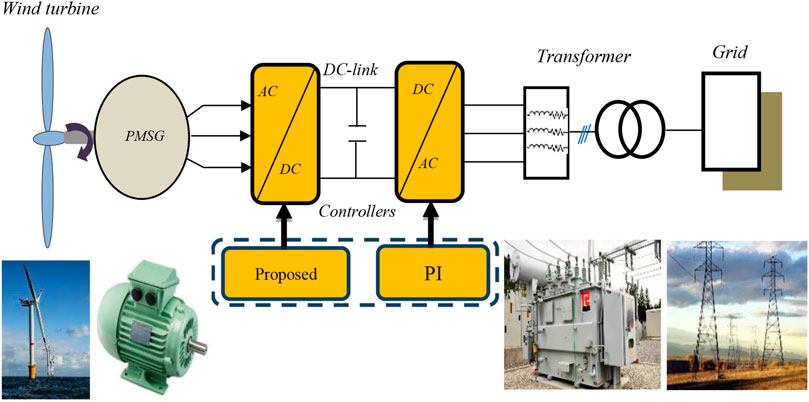
FIGURE 1. Wind power system.
Wind power
The wind energy converter model is represented as follows (Fantino et al., 2016; Belkhier et al., 2020):
where
Permanent magnet synchronous generator modeling
The PMSG modeling according to αβ-frame is needed to design the proposed technique, which is formulated as (Soliman et al., 2021; Belkhier et al., 2022):
where
Proposed controller computation
Several stages must be validated in order to build the developed technique: at first, the passivity attribute of the PMSG model must be demonstrated so that the suggested approach may be used. Second, the PMSG must be broken down into two passive subsystems with negative feedback. Finally, in order to construct a controller with a simple structure, the non-dissipative variables in the PMSG model must be formulated. Figure 2 depicts the explored strategy computing process, which has two distinct components: the first phase consists in designing the reference current using the computed electromagnetic torque and the high order sliding mode control (HSMC) technique, and the needed current is subsequently calculated using the required torque. In the second portion, the controller law is computed using the created method-based HSMC.
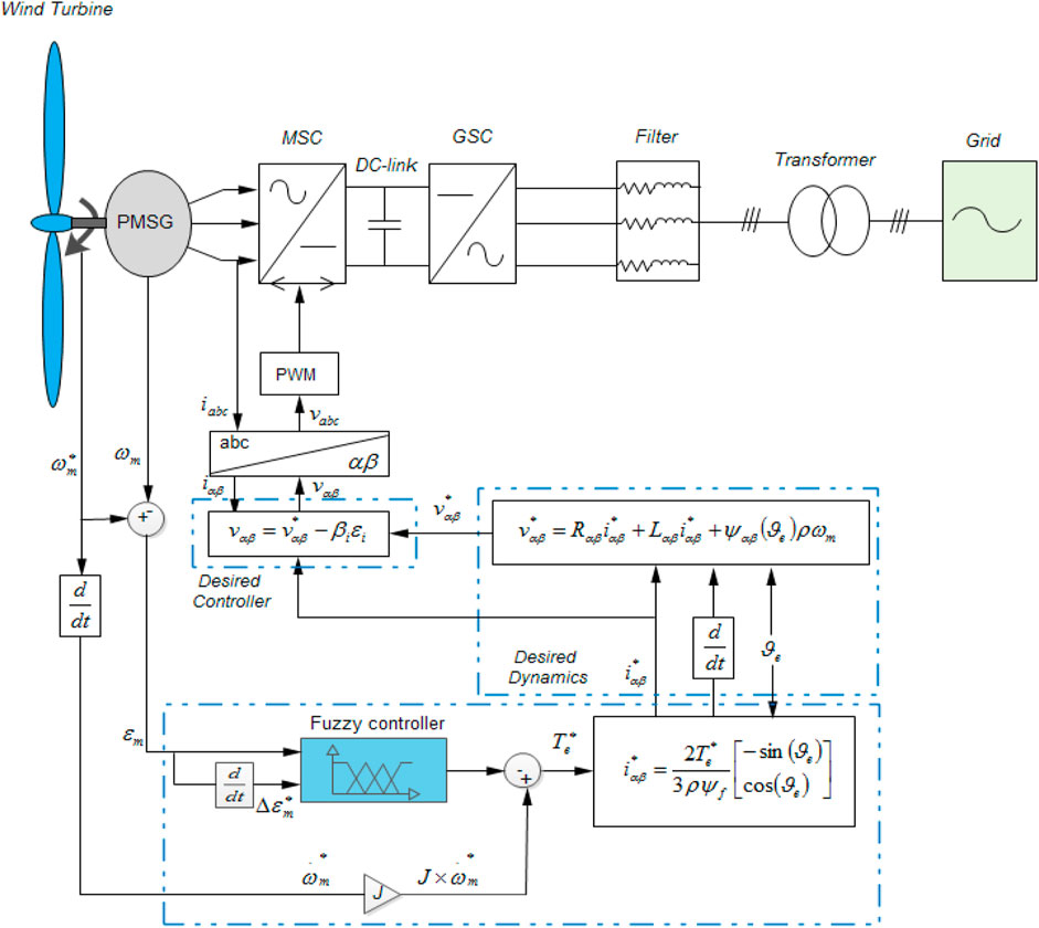
FIGURE 2. Schematic of the proposed controller.
PMSG αβ-model interconnected subsystems decomposition
From Eq. 6, the following relationship is formulated:
From Eqs 7, 8, the following relationship is formulated:
According to (9) and (10) the upcoming lemma is yield:
Lemma 1: according to the aforementioned conditions, the PMSG in the dq-model can be decomposed into feedback interconnected two passive subsystems, electrical subsystem
Proof: from (9), the following PMSG total energy
The time derivative of
Integrating on both sides of (12) along
Here,
where
It is clearly indicated that
It can be deduced that
PMSG passivity property
Lemma 2: the model (6)–(8) is passive, when
Proof: first, the PMSG Hamiltonian
Derivative along (6)–8) of
where
where
Then, relationship M is passive, which is the same for the PMSG.
Controller law design process
According to the model (6)–(8), one can formulate the reference dynamics given as follows:
where
Let us define the function
where
Thus, the controller law is deduced as follows:
where
Remark 2: the term
The proof of the convergence is given as follows:
Considering Eq. 25, where according to
where
According to dissipation term
where
From (28) and (29), it yields:
where
Integrating (30), yields:
From (28) and (31), we get:
where
Thus,
To forces the PMSG works at an optimal torque, the reference current is chosen as follows (Yang et al., 2018a):
From Equation 23, the reference torque is formulated as follows:
where
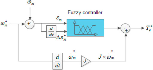
FIGURE 3. Desired torque computation.
The fuzzy manager is used for gain adjustment, which satisfies the requirements induced by inaccurate variables. The fuzzy values are either the speed error
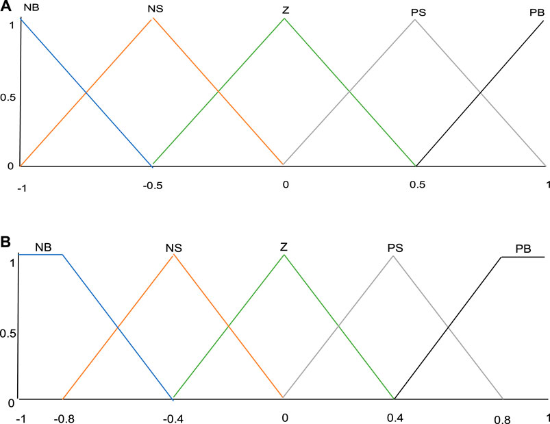
FIGURE 4. Fuzzy rules. (A) Function’s inputs (B) Outputs function.

TABLE 1. Fuzzy logic rules.
Grid-side model and PI controller
The GSC is modelized as given in Figure 5. The classical PI method is selected to regulate the GSC, which is formulated as (Yang et al., 2018a; Belkhier et al., 2020):
where
where
where
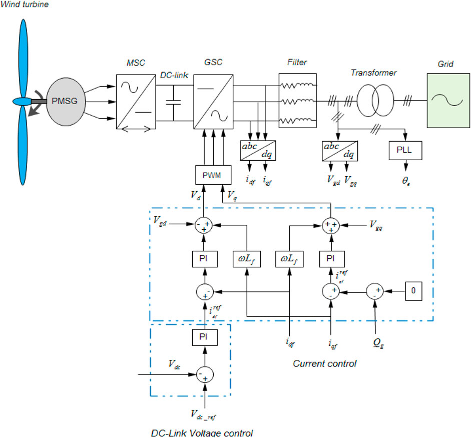
FIGURE 5. GSC PI controller schematic.
Extensive numerical investigation and experimental validation
For the simulation of the system, the average value of the wind speed is fixed at 12 m/s, and the reference of the wind turbine speed ref is estimated from the generator. The reference of the reactive power is set to 0 kVAr. The parameter values of the system are given in Table 2. The reference of the DC-bus voltage is set to 1150 V. The network is assumed to have infinite power, which allows the injection of all the production without constraints. The damping value is
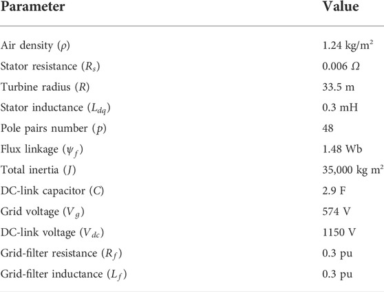
TABLE 2. Parameters of the system.
Fixed parameters performance analysis
Figure 6 indicates the wind velocity profile applied on the conversion mechanism. Figure 7 depicts the DC-bus trailing behavior with exceptionally low error (ɛ (
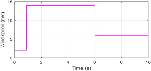
FIGURE 6. Wind speed.
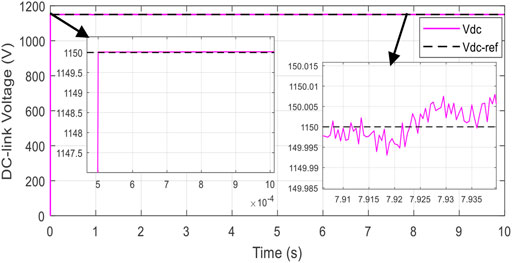
FIGURE 7. DC-link voltage.
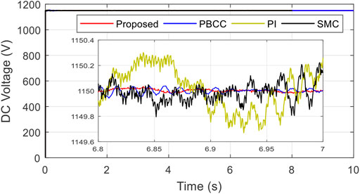
FIGURE 8. DC-link response compared with conventional controls.
Figure 9 depicts the tracking error (ɛ (
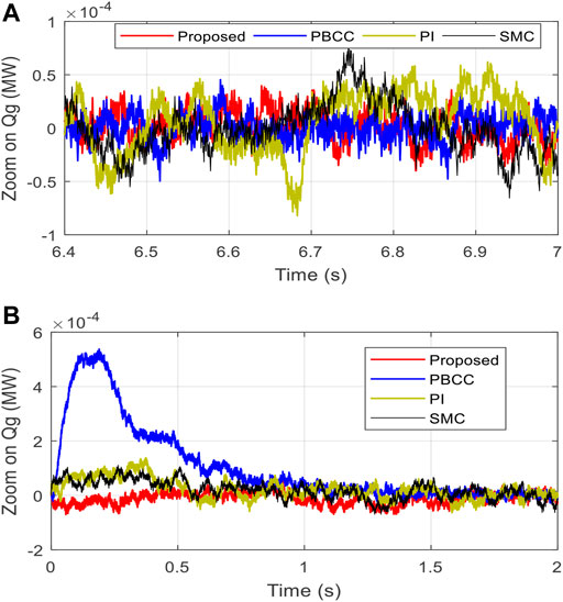
FIGURE 9. Reactive power response of the tested controls.
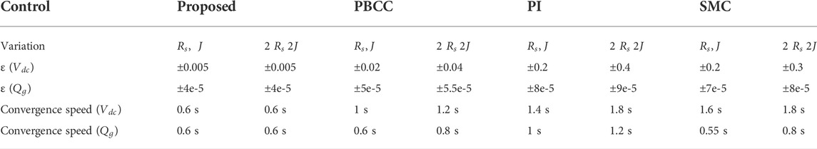
TABLE 3. Results comparison of the control strategies.
Parameter changes performance analysis
In the present sub-section, simultaneous changes of +100%
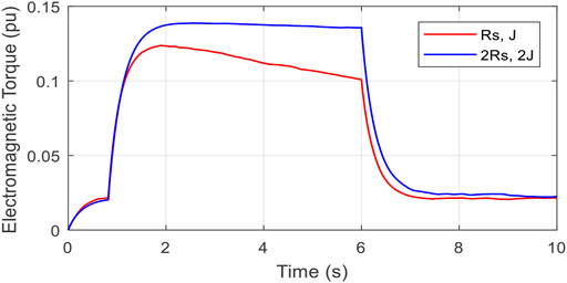
FIGURE 10. Zoom on convergence speed of the reactive power.
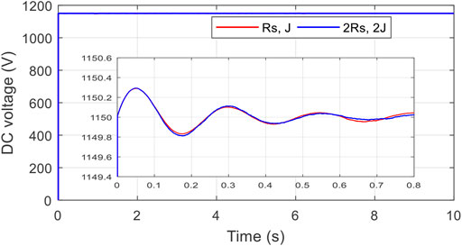
FIGURE 11. Electromagnetic torque under parameter changes.
Figure 12 indicates the resemblance monitoring reaction of
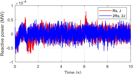
FIGURE 12. DC-link voltage under parameter changes.
Figure 13 depicts the
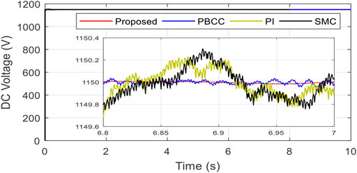
FIGURE 13. Reactive power response under parameter changes.
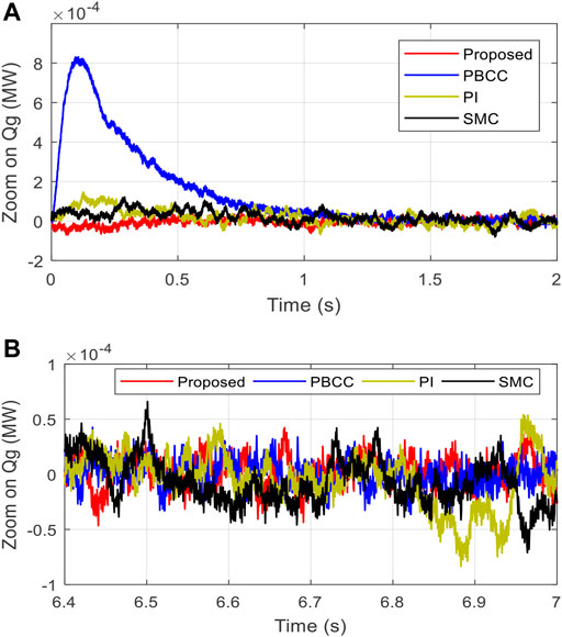
FIGURE 14. DC-link response of the tested controls under parameter changes.
As per the reported findings, the suggested fuzzy-EBC has a lower tracking error below these variations than PBCC (5.5e-5), PI (9e-5), and SMC (8e-5), as shown in Table 3. Moreover, the suggested fuzzy-PBC clearly outperforms the other alternatives in terms of velocity position error ɛ (
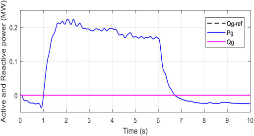
FIGURE 15. Reactive power response of the tested controls under parameter changes.
FIGURE 16. Zoom on reactive power response of the tested controls under parameter changes
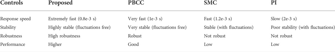
TABLE 4. Performance comparisons of the tested controls.
FIGURE 17. Active and reactive powers response.
Experimental testing
The processor-in-the-loop testing (PiL) is the process of testing and validating embedded software on the processor before it is utilized in the electronic control unit (ECU). Algorithms and functions are often created on a PC in a development environment. More details about processor-in-the loop experimentation are reported in Ullah et al. (2020); Ullah et al. (2021a); Ullah et al. (2021b). PiL tests are run to ensure that the built code also runs on the target CPU. The control algorithms for the PiL test are often run on a device known as an evaluation board. PiL testing is sometimes run on the actual ECU. Both types use the controller’s actual processor rather than the PC as in software-in-loop (SiL) testing. The target processor offers the advantage of detecting compiler issues. As a result of the preceding work, the suggested control systems are evaluated utilizing PIL investigation, and the block diagram of the setup is illustrated in Figure 18. In the PIL investigation, the DSP command board is physically interconnected with the simulated converter system. The control board is made up of a double core processor TMS320F379D that was developed using the Simulink planet’s simple synthesis approach. Simulink is used to create discontinuous versions of the described devices, and the output or hex file is loaded into the processor’s random-access memory (RAM).
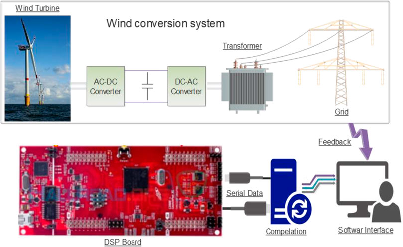
FIGURE 18. Experimental Step.
In PiL testing, “in-the-loop” indicates that the controller is integrated in physical machine and the program during test’s surroundings is emulated. The wind profile utilized in the PIL testing is depicted in Figure 19. Figures 20 and 21, which demonstrate the experimental findings for DC-link voltage, active, and reactive powers obtained using the PIL approach. Based on the provided data, the proposed fuzzy-EBC is definitely applicable in practice.
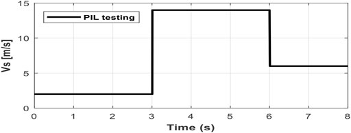
FIGURE 19. Wind profile used for the PIL experiment.
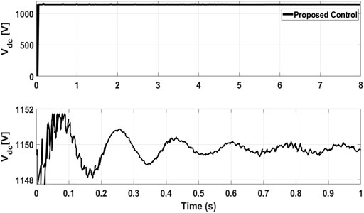
FIGURE 20. PIL testing DC voltage.
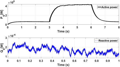
FIGURE 21. PIL testing grid powers.
6 Conclusion
For a PMSG in a wind power converter, a new fuzzy energy-based controller is presented. To obtain the maximum power out of wind energy, utilize the suggested strategy where the entire dynamics of the PMSG is considered when designing the control law. A fuzzy controller is selected to guarantee the overall-rated speed operation of the PMSG, and then compute a higher reference torque. Dynamic simulations of the studied system under parameter changes have taken special attention, and the results have been compared to conventional methods, which show a quick track of the DC voltage and reactive energy to their set values over the compared controls. All of the conversion system’s flaws have been fixed, and the goals have been met. The designed control approach offers optimum performance as well as increased resilience. Moreover, the PIL experiment is conducted to prove that the proposed controller is practically implementable. Future works will be focused on:
• Experimental validation of the proposed control on a real wind energy system.
• The adaptation of the damping fixed gain by introducing an optimization algorithm.
Data availability statement
The original contributions presented in the study are included in the article/Supplementary Material; further inquiries can be directed to the corresponding author.
Author contributions
All authors listed have made a substantial, direct, and intellectual contribution to the work and approved it for publication.
Conflict of interest
The authors declare that the research was conducted in the absence of any commercial or financial relationships that could be construed as a potential conflict of interest.
Publisher’s note
All claims expressed in this article are solely those of the authors and do not necessarily represent those of their affiliated organizations, or those of the publisher, the editors, and the reviewers. Any product that may be evaluated in this article, or claim that may be made by its manufacturer, is not guaranteed or endorsed by the publisher.
References
Belkhier, Y., and Achour, A. (2020). Fuzzy passivity-based linear feedback current controller approach for PMSG-based tidal turbine. Ocean. Eng. 218, 108156. doi:10.1016/j.oceaneng.2020.108156
Belkhier, Y., Achour, A., Ullah, N., Shaw, R. N., Chowdhury, S., and Techato, K. (2022). Energy-based fuzzy supervisory non integer control for performance improvement of PMSG-Based marine energy system under swell effect and parameter uncertainties. Renew. Energy 186, 457–468. doi:10.1016/j.renene.2021.12.126
Belkhier, Y., and Achour, A. Y. (2020). An intelligent passivity-based backstepping approach for optimal control for grid-connecting permanent magnet synchronous generator-based tidal conversion system. Int. J. Energy Res. 45, 5433–5448. doi:10.1002/er.6171
Belkhier, Y., Achour, A. Y., Ullah, N., and Shaw, R. N. (2020). Modified passivity-based current controller design of permanent magnet synchronous generator for wind conversion system. Int. J. Model. Simul. 42, 192–202. doi:10.1080/02286203.2020.1858226
Bigarelli, L., Benedetto, M. D., Lidozzi, A., Solero, L., Odhano, S. A., and Zanchetta, P. (2020). PWM-based optimal model predictive control for variable speed generating units. IEEE Trans. Ind. Appl. 56 (1), 541–550. doi:10.1109/tia.2019.2955662
Chandrasekaran, K., Mohanty, M., Golla, M., Venkadesan, A., and Simon, S. P. (2020). Dynamic MPPT controller using cascade neural network for a wind power conversion system with energy management. IETE J. Res., 1–15. doi:10.1080/03772063.2020.1756934
Soliman, M. S., Belkhier, Y., Ullah, N., Achour, A., Alharbi, Y. M., Al Alahmadi, A. A., et al. (2021). Supervisory energy management of a hybrid battery/PV/tidal/wind sources integrated in DC-microgrid energy storage system. Energy Reports 7, 7728–7728.
Fantino, R., Solsona, J., and Busada, C. (2016). Nonlinear observer-based control for PMSG wind turbine. Energy 113, 248–257. doi:10.1016/j.energy.2016.07.039
Haq, I. U., Khan, Q., Khan, I., Akmeliawati, R., and Nisar, K. S. (2020). Maximum power extraction strategy for variable speed wind turbine system via neuro-adaptive generalized global sliding mode controller. IEEE Access 8, 128536–128547. doi:10.1109/access.2020.2966053
Jlassi, I., and Cardoso, A. J. M. (2019). Fault-tolerant back-to-back converter for direct-drive PMSG wind turbines using direct torque and power control techniques. IEEE Trans. Power Electron. 34 (11), 11215–11227. doi:10.1109/tpel.2019.2897541
Michael, A., and Takagi, H. (1993). “Dynamic control of genetic algorithms using fuzzy logic techniques,” in Proceedings of the Fifth International Conference on Genetic Algorithms (Morgan Kaufmann), 76–83.
Mohammadi, E., Fadaeinedjad, R., and Nadji, H. R. (2019). Design, electromechanical simulation, and control of a variable speed stall-regulated PMSG-based wind turbine. Int. J. Green Energy 16 (12), 890–900. doi:10.1080/15435075.2019.1641714
Nicklasson, P. J., Ortega, R., and Espinosa-Perez, G. (1994). Passivity-based control of the general rotating electrical machine. Proc. 1994 33rd IEEE Conf. Decis. Control 4, 4018–4023. doi:10.1109/CDC.1994.411573
Rizk-Allah, R. M., Hassanien, A. E., and Song, D. (2022). Chaos-opposition-enhanced slime mould algorithm for minimizing the cost of energy for the wind turbines on high-altitude sites. ISA Trans. 121, 191–205. doi:10.1016/j.isatra.2021.04.011
Saidi, Y., Mezouar, A., Miloud, Y., Kerrouche, K. D. E., Brahmi, B., and Benmahdjoub, M. A. (2019). Advanced non-linear backstepping control design for variable speed wind turbine power maximization based on tip-speed-ratio approach during partial load operation. Int. J. Dyn. Control 8, 615–628. doi:10.1007/s40435-019-00564-3
Song, D., Li, Z., Wang, L., Jin, F., Huang, C., Xia, E., et al. (2022). Energy capture efficiency enhancement of wind turbines via stochastic model predictive yaw control based on intelligent scenarios generation. Appl. Energy 312, 118773. doi:10.1016/j.apenergy.2022.118773
Song, D., Tu, Y., Wang, L., Jin, F., Li, Z., Huang, C., et al. (2022). Coordinated optimization on energy capture and torque fluctuation of wind turbines via variable weight NMPC with fuzzy regulator. Appl. Energy 312, 118821. doi:10.1016/j.apenergy.2022.118821
Subramaniam, R., and Joo, Y. H. (2019). Passivity-based fuzzy ISMC for wind energy conversion systems with PMSG. IEEE Trans. Syst. Man. Cybern. Syst. 51, 2212–2220. doi:10.1109/tsmc.2019.2930743
Ullah, N., Farooq, Z., Sami, I., Chowdhury, M. S., Techato, K., and Alkhammash, H. I. (2020). Industrial grade Adaptive control scheme for a micro-grid integrated dual active bridge driven battery storage system. IEEE Access 8, 210435–210451. doi:10.1109/ACCESS.2020.3039947
Ullah, N., Sami, I., Chowdhury, M. S., Techato, K., and Alkhammash, H. I. (2021a). Artificial intelligence integrated fractional order control of doubly fed induction generator-based wind energy system. IEEE Access 9, 5734–5748. doi:10.1109/ACCESS.2020.3048420
Ullah, N., Sami, I., Jamal Babqi, A., I Alkhammash, H., Belkhier, Y., Althobaiti, A., et al. (2021b). Processor in the loop verification of fault tolerant control for a three phase inverter in grid connected PV system. Energy Sources, Part A Recovery, Util. Environ. Eff., 1–17. doi:10.1080/15567036.2021.2015486
Wang, X., and Wang, S. (2020). Adaptive fuzzy robust control of PMSM with smooth inverse based dead-zone compensation. Int. J. Control Autom. Syst. 14 (2), 378–388. doi:10.1007/s12555-015-0010-6
Yang, B., Wu, Q. H., Tiang, L., and Smith, J. S. (2013). Adaptive passivity-based control of a TCSC for the power system damping improvement of a PMSG based offshore wind farm. Madrid, Spain: IEEE International Conference on Renewable Energy Research and Applications ICRERA, 1–5.
Yang, B., Yu, H., Zhang, Y., Chen, J., Sang, Y., Jing, L., et al. (2018a). Passivity-based sliding-mode control design for optimal power extraction of a PMSG based variable speed wind turbine. Renew. Energy 119, 577–589. doi:10.1016/j.renene.2017.12.047
Yang, B., Yu, T., Shu, H., Qiu, D., Zhang, Y., Cao, P., et al. (2018b). Passivity-based linear feedback control of permanent magnetic synchronous generator-based wind energy conversion system: Design and analysis. IET Renew. Power Gener. 12 (9), 981–991. doi:10.1049/iet-rpg.2017.0680
Yubazaki, N., Otani, M., Ashida, T., and Hirota, K. (1995). “Dynamic fuzzy control method and its application to positioning of induction motor,” in Proceedings of 1995 IEEE International Conference on Fuzzy Systems (IEEE), 1095–1102.3
Keywords: renewable energy systems, fuzzy logic control, processor-in-the loop (PIL) experiments, nonlinear control, power extraction
Citation: Jaiswal A, Belkhier Y, Chandra S, Priyadarshi A, Bajaj M, Pushkarna M, Elgamli E, Shouran M and Kamel S (2022) Design and implementation of energy reshaping based fuzzy logic control for optimal power extraction of PMSG wind energy converter. Front. Energy Res. 10:966975. doi: 10.3389/fenrg.2022.966975
Received: 12 June 2022; Accepted: 12 July 2022;
Published: 28 September 2022.
Edited by:
Dongran Song, Central South University, ChinaCopyright © 2022 Jaiswal, Belkhier, Chandra, Priyadarshi, Bajaj, Pushkarna, Elgamli, Shouran and Kamel. This is an open-access article distributed under the terms of the Creative Commons Attribution License (CC BY). The use, distribution or reproduction in other forums is permitted, provided the original author(s) and the copyright owner(s) are credited and that the original publication in this journal is cited, in accordance with accepted academic practice. No use, distribution or reproduction is permitted which does not comply with these terms.
*Correspondence: Elmazeg Elgamli, RWxnYW1saWVzQGNhcmRpZmYuYWMudWs=