 Lei Fu
 Yujie Diao1
- 1Center for Hydrogeology and Environmental Geology Survey, Baoding, China
- 2Qinghai Hydrogeology and Engineering Geology and Environgeology Survey Institute, Xining, China
- 3Hydrogeological and Geothermal Geological Key Laboratory of Qinghai Province, Xining, China
As a bottom technology for CO2 reduction, geological CO2 storage has attracted great attention from geologists, but there are few reports on the research of the caprock self-sealing effect due to CO2 leakage. Ping’an is a natural CO2 leakage site, which can be compared to the leakage scenarios of geological CO2 storage. Based on the water quality test results and geological observation data, the numerical simulation of geochemistry is carried out. The results show that: First, gypsum dissolves and calcite precipitates during the migration of CO2-rich water to the surface. This process presents a self-sealing effect, and the closer to the surface, the more obvious the self-sealing; Second, the self-sealing effect is formed rapidly. For a 30 cm wide fissure, it only takes a few hundred days to achieve self-sealing; Third, the CO2 leakage was estimated, about 140,813.3 m3, or about 251.28 tons for 1 m long fissure.
Introduction
Geological CO2 storage (GCS) is considered to be an effective solution to alleviate global warming and environmental degradation because it can absorb greenhouse gases on a large scale (Jefferson, 2015). However, due to the complex deep geological conditions, unexpected geological events and human engineering activities, the risk of CO2 leakage still exists (Xu et al., 2008). Potential leakage pathways for sequestered CO2 include wells, faults, and “weak zones” in the caprock (Xie et al., 2017).
CO2 leakage can cause serious geological environmental problems, such as the pollution of freshwater aquifers, and the enrichment of CO2, which endangers nearby human health and local ecosystems (Cui et al., 2011; Jonathan et al., 2014; Ren et al., 2014; Taylor and Stahl, 2015; Vialle et al., 2016; Zhao et al., 2017; Zhai et al., 2018; Ma et al., 2020; Xiao et al., 2022). Many scholars have used a variety of methods to study the mechanism of CO2 leakage and migration, the environmental impact and prevention measures. For example, Roberts has studied the relationship between the lithology, structure and leak location of a natural CO2 spring in Daylesford, Australia (Roberts et al., 2019). Ma D explored the identification method of geological CO2 storage leakage based on neural network (Ma et al., 2020). Gal et al. studied CO2 leakage and migration paths through controlled release experiments in shallow formations (Gal et al., 2013; Do et al., 2022; Melis et al., 2015; Schroder et al., 2017; Jones et al., 2014). Erik uses the method of analog gas well leakage to study the leakage path and leakage mechanism under the worst-case scenario of CO2 geological storage (Erik et al., 2017). Mark L et al. studied the interception and accumulation effects of heterogeneous caprocks on CO2 gas through laboratory experiments and numerical simulations (Mark et al., 2014; Ha et al., 2017; Saleem et al., 2021). Taking a natural CO2 gas reservoir leaking site in South Africa as an object, Johnson used an analogy method to study the leakage of CO2 geological storage along wells and faults (Johnson et al., 2017). Anelia et al. studied the effect of CO2 leakage on the physical and chemical indicators of shallow aquifers (Susan et al., 2014; Qafoku et al., 2017; Choi, 2019; Delkhahi et al., 2020; Anelia et al., 2021). Li Xiaochun et al. used geomechanical modeling and numerical simulation to evaluate the sealing ability of caprock and the risk of fault activation in CO2 storage sites (Li et al., 2003; Gale, 2004; Cui et al., 2011). Karas et al. introduced the repair measures and plugging effect of natural CO2 gas reservoir leakage caused by blowout in Serbia (Karas et al., 2016). Zahasky C analyzes the feasibility of controlling reservoir pressure through injection-producer wells to stop CO2 leakage (Zahasky and Benson, 2016).
Although many important achievements have been made in the migration path, environmental impact, and response measures of CO2 geological storage leakage, the research on the self-sealing effect of CO2 geological storage leakage are rarely reported. There are many natural CO2 springs in Ping’an, which can be used to study the leakage scenarios of CO2 geological storage by analogy. And there are many travertine platforms associated with the springs. The veins filled in the platform fissures provide a good research object for studying the self-sealing effect of CO2 geological storage leakage.
Geological background
The study area is located in Ping’an County, Qinghai Province, China. The landform are mainly low mountains and hills, with an altitude of about 2400 m. The terrain is high in the south and low in the north. The tectonic structure is in the transition zone from the Loess Plateau to the Qinghai-Tibet Plateau. Affected by regional structure, it mainly develops two sets of faults. The NNE trending faults are extensional and torsional, and the NWW are compressional and torsional (Figure 1). Secondary tectonic units divided by faults have different hydrogeological conditions.
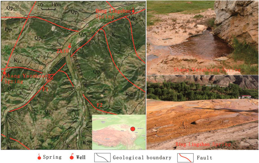
FIGURE 1. Geological scheme of the study area.
The structure of the study area is located in the Ping’an Sag of the Xining Basin. As a secondary structural unit of the Xining Basin, the Ping’an Sag has a deep basement and well-developed strata. The Proterozoic strata constitute the crystalline basement. The upper strata are dominated by Mesozoic Cretaceous sandstone, glutenite and Cenozoic mudstone and siltstone. Quaternary aeolian, alluvial, ice-water deposits and a small amount of travertine deposits are widely distributed (Fu et al., 2019; Gupta and Yadav, 2020).
The Minhe Formation is mainly exposed in the study area, which is a lakeside sedimentary facies, and the lithology is mainly gypsum-bearing clastic rock. The lower part is dominated by conglomerate, which together with the underlying Early Cretaceous Estuary Group constitute the main reservoir in the region, with a thickness of 320.4–1,374.3 m. The upper part of the Minhe Formation is dominated by mudstone and silty mudstone, interspersed with fine sandstone and gypsum layers, with a thickness of 85.4–201.4 m, forming a regional caprock.
There are many natural CO2 leakage points in the Ping’an area, including the Bing Lingshan spring, Shang Yaozhuang spring, and the ZK10 hole (Figure 1). Bing Lingshan spring is about 4.2 km northeast of Sanhe Town, with a water temperature of 19.5°C. There are sand gushing and bubbling in the spring, and a large thickness of travertine is developed. Shang Yaozhuang spring is about 6.4 km southwest of Sanhe Town, with a water temperature of 17.0°C. The spring is gushing sand and bubbling, and there is a large thickness of travertine around. ZK10 hole is located in the terrace of Qijiachuan Valley, 0.5 km southwest of Sanhe Town. It was the first time that high-pressure artesian water containing CO2 gas was exposed in the Ping’an Sag. The depth of the well is 212.43 m, and the thickness of the aquifer containing CO2 gas is 35.09 m. At the end of drilling in 2002, the water head was 73.00 m above the surface, and the artesian flow was 156.82 m3/d. At present, the artesian flow has been greatly reduced, and it is speculated that the wellbore may be self-sealed by sediment. The well water temperature is 17.0°C, the salinity is 2.94 g/L, and the water chemical type is HCO3·SO4-Ca.
The ZK10 borehole is 212.43 m deep and mainly encounters the Minhe Formation (K2m). The 0–132.18 m stratum is dominated by brown-red mudstone, intercalated with thin layers of siltstone, which is a closed caprock for CO2 sequestration; below 132.18 m is an interbed of gray-white fine sandstone and argillaceous sandstone, which contains water and gas, and is a CO2 reservoir. When the borehole was drilled to 51 m, artesian water associated gas were found. After the drilling is completed, the still water level is 73 m above the surface. Under the premise that the reservoir is not exposed, water and gas are encountered in the closed caprock, indicating that the upper strata of the Minhe Formation have poor sealing performance. Under these conditions, deep CO2 leaks to the surface in some way, as confirmed by a nearby natural CO2 spring.
Methods and results
CO2 source
The sources of CO2 in groundwater can be roughly divided into organic and inorganic origins. Organic CO2 mainly refers to the CO2 produced by the decomposition of organic matter in the near-surface soil or by the respiration of plant roots. Inorganic CO2 mainly related to deep metamorphism or magmatic activity, including the CO2 produced by the pyrolysis of carbonate minerals, and the CO2 carried in the hydrothermal fluid after the magmatic stage.
The origin of CO2 can be identified according to δ13C, 3He/4He and R/Ra (3He/4He ratio of sample to standard air). The δ13C value of organic CO2 is generally less than -10‰, and the R/Ra is less than 1. The δ13C value of inorganic origin CO2 is greater than 8‰. According to 3He/4He and R/Ra, inorganic CO2 can be further divided into crust-derived type, mantle-derived type and mixed crust-mantle type. The 3He/4He of crust-derived type is low, and the R/Ra value is less than 1. The 3He/4He of mantle-derived type is high, and R/Ra is greater than 2. And the mixed crust-mantle type, due to the combined effect of the two factors, has an R/Ra value in the range of 1–2.
The gas composition and isotope analysis of typical CO2 leakage sites in Ping’an are carried out, and the results are shown in Table 1. According to the results, the components in the gas sample are relatively simple, the main component is CO2, and the content is more than 87.63%. Others are nitrogen, oxygen and trace argon, while hydrogen sulfide, hydrogen, methane and other alkanes were not detected. The δ13C value of CO2 gas reservoirs in the study area is -1.5‰ to -2.5‰, indicating that the CO2 gas is inorganic origin. The lower values of 3He/4He and R/Ra indicate that the CO2 gas lacks the participation of mantle fluids, which is a typical crust-derived type.
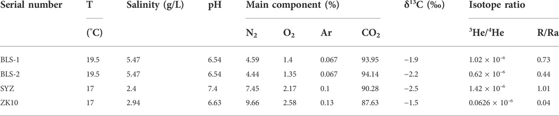
TABLE 1. Gas composition and isotope analysis of CO2 leakage points in the study area.
The study area is geothermally abnormal, and the distribution of numerous hot springs and high terrestrial heat flow also confirm the existence of deep heat sources. Therefore, it is speculated that the main source of CO2 in the study area is the pyrolysis of deep carbonate in the crust.
Water chemistry
Water samples from natural CO2 leak sites in the study area were tested for hydrochemistry. The water sample numbers of Bing Lingshan spring, Shang Yaozhuang spring and ZK10 boreholes are BLS, SYZ and ZK10 respectively. The water quality was analyzed by AT-510 automatic titration analyzer, and the results are shown in Table 2. The results show that SYZ and ZK10 have the same water chemical type, which is HCO3·SO4-Ca; and the water chemical type of BLS is HCO3·SO4-Na·Ca. Different hydrochemical types indicate that Bing Lingshan spring is in different hydrogeological units with ShangnYaozhuang spring and ZK10 borehole.
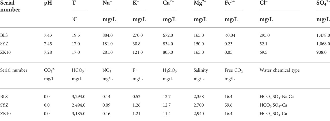
TABLE 2. Hydrochemical analysis of CO2 leakage site.
Plot the Na-K-Mg giggenbach diagram with the water chemistry data of the three samples to judge the equilibrium degree of the water-rock reaction (Figure 2). The results show that the three samples all fall in the unbalanced water area of the giggenbach diagram, indicating that during the migration of water along the fractures of the caprock to the surface, the dissolution and precipitation reaction will occur, which may promote the self-sealing of the caprock.
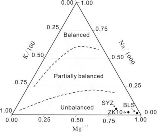
FIGURE 2. Na-K- Mg giggenbach plot with samples in the study area.
Microscopic morphology of veins
There are three forms of travertine. The first is the travertine veins developed in the bedrock strata; the second is the travertine platform cemented by the springs; the third is the chemical accumulation formed at the mouth of the hot spring and the wellhead of the geothermal well. The travertine veins filled in the fractures of the bedrock have the deepest influence, and have the most significant influence on GCS.
The area of travertine in Bingling Mountain reaches 0.5 km2. Affected by the uplift of neotectonic movement, the springs moved down to form three travertine platforms with a height difference of less than 30 m. The travertine platform is distributed in the SW-NE direction. The third-level platform in the SW direction is high and ancient, and the first-level platform in the NE direction is low and new. The third-level travertine platform is about 10 m thick, covered with Malan loess, and the lower stratum is Minhe Formation calcareous siltstone. The profile shows a number of vertical travertine veins, which are formed by the mineral precipitation in the original water-conducting fissures. It affirms the existence of the self-sealing effect of the caprock, and provides a good research target for studying the travertine self-sealing.
A typical travertine vein is selected for research (Figure 3). The thick of the vein is 24–30 cm, and can be divided into four layers from the center to the edge, representing four self-sealing stages. Described in order of formation time from late to early. The first layer is located in the middle of the vein, 6–8 cm thick, massive, uniform in texture, and earthy gray; the second layer is about 2 cm thick, in the shape of thin strips, including seven small laminae, alternating light and dark, with a single thin layer about 2 mm; the third layer is about 2–3 cm thick, massive, uniform in texture, light brown, with a longitudinal bright crystal calcite vein inside; the fourth layer is about 1–4 cm thick, in the shape of thin strip, including six small laminae, with a single layer thickness of 1–2 mm.
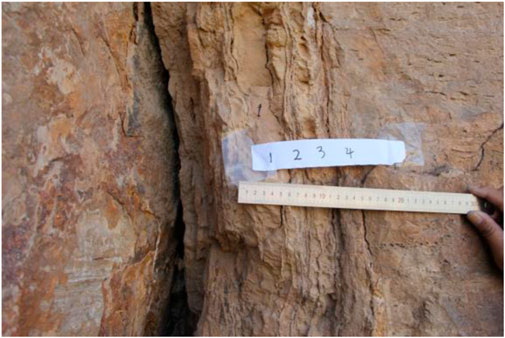
FIGURE 3. Photo of travertine vein in Bing Lingshan.
The vein The SEM photos of BLS01 and BLS02 are shown in Figure 4. BLS01 has a uniform structure, mainly composed of calcite and quartz. The sediment has a large particle size and a low clay content. It is speculated that the provenance was abundant and the deposition was rapid. BLS02 shows the contact relationship of laminae. The two sides are mainly calcite. The contact zone is composed of gypsum, biotite and illite. It is speculated that the two sides of the contact surface were formed in different stages. The small particle size of the sediment and the high content of clay minerals indicate that the sedimentation process was slow, the provenance was few and unstable.
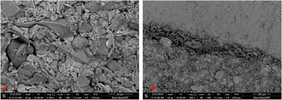
FIGURE 4. The SEM photos of BLS01(A) and BLS02 (B).
REE in travertine
Travertine veins are the product of the interaction between fluid and deep fractured rock mass. It reflects the chemical composition of groundwater and is used to analyze the source of water supply. It can also reflect the temperature and pressure conditions and surrounding rock information of the fracture system.
As a special element, rare earth elements (REE) occupy an important position in geochemical research. Because of their similar chemical properties, they coexist in nature, but there are slight differences in atomic structure, resulting in certain differences in the chemical properties of each element. Therefore, REE can undergo a certain fractionation in different geological processes, resulting in their distribution patterns with different characteristics. Based on this, according to the content data of REE in rocks and minerals, the chemical composition of the ancient fluid medium, the characteristics of the source area and the regional evolution history can be discussed.
REE analysis was carried out on the four travertine samples (Tables 3, 4), and the chondrite standard spider diagram and NASC normalized patterns were drawn as shown in Figures 5, 6. According to the distribution pattern of REE, the samples can be divided into two groups, BLS01 and BLS03 as a group, and BLS02 and BLS04 as a group. This result is consistent with the morphology of travertine, indicating that BLS01 and BLS03, BLS02 and BLS04 samples have different material sources and formation processes.
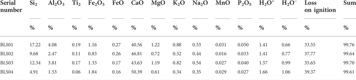
TABLE 3. Chemical analysis results of travertine samples.
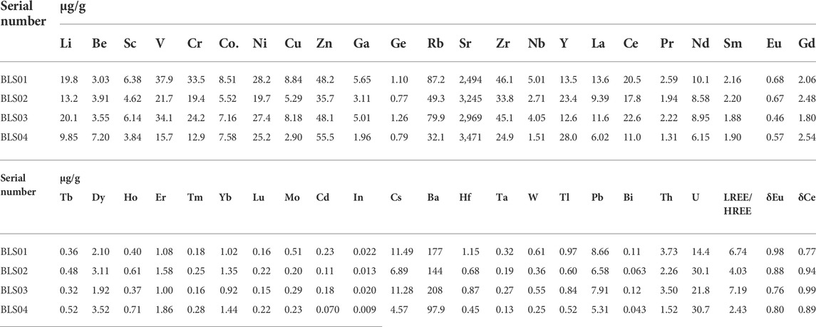
TABLE 4. Trace elements analysis of travertine samples.
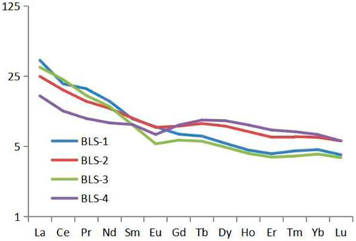
FIGURE 5. Travertine REE chondrite standard spider diagram.

FIGURE 6. NASC normalized patterns of REE in travertine.
Numerical simulation
PHREEQC software was used for simulation. It is a powerful hydrogeochemical simulation software developed by the US Geological Survey and widely used in the field of hydrogeology. It is based on the water chemistry model of ionic connection, which can simulate reversible reactions such as mineral dissolution and precipitation, surface complexation, ion exchange, and irreversible reactions such as mixing with solution and redox. It can also do reverse modeling and find that minerals and gases transfer in water with indeterminate compositions. This software can simulate the mineral dissolution and precipitation reaction caused by pressure reduction and CO2 overflow during the migration of CO2-rich fluid to the surface, and is suitable for the study of self-sealing of CO2 geological storage.
A conceptual model was established based on the vein body shape of the travertine platform in Bing Lingshan and the strata of the ZK10 borehole (Figure 7). The caprock is 200 m thick, and the lower part is a confined aquifer containing CO2 gas. The fissure is 0.3 m wide and runs through the caprock longitudinally. The pressure at the bottom of the fissure is 28 atm, gradually reaching 1 atm to the surface, and the CO2-rich fluid migrates from the reservoir to the surface along the fissure, and finally emerges into a spring. The fluid in the reservoir is in the supersaturated state of CO2, and the main water quality ion indicators are set according to the ZK10 borehole water quality analysis results. The main ionic components are shown in Table 5.
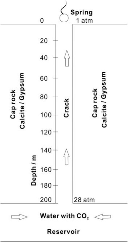
FIGURE 7. Caprock Self-sealing model of the CO2 leakage site.
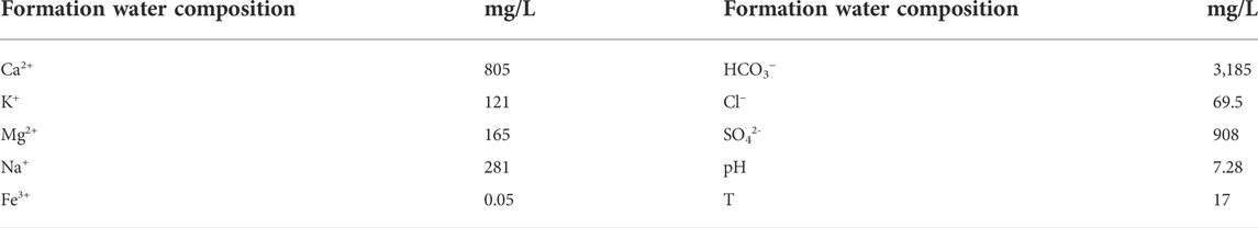
TABLE 5. Main ionic components in groundwater.
CO2 partial pressure and temperature have no effect on the reaction of feldspar and clay minerals, but these factors have a great influence on the reaction of calcite and gypsum. In this study, only calcite and gypsum were considered. The temperature of the fluid from the reservoir to the surface changes little, and only the effect of pressure on the solubility of CO2 is considered. In the process of fluid migration to the surface, the single-width flow rate of fluid is set to 2 L/s, and the fluid is in equilibrium with the calcite and gypsum in the caprock.
The simulation results are shown in Figure 8. In the figure, it can be seen that gypsum dissolves and calcite precipitates during the migration of CO2-rich water to the surface, and the closer to the surface, the greater the rate of dissolution and precipitation. During this process, the volume of precipitated calcite is larger than that of dissolved gypsum, and the overall performance is self-sealing of fissures, and the closer to the surface, the more obvious the self-sealing phenomenon.
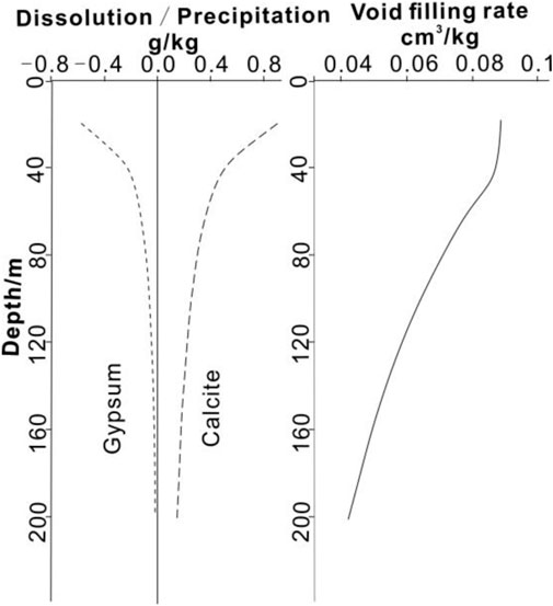
FIGURE 8. Mineral dissolution/precipitation and void filling rate variation curve with depth.
Discussion
CO2 leakage mechanism in Qinghai Ping’an
There are two sets of faults in the study area. The NNE-trending extensional faults have water-conducting properties, and the NWW-trending faults have water-blocking properties. NNE-trending extensional faults are developed along Qijiachuan (F1), and the outcropping lithology of the mountains on both sides of the fault is different. On the west side, the upper part of the Minhe Formation is exposed with fine-grained mudstone mixed with gypsum, which is a relatively descending depression; and on the east side, the coarse-grained strata in the lower part of the Minhe Formation is exposed, which is a relatively rising bulge. A south-dipping compressional fault (F2) is developed near the east-west direction on the south side of Sanhe Town. The study area is divided into checkerboard-like structural units by two sets of faults. In addition, on the north side of the F2 fault, there is an open syncline structure with an axial distribution in a near-north-south direction and the hub dipping to the north. The ZK10 borehole is located in good structural sealing conditions, with sufficient groundwater recharge source and good fault water storage structure. At the same time, the syncline structure and groundwater runoff also easily promote the migration and accumulation of CO2 to the two flanks of the syncline structure, and then leak into spring along the fault.
The ZK10 borehole has intermittent CO2 self-spraying phenomenon during construction. The eruption period is about 10 min, and the self-spraying duration is 210 s. The maximum instantaneous self-spraying water volume is 5835 m3/d. The reason for this phenomenon is presumed that deep CO2 migrates upwards into the reservoir through deep and large faults, and is blocked by the caprock. When the position is affected by the pressure reduction and volume expansion, the self-spray phenomenon occurs. The reason for this phenomenon is speculated to be that deep CO2 migrated upward into the reservoir through deep and large faults. Prevented by the caprock, CO2 accumulates on top of the reservoir. CO2 migrates with the groundwater in the reservoir, and when it migrates to the wellbore position, a self-spray phenomenon occurs, which is affected by pressure reduction and volume expansion.
Based on the above, there are three leakage channels in natural CO2 gas reservoirs in the study area, including drilling holes, faults, and the “weak caprock zone” verified by hole ZK10. The natural CO2 leakage mechanism in the study area is as follows: the deep carbonate minerals in the crust are decomposed at high temperature to generate CO2, and the generated CO2 rises into the reservoir along with the deep and large fault. Blocked by the caprock, CO2 accumulates at the top of the reservoir, and then migrates to the above leakage channel with the groundwater flow, and finally leaks to the surface (Figure 9).
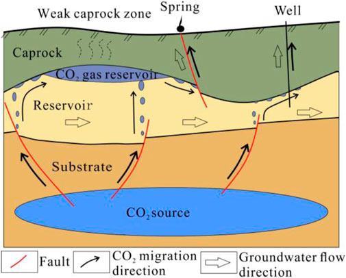
FIGURE 9. CO2 leakage pattern diagram of Qinghai Ping’an.
Self-sealing effect due to CO2 leakage
Travertine self-sealing refers to the hydrothermal alteration or precipitation of minerals contained in underground hot water in some previously uncapped reservoirs, which can transform the overlying high-permeability geological structures into low-permeability ones. The formed travertine cemented rock layer can act as a caprock due to its low permeability, isolating the deep fluid from the surface.
The formation of travertine is mainly because the partial pressure of CO2 in the water is higher than surrounding atmosphere, so that CO2 escapes from the water, and the carbonate in the water is supersaturated and precipitated. The reaction formula of travertine formation is shown in Eq. 1.
The chemical precipitation in Bing Lingshan spring is obvious, indicating that Ca2+ and HCO3- in groundwater are in a supersaturated state. Due to the change of pressure, the leakage channel of CO2 meets the conditions of travertine self-sealing.
Numerical simulation results show that the CO2-rich fluid migrates from the reservoir to the surface along the fracture, and the CO2 partial pressure decreases in the process, resulting in the dissolution of gypsum and the precipitation of calcite in the fracture channel. During the process of migration to the surface, the dissolution and precipitation rates gradually increase. At the surface, 0.5644 g of gypsum can be dissolved per kilogram of fluid, and 0.9030 g of calcite can be precipitated. Set the density of gypsum to be 2.31 g/cm3 and the density of calcite to be 2.71 g/cm3. The volume of calcite precipitated during this process is larger than the volume of dissolved gypsum.
In the surface position, each liter of fluid can fill the gap up to 0.088881 cm3, and in the 200 m deep crack, the gap can be filled by 0.04261 cm3 per liter of fluid. The single-width flow rate of the fissure is set to be 2 L/s, and the top of the 0.3 m wide fissure is the first to complete self-sealing, which takes 390.66 days; and it took 814.89 days for the bottom of the fissure to finally complete self-sealing.
According to the flow monitoring of Bing Lingshan spring, the gas-liquid ratio of the fluid is about 0.8. It is speculated that when the 0.3 m-wide crack is completely self-sealing, the leakage of CO2 from a single-width crack is about 140,813.3 m3. Under the condition of 1 atm and a temperature of 25°C, the CO2 density is 1.7845 kg/m3, and the mass of CO2 leaked from a single-width crack is about 251.28 tons.
Conclusion
1) The natural CO2 leakage mechanism in Qinghai Ping’an is as follows: the deep carbonate minerals in the crust are decomposed at high temperature to generate CO2, and the generated CO2 rises into the reservoir along with the deep and large fault. Blocked by the caprock, CO2 accumulates at the top of the reservoir, and then migrates to the leakage channel with the groundwater flow, and finally leaks to the surface.
2) Several vertical travertine veins can be seen in the section of the ancient travertine platform of Bing Lingshan in Ping’an County, Qinghai Province. They are formed by mineral precipitation from the CO2-rich water in the water-conducting fissures, which confirms the existence of the self-sealing effect of the caprock. The microscopic morphology and geochemical characteristics show that the fractures have experienced 4 times of self-sealing, corresponding to four tectonic events.
3) Based on the hydrochemical analysis and geological observation data, the hydrogeochemistry numerical simulation was carried out. The results show that: first, gypsum dissolves and calcite precipitates during the migration of CO2-rich water to the surface, and the closer to the surface, the faster the dissolution and precipitation rate; 2nd, self-sealing occurs during the migration of CO2-rich water to the surface, and the closer to the surface, the more significant the self-sealing effect is. The single-width flow rate of the fracture is set to 2 L/s. The top of the fracture is the first to complete self-sealing, which takes 390.66 days; and the bottom of the fracture is finally self-sealing, which takes 814.89 days; 3rd, according to the flow monitoring of Bing Lingshan spring, the gas-liquid ratio of the fluid is about 0.8. It is speculated that when the 0.3 m wide fissure achieves complete self-sealing, the leakage of CO2 from a single wide fissure is about 140,813.3 m3, or about 251.28 tons.
Data availability statement
The original contributions presented in the study are included in the article/supplementary material, further inquiries can be directed to the corresponding authors.
Author contributions
LF: Conceptualization, Methodology, Investigation, Funding acquisition. YD: Investigation, Writing—Original Draft. CZ: Resources, Methodology, Funding acquisition. XM: Software, Formal analysis, Visualization. TL: Supervision. XJ: Project administration. WS: Data Curation.
Funding
This research was funded by the, 2020 Qinghai Province “Kunlun Talents” Action Plan (青人才字[2020]18号), 2021 “High-level Talent Project” of Bureau of Geological Exploration and Development of Qinghai Province (青地矿科[2021]16号), Qinghai Province Science and Technology Application Basic Research Project under Grant No. 2022-ZJ-735, and China Geological Survey Project under Grant No. DD20221818.
Conflict of interest
The authors declare that the research was conducted in the absence of any commercial or financial relationships that could be construed as a potential conflict of interest.
Publisher’s note
All claims expressed in this article are solely those of the authors and do not necessarily represent those of their affiliated organizations, or those of the publisher, the editors and the reviewers. Any product that may be evaluated in this article, or claim that may be made by its manufacturer, is not guaranteed or endorsed by the publisher.
References
Anelia, P., Adrian, C., Corinne, L., Martin, F., Noirez, S., Brichart, T., et al. (2021). Aquifer-CO2 leak project: physicochemical characterization of the CO2 leakage impact on a carbonate shallow freshwater aquifer-sciencedirect. Int. J. Greenh. Gas Control 106, 103231. doi:10.1016/j.ijggc.2020.103231
Choi, B. Y. (2019). Potential impact of leaking CO2 gas and CO2-rich fluids on shallow groundwater quality in the chungcheong region (South Korea): A hydrogeochemical approach[J]. Int. J. Greenh. Gas Control 84, 13–28. doi:10.1016/j.ijggc.2019.03.010
Cui, Zhendong, Liu, Da’an, Zeng, Rongshu, et al. (2011). Potential geological and environmental risks and its prevention measures for CO2 geological storage projects. Geol. Rev. 57 (5), 700–706. ( in Chinese with English abstract).
Delkhahi, B., Nassery, H. R., Vilarrasa, V., Alijani, F., and Ayora, C. (2020). Impacts of natural CO2 leakage on groundwater chemistry of aquifers from the Hamadan Province, Iran. Int. J. Greenh. Gas Control 96, 103001. doi:10.1016/j.ijggc.2020.103001
Do, H. K., Yu, S., Ryuh, Y. G., Ju, Y., Kang, H. J., Ha, S. W., et al. (2022). Tracing CO2 leakage and migration using the hydrogeochemical tracers during a controlled CO2 release field test. Appl. Geochem. 143, 105390. doi:10.1016/j.apgeochem.2022.105390
Erik, L., Per, B., Malin, T., and Grimstad, A. A. (2017). Aliso canyon leakage as an analogue for worst case CO2 leakage and quantification of acceptable storage loss. Energy Procedia 114, 4279–4286. doi:10.1016/j.egypro.2017.03.1914
Fu, Lei, Zhang, S., Jia, X., Shengtao, Li., and Tao, Y. (2019). Test of the paleoenvironment reconstruction of bingling hill travertine in large time scale. Quat. Sci. 39 (2), 510–517. doi:10.11928/j.issn.1001-7410.2019.02.22
Gal, F., Proust, E., Humez, P., Braibant, G., Brach, M., Koch, F., et al. (2013). Inducing a CO2 leak into a shallow aquifer (CO2 Field Lab EUROGIA+project): Monitoring the CO2 plume in groundwaters. Energy Procedia 37, 3583–3593. doi:10.1016/j.egypro.2013.06.251
Gale, J. (2004). Geological storage of CO2: what do we know, where are the gaps and what more needs to be done? Energy 29, 1329–1338. doi:10.1016/j.energy.2004.03.068
Gupta, Pankaj Kumar, and Yadav, Basant (2020). Leakage of CO2 from geological storage and its impacts on fresh soil–water systems: a review. Environ. Sci. Pollut. Res. 27, 12995–13018. doi:10.1007/s11356-020-08203-7
Ha, S. W., Park, B. H., Lee, S. H., and Lee, K. K. (2017). Experimental and numerical study on gaseous CO2 leakage through shallow-depth layered porous medium: implication for leakage detection monitoring. Energy Procedia 114, 3033–3039. doi:10.1016/j.egypro.2017.03.1431
Jefferson, M. (2015). IPCC fifth assessment synthesis report: "climate change 2014: longer report": critical analysis. Technol. Forecast. Soc. Change 92 (3), 362–363. doi:10.1016/j.techfore.2014.12.002
Johnson, G., Hicks, N., Bond, C. E., Gilfillan, S., Jones, D., Kremer, Y., et al. (2017). Detection and understanding of natural CO2 releases in KwaZulu-Natal, South Africa. Energy Procedia 114, 3757–3763. doi:10.1016/j.egypro.2017.03.1505
Jonathan, P., Dave, J., Jerry, B., Beaubien, S., Foekema, E., Gemeni, V., et al. (2014). A guide for assessing the potential impacts on ecosystems of leakage from CO2 storage sites. Energy Procedia 63, 3242–3252. doi:10.1016/j.egypro.2014.11.351
Jones, D. G., Barkwitha, A. K. A. P., Hannis, S., Lister, T., Gal, F., Graziani, S., et al. (2014). Monitoring of near surface gas seepage from a shallow injection experiment at the CO2 Field Lab, Norway-ScienceDirect. Int. J. Greenh. Gas Control 28 (2), 300–317. doi:10.1016/j.ijggc.2014.06.021
Karas, D., Demić, I., Kultysheva, K., Antropov, A., Blagojevic, M., Neele, F., et al. (2016). First field example of remediation of unwanted migration from a natural CO2 reservoir: the bečej field, Serbia. Energy Procedia 86, 69–78. doi:10.1016/j.egypro.2016.01.008
Li, Xiaochun, Hitoshi, Koide, and Takashi, Ohsumi (2003). CO2 aquifer storage and the related rock mechanics issues. Chin. J. Rock Mech. Eng. 22 (6), 989–994. ( in Chinese with English abstract).
Ma, D., Gao, J., Gao, Z., Jiang, H., Zhang, Z., and Xie, J. (2020). Gas leakage recognition for CO2 geological sequestration based on the time series neural network-ScienceDirect. Chin. J. Chem. Eng. 28 (9), 2343–2357. doi:10.1016/j.cjche.2020.06.014
Mark, L. P., Michael, P., Rajesh, P., and Illangasekare, T. (2014). CO2 leakage into shallow aquifers: modeling CO2 gas evolution and accumulation at interfaces of heterogeneity. Energy Procedia 63, 3253–3260. doi:10.1016/j.egypro.2014.11.352
Melis, C., Jonathan, M. B., Mark, E. V., Gernon, T. M., Wright, I. C., and Long, D. (2015). Gas migration pathways, controlling mechanisms and changes in sediment acoustic properties observed in a controlled sub-seabed CO2 release experiment. Int. J. Greenh. Gas Control 38, 26–43. doi:10.1016/j.ijggc.2015.03.005
Qafoku, N. P., Lawter, A. R., Bacon, D. H., Zheng, L., Kyle, J., and Brown, C. F. (2017). Review of the impacts of leaking CO2 gas and brine on groundwater quality. Earth-Science Rev. 169, 69–84. doi:10.1016/j.earscirev.2017.04.010
Ren, S., Li, D., Zhang, L., and Huang, H. (2014). Leakage pathways and risk analysis of CO2 in geologic storage. Acta Pet. Sin. 35 (3), 591–601. ( in Chinese with English abstract). doi:10.7623/syxb201403024
Roberts, J. J., Laplastrier, A., Shipton, Z. K., Bell, A. F., and Karolyte, R. (2019). Structural controls on the location and distribution of CO2 emission at a natural CO2 spring in Daylesford, Australia. Int. J. Greenh. Gas Control 84, 36–46. doi:10.1016/j.ijggc.2019.03.003
Saleem, U., Dewar, M., Tariq, N. C., Sana, M., Lichtschlag, A., Alendal, G., et al. (2021). Numerical modelling of CO2 migration in heterogeneous sediments and leakage scenario for STEMM-CCS field experiments. Int. J. Greenh. Gas Control 109, 103339. doi:10.1016/j.ijggc.2021.103339
Schroder, I. F., Wilson, P., Feitz, A. F., and Ennis-King, J. (2017). Evaluating the performance of soil flux surveys and inversion methods for quantification of CO2 leakage. Energy Procedia 114, 3679–3694. doi:10.1016/j.egypro.2017.03.1499
Susan, A. C., Elizabeth, K., Kayyum, M., Dai, Z., Sun, Y., Trainor-Guitton, W., et al. (2014). Key factors for determining groundwater impacts due to leakage from geologic carbon sequestration reservoirs. Int. J. Greenh. Gas Control 29, 153–168. doi:10.1016/j.ijggc.2014.07.007
Taylor, Peter, Stahl, H., Toberman, M., Sayer, M. D., Reynolds, A., Sato, T., et al. (2015). Impact and recovery of pH in marine sediments subject to a temporary CO2 leak. Int. J. Greenh. Gas Control 38, 93–101. doi:10.1016/j.ijggc.2014.09.006
Vialle, S., Druhan, J. L., and Maher, K. (2016). Multi-phase flow simulation of CO2 leakage through a fractured caprock in response to mitigation strategies. Int. J. Greenh. Gas Control 44, 11–25. doi:10.1016/j.ijggc.2015.10.007
Xiao, T., Wang, B., Xu, L., Esser, R., Dai, Z., Cather, M., et al. (2022). Underground sources of drinking water chemistry changes in response to potential CO2 leakage. Sci. Total Environ. 847, 157254. doi:10.1016/j.scitotenv.2022.157254
Xie, Jian, Ning, Wei, Wu, Zhouli, et al. (2017). Progress in leakage study of geological CO2 storage. Rock Soil Mech. 38, 181–188. doi:10.16285/j.rsm.2017.S1.021
Xu, Zhigang, Chen, Daizhao, and Zeng, Rongshu (2008). The leakage risk assessment and remediation options of CO2 geological storage. Geol. Rev. 54 (3), 373. doi:10.16509/j.georeview.2008.03.014
Zahasky, C., and Benson, S. M. (2016). Evaluation of hydraulic controls for leakage intervention in carbon storage reservoirs. Int. J. Greenh. Gas Control 47, 86–100. doi:10.1016/j.ijggc.2016.01.035
Zhai, X., Ge, H., Chen, X., Xu, Y., and Fan, G. (2018). The influence of CO2 leaking on environmental monitoring in the process of CO2 geological sealing. Energy Procedia 153, 207–214. doi:10.1016/j.egypro.2018.10.034
Keywords: geological CO2 storage, CO2 leakage, self-sealing, travertin, Ping’an
Citation: Fu L, Diao Y, Zheng C, Ma X, Zhang C, Liu T, Jin X and Shao W (2022) Caprock self-sealing effect due to CO2 leakage from geologic carbon sequestration reservoirs: a case study at Ping’an, China. Front. Energy Res. 10:955465. doi: 10.3389/fenrg.2022.955465
Received: 30 May 2022; Accepted: 25 July 2022;
Published: 31 August 2022.
Edited by:
Greeshma Gadikota, Cornell University, United StatesCopyright © 2022 Fu, Diao, Zheng, Ma, Zhang, Liu, Jin and Shao. This is an open-access article distributed under the terms of the Creative Commons Attribution License (CC BY). The use, distribution or reproduction in other forums is permitted, provided the original author(s) and the copyright owner(s) are credited and that the original publication in this journal is cited, in accordance with accepted academic practice. No use, distribution or reproduction is permitted which does not comply with these terms.
*Correspondence: Lei Fu, ZnVsZWlAbWFpbC5jZ3MuZ292LmNu; Changyuan Zheng, NTYyOTUxNThAcXEuY29t