 Qian Miao
 Yang Liu*
- Harbin Institute of Technology, Harbin, China
The performance of the actuator is becoming increasingly important in the ultra-precision stage. However, the traditional Lorentz motors with given mechanical parameters cannot provide enough force for the next-generation motion stage in the semiconductor industry since they achieve a physical limit of power factor. To tackle this problem, this study develops a novel-driven approach and its control strategy for high-dynamic stages. Explicitly, the proposed method utilizes a linear reluctance motor as an actuator, which could promote the continuous thrust significantly. A heuristic optimization-based Bouc–Wen model is established to describe the nonlinear behavior of the novel actuator. Also, a flux control algorithm based on the integral sliding mode is derived and adjusted for precision thrust generation. Comparative simulations on a specific linear reluctance motor confirm the effectiveness and superiority of the proposed method and show that it has the ability to conquer the force nonlinearity of the novel actuator.
1 Introduction
To increase the throughput, the precision motion stage in lithography machine has to operate at high speed and high acceleration, which requires a lower moving mass or larger driven force (Boeren et al., 2020; Kuang et al., 2020; Huang et al., 2021; Voorhoeve et al., 2021; Kuang et al., 2022). Voice coil motor is widely used in nano-accuracy motion stages because of its advantages in high force linearity and low stiffness as contactless direct actuators (Song et al., 2018; Li L. et al., 2019; Liu et al., 2020; Song et al., 2022). However, this kind of actuator is reaching physical limits considering the maximum force to the equivalent load ratio and the corresponding copper loss ratio. Thus, it is not the best choice for driving the next-generation nano-positioning stage. For example, the reticle stage of a state-of-the-art photolithography scanner must accelerate at tens of g’s. Thus, actuators that deliver high force with high efficiency have to be developed.
Electromagnetic technology has been widely concerned because of its advantages of high output density (Xu et al., 2022a; Xu et al., 2022b), a new type of reluctance motor is proposed. Different from the Lorentz motor, the force of the reluctance motor is not linearly proportional but a square of the excitation current. So it could bring about larger force to current ratio and achieve significantly higher power densities and lower dissipations (Cigarini et al., 2020; Ito et al., 2020; Moya-Lasheras et al., 2020; Burgstaller et al., 2021; Moya-Lasheras et al., 2021; Al Saaideh et al., 2022). As a promising new candidate, the reluctance motor also brings various intractable issues. From the control point of view, it includes a variety of nonlinear problems, including the output force proportional to the square of the current, inversely proportional to the stroke of the motor, and the hysteresis effect with the multi-value rate. These strong nonlinearities make their control difficult and the force output of reluctance motors cannot be accurately predicted, thus limiting their application in nano motion stages. Among them, the force hysteresis caused by soft ferromagnetic materials is the most notable nonlinearity that has to be considered in precision applications (Cigarini et al., 2019). The idea of this paper is to deal with the multi-loop rate-related hysteresis nonlinearity of the reluctance motor through a smart method, that can achieve the purpose of high-precision control of the flux. This kind of nonlinearity is rarely discussed in permanent magnetic motors, but it exists in piezoelectric actuators widely and attracts lots of attention (Adriaens et al., 2000; Chen et al., 2017; Nie et al., 2022; Zhang et al., 2022). To describe the characteristics of hysteresis, various model structures are proposed. The most representative methods include physical modeling, mathematical operator modeling, and intelligent modeling (Li M. et al., 2019; Al Janaideh et al., 2021; Zhang et al., 2021; Cheng et al., 2022; Flores et al., 2022; Otieno et al., 2022). Specifically, the Bouc–Wen model sorted by the physical method is the most popular one since its parameters have definite physical meaning and are easily obtained (Ismail et al., 2009; Hassani et al., 2014). Once the mathematical expression of the hysteresis is obtained, the corresponding compensation algorithm can be developed. Among the existing methods, one of the most commonly used approaches is the inverse compensation. Qin proposed an adaptive hysteresis compensation method to solve the nonlinearity of PEAs at a high frequency for inexperienced users (Rakotondrabe, 2011). Micky presented an inverse multiplicative structure for the Bouc–Wen based model, reducing the computation load of the preexisting methods (Qin et al., 2022). Didace adopted the inverse Bouc–Wen model as feedforward controller, and the proposed compensation strategy was verified in a 3-DOF piezotube scanner (Habineza et al., 2015). Although the inverse compensation scheme is useful to reduce nonlinearity, a common drawback of this method is that a precise inverse model has to be constructed to counteract the effect of hysteresis. However, hysteresis usually contains more than one loop (Liu et al., 2016). Thus, the corresponding inverse model with high accuracy is hard to establish.
Different from the inverse compensation method, this paper treats hysteresis as a model uncertainty or a kind of internal disturbance, and develops a robust controller to obtain a precise force output from the reluctance motor. As a popular variable structure control algorithm, the sliding mode control (SMC) makes the system states move towards a predesigned sliding surface and then maintains their movement on the surface (Gu et al., 2015). Once the states reach the sliding surface, the system dynamics is determined by the sliding mode and has a certain robustness to the external disturbance and model variations. Since SMC is easy to implement in embedded systems, this paper will develop an SMC-based control strategy.
The rest of the paper is organized as follows: a novel precision motion stage driven by the linear reluctance motor is described in section 2, and the force performance is determined. Then, a Bouc–Wen model is established by using the simulation data and the heuristic algorithm to express the hysteresis relationship between magnetic flux B and current I in section 3. Based on the established model, an integral sliding mode controller is designed in section 4. Afterward, simulation studies were carried out in section 5, where PI with the inverse hysteresis compensation composite controller was used for comparison. Finally, section 6 concludes this research.
2 Working Principle and Requirement of Linear Reluctance Motor in the Nano-Positioning Stage
The nano-positioning stage in the lithography machine usually adopts a long-stroke and short-stroke combined structure. The positioning accuracy of the stage is ensured by the short-stroke module, while the long-stroke module provides a large motion range. During the scanning process, the short stroke and long stroke should move coordinately. So, the short-stroke stage also requires high acceleration as well as high accuracy. As mentioned in section 1, the linear reluctance motor is a novel candidate actuator in the IC manufacturing field. A testbed driven by a reluctance motor is designed and shown in Figure 1.
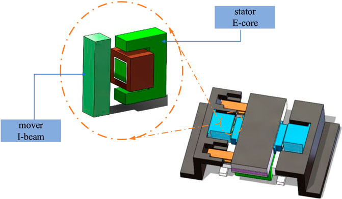
FIGURE 1. A sketch of the nano-positioning stage driven by the reluctance motor.
As seen from Figure 1, the mover I-beam installed on the motion stage is installed opposite to the stator part of the reluctance actuator. In practice, the two reluctance actuators are energized in turn, and an attractive force is generated between the stator E-core and the mover I-beam, which provides the thrust required for high acceleration. According to the magnetic simulation by COMSOL, the attractive reluctance force between the stator and the I-beam is determined by the magnetic field distribution in the air gap of the linear reluctance motor. As expected, most of the magnetic field distributes around the E-core. If the leakage flux is ignored, the reluctance force F exerted on the mover is described by the following equations:
where µ0 denotes the permeability of air, N denotes the number of coil turns at the center of the E-core, A denotes the area, and g denotes the air gap. It is a lumped model which disregards flux leakage, fringing, and saturation.
The linear reluctance motor is driven by the power amplifier. The current command could be derived from Eq. 3 as
Because the features printed on the IC can be as small as tens of nanometers, the position accuracy of the reticle and wafer during exposure must be accurate to a few nanometers or better. The servo bandwidth is limited by stage dynamics, so the majority of the position accuracy comes from the force feedforward accuracy, which must be better than 99.9% accurate for a typical trajectory (Ian, 2015). Therefore, the fluctuation range of the force must be within the range of 0.1%. Further, the force F is proportional to the square of the magnetic flux B, as shown in Eq. 3. So the fluctuation range of the magnetic flux is defined as 0.316%. Therefore, when the reluctance actuator is controlled by magnetic flux feedback, the error is limited to 0.316%, which can meet the requirements.
3 Hysteresis Model
3.1 Bouc–Wen Model
The Bouc–Wen model was proposed in 1976 and is widely used for describing hysteresis nonlinearity because of its advantages of simple structure and few parameters to be identified. At present, the model is expressed as follows:
where x(t) is the state variable of the system and B(t) is the output flux,
3.2 Parameter Identification of Hysteresis Loop
Due to the nonlinearity, it is still a challenge to determine the parameters in the Bouc–Wen model. As an intelligent optimization algorithm, the teaching-learning-based optimization (TLBO) is a preferred method. According to Eq. 5, the parameters to be identified are defined by the vector
where
where N is the total number of samples,
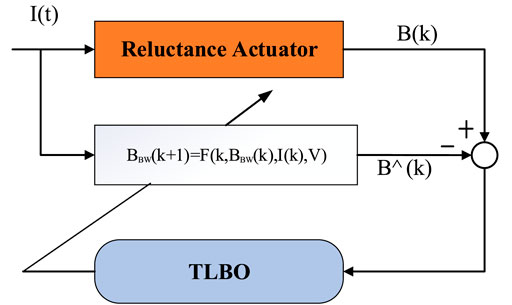
FIGURE 2. The schematic diagram of Bouc–Wen model identification.
The process of model construction is carried out offline as follows:
(1) Data collection: The simulation data including output flux and input current of reluctance motors are obtained by multiphysics simulation software COMSOL.
(2) Model implementation: The Bouc–Wen model is constructed in the Maltab/Simulink, as shown in Figure 3.
(3) Parameter identification: The simulation data are loaded, and then the model parameters are optimized by the TLBO.
(a) The dynamic model for the linear reluctance motor.
(b) Bouc–Wen model implemented with the Maltab/Simulink block.
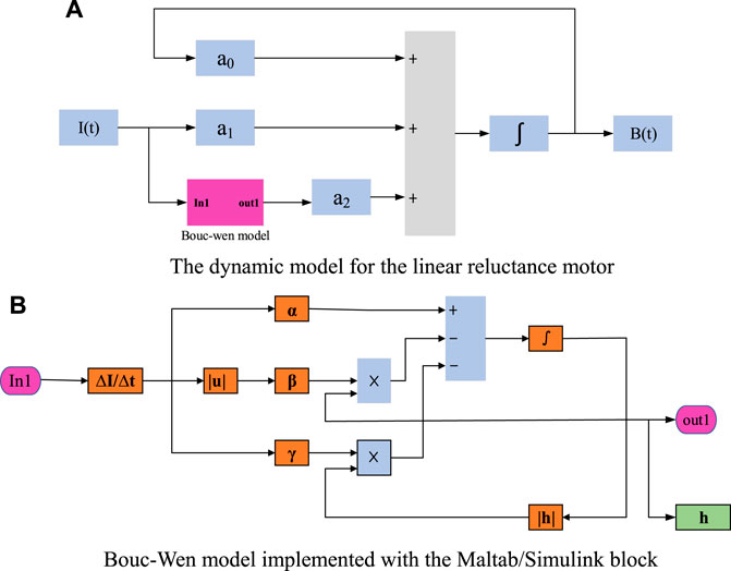
FIGURE 3. Dynamic simulation model implemented with Matlab/Simulink.
4 Controller Design of the Reluctance Motor
In this article, we adopt the variable structure control method to solve the nonlinear problem in the reluctance motor caused by hysteresis. Without considering external disturbances, it is assumed that the established Bouc–Wen model can accurately describe the hysteresis characteristics of the reluctance motor. To reduce the adjusting effort of PID, a control algorithm based on the integral sliding mode has been developed.
In the design of the sliding mode controller, the dynamic performance of the system is determined by the sliding mode surface. The sliding mode surface with integral term is widely used since it can effectively eliminate the steady-state error and improve the robustness of the controller. Therefore, an integral–derivative type of sliding surface is defined as follows:
where
Considering the system described by Eq. 5 and the sliding mode expressed by Eq. 8, if the controller
where
A Lyapunov function is adopted to verify the stability of the closed-loop control system, which is shown as
Then, taking the time derivative of the sliding function Eqs. 8, 11:
Substituting Eq. 12 into Eq. 13 and taking consider of the control input Eq. 5, it leads to
Finally, taking the designed sliding mode control rate Eq. 10 into Eq. 14,
In order to reduce the jitter of the sliding mode control system during the control process, the saturation function sat ( ) was adopted to replace the sign function sgn ( ).
where
5 Simulation
To verify the feasibility of substituting voice coil motors with reluctance motors, a testbed is designed according to the desired performance. A prototype of a reluctance motor with specified parameters is designed and tested in COMSOL, and the exported data is used to construct the motor model.
To establish the model of the reluctance motor, the Bouc–Wen structure is selected and the corresponding coefficients are obtained by TLBO. The parameters needed in the optimization is set as Table 1:
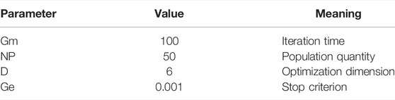
TABLE 1. Set parameters of the TLBO.
The identification results are listed in Table 2. Comparing the actual data and the fitting data using the estimated Bouc–Wen model, the curves are depicted in Figure 4. Due to the model error, the maximal mismatching deviation is 0.005333.
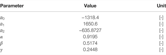
TABLE 2. Identified parameters of the classical Bouc–Wen model.
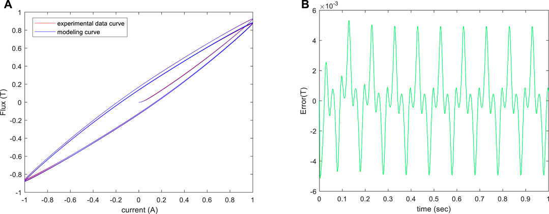
FIGURE 4. (A) Hysteresis loop obtained by experiments and the identified Bouc–Wen model. (B) Bouc–Wen model error respect to experimental data.
In the simulation, it adopts the flux trajectory as the reference input directly, expressed as

TABLE 3. Parameters of ISMC.
For comparison, the combined strategy of PI controller and inverse model compensation is selected. The schematic diagram is shown in Figure 5 and the relevant parameters are shown in Table 4.
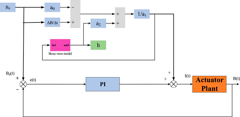
FIGURE 5. The schematic diagram of the combined strategy of PI controller and inverse model compensation.

TABLE 4. Parameters of contrastive controller.
With the proposed ISMC, the output of the simulated reluctance motor is shown in Figure 6A. As seen from Figure 6B, the width of the hysteresis loop has been reduced, which means that the hysteresis effect has been compensated significantly. In addition, Figure 6C depicted the sliding variable, implying that the sliding surface is maintained within the boundary layer ∆ (i.e., 0.1). Moreover, the control signal is described in Figure 6D. Obviously, there is no chattering in the designed controller.
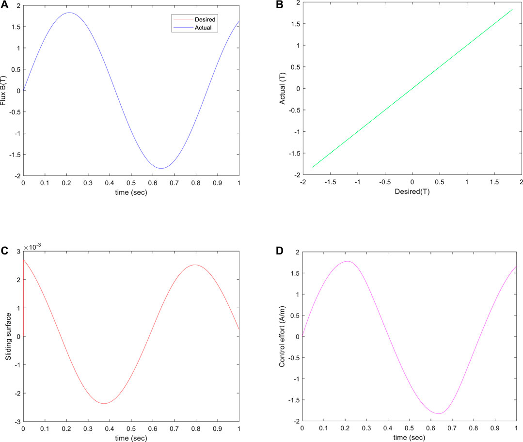
FIGURE 6. Sinusoidal Trajectory Tracking Results of an Integral Sliding Mode Controller. (A) Desired and actual flux trajectories. (B) Actual versus desired flux. (C) Sliding surface variable. (D) Control effort of the controller.
The flux tracking error results between the input Bd and output B with the two controllers are compared in Figure 7. As seen from Figures 7B,D,F the performance of the proposed ISMC is superior to that of both conventional PI controllers and combined controllers with PI and feedforward hysteresis compensation in terms of tracking errors. When using a PI controller, the flux tracking error ranges from −0.0041T to 0.0056 T. Therefore, the required magnetic flux requirements can not be met. When using PI and hysteresis inverse model compensation control, the flux tracking error ranges from −0.000395T to 0.0029 T. Although inverse hysteresis compensation is employed to counteract the nonlinearity, whereas, when using the proposed ISMC, flux tracking error substantially reduces from 6.287e-06 T– to 0.0027 T. Compared with the combined controller, the error is not only small in amplitude but also has a more stable change trend. Therefore, the integral sliding mode controller has better robustness.
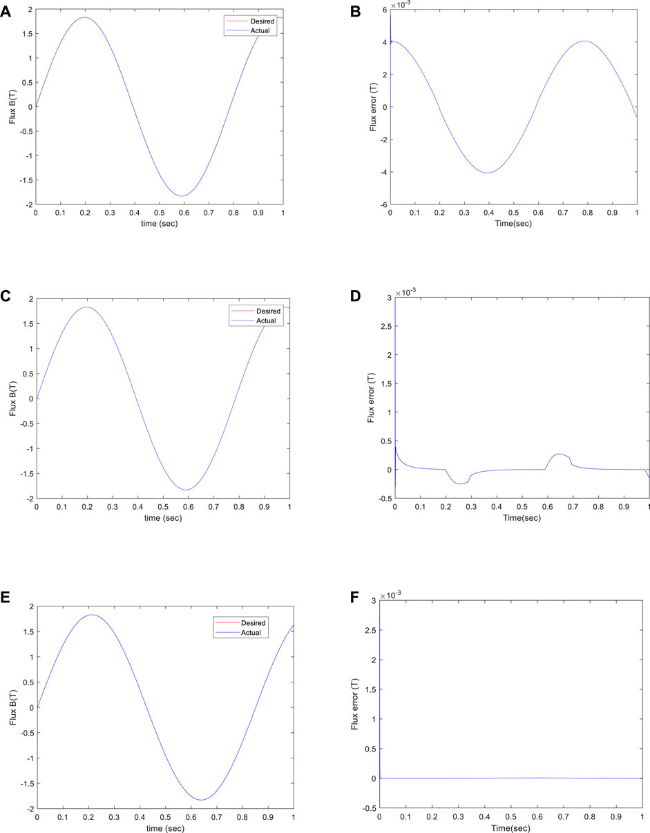
FIGURE 7. Sinusoidal motion tracking results of (A),(B) pure PI, (C),(D) PI and inverse model compensation compound control, and (E),(F) ISMC.
In order to explore the influence of different controllers on the flux tracking performance, the error data obtained by the simulation is analyzed, and the average value, maximum value, and standard deviation of the magnetic flux error under different controllers are obtained. The analysis results are shown in Table 5.

TABLE 5. Control performance of different controllers.
When using different feedback controllers, the tracking error of the magnetic flux is shown in Figure 7 and described in Table 5. When using the integral sliding mode controller, compared with the PI controller and the inverse model compensation joint control, the mean, maximum, and standard deviation of the flux tracking errors are reduced by 99.3%, 6.9%, and 68.19%, respectively. Hence, compared with the PI controller and the PI and hysteresis inverse model compensation controller it can be seen that the flux with Integral Sliding Mode Control has better tracking performance and robustness.
6 Conclusion and Discussion
In this paper, the reluctance actuator driven nano-positioning stage was designed and the precision motion control scheme with ISMC was applied. Based on the Bouc–Wen model identified by experimental data and TLBO, the ISMC was designed and the hysteresis characteristics of the reluctance actuator is treated as the internal disturbance. The simulation results show that the proposed method is effective in overcoming the hysteresis without accurate parameters and it is promising in high-precision control applications.
This paper also provides a technical solution in other precision machine tools and related equipment with hysteresis.
Data Availability Statement
The original contributions presented in the study are included in the article/Supplementary Material; further inquiries can be directed to the corresponding author.
Author Contributions
YL conceived and designed the simulations; QM performed the simulations; QM analyzed the data; and JBT contributed the investigated stage.
Conflict of Interest
The authors declare that the research was conducted in the absence of any commercial or financial relationships that could be construed as a potential conflict of interest.
Publisher’s Note
All claims expressed in this article are solely those of the authors and do not necessarily represent those of their affiliated organizations, or those of the publisher, the editors, and the reviewers. Any product that may be evaluated in this article, or claim that may be made by its manufacturer, is not guaranteed or endorsed by the publisher.
References
Adriaens, H. J. M. T. S., de Koning, W. L., and Banning, R. (2000). Modeling Piezoelectric Actuators. IEEE/ASME Trans. Mechatron. 5 (4), 331–341. doi:10.1109/3516.891044
Al Janaideh, M., Xu, R., and Tan, X. (2021). Adaptive Estimation of Play Radii for a Prandtl-Ishlinskii Hysteresis Operator. IEEE Trans. Contr. Syst. Technol. 29 (6), 2687–2695. doi:10.1109/TCST.2020.3046019
Al Saaideh, M., Alatawneh, N., and Al Janaideh, M. (2022). Design Parameters of a Reluctance Actuation System for Stable Operation Conditions with Applications of High-Precision Motions in Lithography Machines. IET Electr. Power Appl. 16 (1), 68–85. doi:10.1049/elp2.12135
Boeren, F., Lanzon, A., and Oomen, T. (2020). Iterative Identification and Control Using Non-Normalized Coprime Factors With Application in Wafer Stage Motion Control. IEEE Trans. Contr. Syst. Technol. 28 (2), 413–424. doi:10.1109/TCST.2018.2877680
Burgstaller, I., Ito, S., Fujimoto, H., and Schitter, G. (2021). “Development of Reluctance Actuator for High-Precision Positioning and Scanning Motion,” in IEEE ELECTR, NETWORK: IEEE, Kashiwa, Japan, 09 March 2021.
Chen, Q.-S., Xu, Y.-L., Yang, X.-F., and Li, X.-P. (2017). The Identification of Reluctance Actuators B-H Hysteresis Model Using Teaching-Learning-Based Optimization. Jinan, China: IEEE.
Cheng, L., Chen, W., and Tian, L. (2022). A Modified Direct Inverse Prandtl-Ishlinskii Model Based on Two Sets of Operators for the Piezoelectric Actuator Hysteresis Compensation. Int. J. Of Appl. Electromagn. And Mech. 68 (2), 177–191. doi:10.3233/JAE-210072
Cigarini, F., Csencsics, E., Schlarp, J., Ito, S., and Schitter, G. (2020). Multiphysics Finite Element Model for the Computation of the Electro-Mechanical Dynamics of a Hybrid Reluctance Actuator. Math. And Comput. Model. Of Dyn. Syst. 26 (4), 322–343. doi:10.1080/13873954.2020.1766509
Cigarini, F., Ito, S., Konig, J., Sinn, A., and Schitter, G. (2019). Compensation of Hysteresis in Hybrid Reluctance Actuator for High-Precision Motion. IFAC-PapersOnLine 52 (15), 477–482. doi:10.1016/j.ifacol.2019.11.721
Flores, G., Aldana, N., and Rakotondrabe, M. (2022). Model Predictive Control Based on the Generalized Bouc-Wen Model for Piezoelectric Actuators in Robotic Hand With Only Position Measurements. IEEE Control Syst. Lett. 6, 2186–2191. doi:10.1109/LCSYS.2021.3136456
Gu, G.-Y., Zhu, L.-M., Su, C.-Y., Ding, H., and Fatikow, S. (2015). Proxy-Based Sliding-Mode Tracking Control of Piezoelectric-Actuated Nanopositioning Stages. IEEE/ASME Trans. Mechatron. 20 (4), 1956–1965. doi:10.1109/TMECH.2014.2360416
Habineza, D., Rakotondrabe, M., and Le Gorrec, Y. (2015). Bouc–Wen Modeling and Feedforward Control of Multivariable Hysteresis in Piezoelectric Systems: Application to a 3-DoF Piezotube Scanner. IEEE Trans. Contr. Syst. Technol. 23 (5), 1797–1806. doi:10.1109/TCST.2014.2386779
Hassani, V., Tjahjowidodo, T., and Do, T. N. (2014). A Survey on Hysteresis Modeling, Identification and Control. Mech. Syst. And Signal Process. 49 (1-2), 209–233. doi:10.1016/j.ymssp.2014.04.012
Huang, W.-C., Yang, K.-M., and Zhu, Y. (2021). MIMO Data-Driven Feedforward Tuning for the Ultra-precision Wafer Stage Using Rational Basis Functions. Yantai, China: Springer.
Ian, R.- I.- M. (2015). Design and Control Methods for High-Accuracy Variable Reluctance Actuators. Ph.D. Diss. Mass. Inst. Technol. https://www.researchgate.net/publication/286079747_Design_and_control_methods_for_high-accuracy_variable_reluctance_actuators.
Ismail, M., Ikhouane, F., and Rodellar, J. (2009). The Hysteresis Bouc-Wen Model, a Survey. Arch. Comput. Methods Eng. 16 (2), 161–188. doi:10.1007/s11831-009-9031-8
Ito, S., Cigarini, F., and Schitter, G. (2020). Flux-Controlled Hybrid Reluctance Actuator for High-Precision Scanning Motion. IEEE Trans. Ind. Electron. 67 (11), 9593–9600. doi:10.1109/TIE.2019.2952829
Kuang, Z., Sun, L., Gao, H., and Tomizuka, M. (2020). Precise Motion Control of Wafer Stages via Adaptive Neural Network and Fractional-Order Super-twisting Algorithm. IFAC-PapersOnLine 53 (2), 8315–8320. doi:10.1016/j.ifacol.2020.12.1898
Kuang, Z., Sun, L., Gao, H., Tomizuka, M., and Tomizuka, M. (2022). Practical Fractional-Order Variable-Gain Supertwisting Control With Application to Wafer Stages of Photolithography Systems. IEEE/ASME Trans. Mechatron. 27 (1), 214–224. doi:10.1109/TMECH.2021.3060731
Li, L., Liu, Y., Li, L., and Tan, J. (2019). Kalman-Filtering-Based Iterative Feedforward Tuning in Presence of Stochastic Noise: With Application to a Wafer Stage. IEEE Trans. Ind. Inf. 15 (11), 5816–5826. doi:10.1109/TII.2019.2906331
Li, M., Wang, Q., Li, Y., and Jiang, Z. (2019). Modeling and Discrete-Time Terminal Sliding Mode Control of a DEAP Actuator with Rate-dependent Hysteresis Nonlinearity. Appl. Sci. 9 (13), 2625. doi:10.3390/app9132625
Liu, J.-B., and Zhou, K.-M. (2016). Neural Networks Based Modeling and Robust Control of Hysteresis. Chengdu, China: IEEE.
Liu, Y., Li, L., Yang, X., and Tan, J. (2020). Enhanced Kalman-Filtering Iterative Learning Control with Application to a Wafer Scanner. Inf. Sci. 541, 152–165. doi:10.1016/j.ins.2020.05.125
Moya-Lasheras, E., Sagues, C., and Llorente, S. (2021). An Efficient Dynamical Model of Reluctance Actuators with Flux Fringing and Magnetic Hysteresis. Mechatronics 74, 102500. doi:10.1016/j.mechatronics.2021.102500
Moya-Lasheras, E., and Sagues, C. (2020). Run-to-Run Control With Bayesian Optimization for Soft Landing of Short-Stroke Reluctance Actuators. IEEE/ASME Trans. Mechatron. 25 (6), 2645–2656. doi:10.1109/TMECH.2020.2987942
Nie, L., Luo, Y., Gao, W., and Zhou, M. (2022). Rate-dependent Asymmetric Hysteresis Modeling and Robust Adaptive Trajectory Tracking for Piezoelectric Micropositioning Stages. Nonlinear Dyn. 108 (3), 2023–2043. doi:10.1007/s11071-022-07324-7
Otieno, L. O., Nguyen, T. T., Park, S. J., Lee, Y. J., and Alunda, B. O. (2022). Feedforward Compensation for Hysteresis and Dynamic Behaviors of a High-Speed Atomic Force Microscope Scanner. J. Korean Phys. Soc. 80 (4), 325–336. doi:10.1007/s40042-021-00376-9
Qin, Y., Duan, H., and Han, J. (2022). Direct Inverse Hysteresis Compensation of Piezoelectric Actuators Using Adaptive Kalman Filter. IEEE Trans. Ind. Electron. 69 (9), 9385–9395. doi:10.1109/TIE.2021.3114741
Rakotondrabe, M. (2011). Bouc-Wen Modeling and Inverse Multiplicative Structure to Compensate Hysteresis Nonlinearity in Piezoelectric Actuators. IEEE Trans. Autom. Sci. Eng. 8 (2), 428–431. doi:10.1109/TASE.2010.2081979
Song, F., Liu, Y., Jin, W., Tan, J., and He, W. (2022). Data-Driven Feedforward Learning With Force Ripple Compensation for Wafer Stages: A Variable-Gain Robust Approach. IEEE Trans. Neural Netw. Learn. Syst. 33 (4), 1594–1608. doi:10.1109/TNNLS.2020.3042975
Song, F., Liu, Y., Xu, J.-X., Yang, X., He, P., and Yang, Z. (2018). Iterative Learning Identification and Compensation of Space-Periodic Disturbance in PMLSM Systems With Time Delay. IEEE Trans. Ind. Electron. 65 (9), 7579–7589. doi:10.1109/TIE.2017.2777387
Voorhoeve, R., de Rozario, R., Aangenent, W., and Oomen, T. (2021). Identifying Position-dependent Mechanical Systems: A Modal Approach Applied to a Flexible Wafer Stage. IEEE Trans. Contr. Syst. Technol. 29 (1), 194–206. doi:10.1109/TCST.2020.2974140
Xu, S., Liu, J., Yang, C., Wu, X., and Xu, T. (2021). A Learning-Based Stable Servo Control Strategy Using Broad Learning System Applied for Microrobotic Control. IEEE Trans. Cybern., 1–11. doi:10.1109/TCYB.2021.3121080
Xu, T., Huang, C., Lai, Z., and Wu, X. (2022a). Independent Control Strategy of Multiple Magnetic Flexible Millirobots for Position Control and Path Following. IEEE Trans. Robot., 1–13. doi:10.1109/TRO.2022.3157147
Xu, T., Hao, Z., Huang, C., Yu, J., Zhang, L., and Wu, X. (2022b). Multimodal Locomotion Control of Needle-like Microrobots Assembled by Ferromagnetic Nanoparticles. IEEE/ASME Trans. Mechatron., 1–12. doi:10.1109/TMECH.2022.3155806
Zhang, Q., Gao, Y., Li, Q., and Yin, D. (2021). Adaptive Compound Control Based on Generalized Bouc-Wen Inverse Hysteresis Modeling in Piezoelectric Actuators. Rev. Of Sci. Instrum. 92 (11), 115004. doi:10.1063/5.0059368
Keywords: reluctance actuator, Bouc–Wen model, flux control, integral sliding mode control, TLBO (teaching–learning-based optimization)
Citation: Miao Q, Liu Y and Tan JB (2022) Precision Flux Control of Linear Reluctance Actuator Using the Integral Sliding Mode Method. Front. Energy Res. 10:949782. doi: 10.3389/fenrg.2022.949782
Received: 21 May 2022; Accepted: 17 June 2022;
Published: 19 August 2022.
Edited by:
Yuanjun Guo, Shenzhen Institutes of Advanced Technology (CAS), ChinaReviewed by:
Shubo Wang, Qingdao University, ChinaShaojun Gan, Beijing University of Technology, China
Liu Yuan, Sun Yat-sen University, China
Copyright © 2022 Miao, Liu and Tan. This is an open-access article distributed under the terms of the Creative Commons Attribution License (CC BY). The use, distribution or reproduction in other forums is permitted, provided the original author(s) and the copyright owner(s) are credited and that the original publication in this journal is cited, in accordance with accepted academic practice. No use, distribution or reproduction is permitted which does not comply with these terms.
*Correspondence: Yang Liu, bGdoaXRAMTI2LmNvbQ==