 Alok Dhaundiyal
- Centre for Energy Research, Budapest, Hungary
This study pivoted on the flow behavior of air streams across solar air collectors provided with wooden baffles under the absorber plates. The two-pass system was used for both flat and finned surfaces. The von Kármán momentum integral and Blasius equations were solved with the help of PDPE and ODE45 techniques. The solution was assumed to be a part of the initial value problem (IVP). The energy analysis of both solar air collectors was carried out using the Hottel–Whillier–Bliss equation (HWB) equation. The Sankey diagram was used for energy distribution across the solar collectors. The gray box modeling approach was adopted to comprehend the airflow behavior across the channel. The objective of this study is to examine the intrinsic behavior of the proposed design. The displacement of boundary to compensate for the momentum of air stream (θt) decreased by 31.25%–62.50% with an increase in mass flow rate (
Introduction
A solar collector is a sort of energy exchanger that transforms solar energy either to increase the thermal energy of the working fluid for thermal applications or the electric energy via photovoltaic applications. For solar thermal applications, solar irradiation absorbed by a solar collector as heat energy is transferred to the working fluid (air, water, and oil). The heat extracted by the working fluid can be utilized for domestic heating or to charge a thermal reservoir during inclement weather conditions. Another function is the recovery of plenty of waste heat from a PV module by incorporating a PV board with recuperating channels filled with carrier fluids for miscellaneous thermal processes. Such collectors are often bifurcated into either non-concentrating and concentrating collectors. A non-concentrating collector has the same intercepting area as its absorbing area, whereas a sun-tracking concentrating solar collector consists of a concave reflecting surface to intercept and focus the solar insolation within a provided receiving area. Consequently, the augmented heat flux assists in achieving better thermal efficiency while working at a higher thermal regime. Here the research concerned a non-concentrating type of solar collector used for drying purposes. Some of the literature reviewed is dedicated to evaluating the pros and cons of their proposed designs (e.g., Karim and Hawlader, 2006; Koca et al., 2008; Naphon and Kornkumjayrit, 2008; Natarajan and Sathish, 2009; El-Sebaii and Al-Snani, 2010; Hans et al., 2010; Krishnananth and Kalidasa Murugavel, 2013; Nowzari et al., 2014; Chaichan et al., 2016; Dissa et al., 2016; Sharma and Kalamkar, 2017; Farajzadeh et al., 2018; Ural, 2019; Ammar et al., 2020; Das et al., 2021; Dutta et al., 2021), and a similar comparative approach is adopted here also.
To increase the heat transfer along the air passage, Dutta et al. (2021) used a corrugated aluminum alloy plate to perform the energy analysis for forced as well as free convection systems. It was noticed that an increase in the mass flow of 33% could enhance the thermal efficiency of the system by 27%, although the temperature of the working fluid dropped considerably at the outlet of the collector. The evaluation of the system did not focus much on the qualitative aspects of the solar heater, with the parameters discussed mainly concerned with the material engineering of the solar collector. The thermal-fluid properties of the working medium were excluded (Dutta et al., 2021). Ural (2019) developed a textile-based solar air collector (TB-SAC) and reported that the exergy of the proposed design increased by 32% when compared with a flat plate solar air collector. A drastic change in the pressure profile was noticed across the passage, but the study failed to give the factual reason for this pressure drop. It was observed that the TB-SAC achieved the highest efficiency of 62% at 0.62 kg s−1. However, it was not specified whether this was affected by the state properties of the system (Ural, 2019). A finned solar collector was studied through numerical analysis by Ammar et al. (2020), who found that the geometrical arrangement of the fin affected the power consumption and the efficiency of the solar collector. The increase in energy consumption was not merely dependent on fin geometry, but also influenced by the state properties of the working fluid, which was omitted from their study. Another development in the field of non-concentrating solar collectors is to extract the enthalpy of fusion from a storage material. A double-pass solar air heater was integrated with the phase-change material to improve its thermal performance. It was concluded in that study that the temperature gradient had the least deviation during the day, and the position of aluminum capsules on the upper surface of the absorber was a better choice than on the lower surface (Krishnananth and Kalidasa Murugavel, 2013). In another study, the phase-change material CaCl2·6H2O was used in the thermal storage system to improve the exergy of the solar collector (Koca et al., 2008). Some researchers used different coatings on the absorber to materialize their objective. Sand coated and sand-filled (SFSC) polycarbonate sheet was compared with an aluminum absorber plate. It was observed that the sand coating on the sheet improved the rate of heat transfer owing to the redistribution of airflow. Furthermore, it was seen that the infusion of sand on the polycarbonate sheet also behaved as a thermal heat storage medium. Increasing the mass flow rate by 87% caused the energy storage to drop by 10%–24%. However, this work did not encompass the pressure and temperature distribution across the polycarbonate sheet (Das et al., 2021). In another restructured solar collector, a V-groove absorber plate was examined to determine the overall improvement in the convective heat transfer of the model. Due to an increase in the surface area of the heat transfer, the thermal efficiency of the system improved marginally (Karim and Hawlader, 2006; Naphon and Kornkumjayrit, 2008). El-Sebaii and Al-Snani (2010) adopted selective coating (black paint, CuO, Cr–Cr2O3, Ni–Sn, and CoO) of the absorber plate to improve the thermal performance of the solar air heaters. Compared to the black paint, they found that the coating of Ni–Sn on the absorber plate increased the average daily thermal efficiency (ηd) of the solar collector by 29.23% (El-Sebaii and Al-Snani, 2010). Dissa et al. (2016) developed a composite absorber plate made from porous and nonporous materials, and it was tested in unsteady-state conditions. While the ambient temperature vacillated between 29°C and 38°C, it was reported that the temperature of the absorber plate constructed from nonporous material was augmented by 32.71% compared to the porous absorber plate. It was also claimed that this solar collector would be beneficial for drying purposes, and would allow the air temperature to oscillate between 50°C and 75°C (Dissa et al., 2016). However, the conclusion did not involve any psychrometric analysis of the conditioned air. In the same year, Chaichan et al. (2016) used paraffin wax as a phase-change material (PCM) in the water distillation system and they noticed that the water temperature and heating efficiency increased by 94.38% and 157.80%, respectively. In another innovative technique, nano-sized additives were introduced to enhance the heat transferring ability of base fluids. It was reported that the suspended metallic or nonmetallic nanoparticles altered the transport properties and heat transfer characteristics of the base fluid. The carbon nanotube (CNT) based nanofluid was examined and it was noticed that the thermal conductivity of nanofluid increased up to 41% at a volume fraction of suspended particles =1.0 (Natarajan and Sathish, 2009). Farajzadeh et al. (2018) evaluated the influence of Al2O3/TiO2–H2O nanofluids on the thermal performance of the flat plate collector. They reported that increasing the concentration of a mixture of Al2O3/TiO2 from 0.1% wt to 0.2% wt, would enhance the thermal efficiency of the system by 3%–5%. Cetrimonium bromide (CTAB) was used as a surface agent to stabilize the mixture of Al2O3 and TiO2. Compared to the pure water (working fluid), using Al2O3, TiO2, and their mixture of 0.1% wt. enhanced the thermal efficiency of the system by 19%, 21%, and 26%, respectively. Hans et al. (2010) examined the effect of surface roughness on the heat and fluid characteristics of the working fluid. They gave an excellent explanation that artificial roughness might have a maximum enhancement in Nusselt number and friction factor six and five times higher than that of the smooth duct for the range of parameters considered. The maximum heat transfer enhancement was obtained for relative roughness of six, whereas it should be 10 for obtaining the maximum value of the friction factor. Sharma and Kalamkar (2017) used different rib arrangements to examine the heat transfer and flow characteristics of air. Truncation of ribs was seen to reduce the friction factor to some extent. It was reported that rib height (e) and pitch (P) influenced the power consumption of the pump. The increase in the rib height enhanced the pressure drop across the absorber plate. In another experiment, perforated covers were used, and it was seen that the plate with a shorter span between holes (3 cm) had higher average efficiency (46.30%) than one with a span of 6 cm between the holes. By contrast, the average efficiency of the collector derived from normal glazing was estimated to be 49.98% at the same mass flow rate (0.032 kg s−1) (Nowzari et al., 2014). The nature of the surface and flow path was investigated by providing fins and baffles in a single-pass solar air heater. It was seen that the addition of fins and baffles influences the outlet temperature of air, and it was predicted this could improve the efficiency of the collector. However, increasing the number of fins and baffles was found to have a reverse effect on the overall efficiency of the unit as it increased the power consumption of the pump (Mohammadi and Sabzpooshani, 2013). A numerical solution to the energy equation was found with the help of pdepe in order to evaluate the interaction of air with the glazing cover and absorber plate (Dhaundiyal and Atsu, 2022). It was reported that the temperature gradient between the collector surface and air influenced the body force and pressure gradient along the trailing edge (Dhaundiyal and Atsu, 2022). A V-shaped absorber plate (FPC) was compared with the sheet-and-tube type flat plate solar collectors (TFPC), and it was noticed when comparing their optical efficiency that the VFPC enhanced solar irradiation absorption. The pressure loss and the power consumption of the pump in TFPC were seen to be 4.1 times higher than that obtained for VFPC. The average exergy efficiency of VFPC was seen to increase by 15% compared to TFPC (Fan et al., 2019). Kumar et al. (2017) reported that the application of a discretized broken V-pattern baffle increased the Nusselt number and friction factor up to 4.47 and 4.59 times, respectively, compared to the smooth surface. The authors claimed that the discretization increased heat transfer owing to the generation of secondary flow steams, which eventually influenced the heat transfer from the absorber plate to the air. For indoor heating applications, a solar air collector was equipped with a corrugated absorber plate, and it was reported that the opening angle of 60° for the corrugated plate enhanced the thermal efficiency of the collector by 27.14% (Lin et al., 2020). It was proposed that a transpired glass collector system, along with a perforated corrugated heating plate, be used to preheat the incoming air. It was reported that the efficiency of the heat collector was nearly 20% higher than that of a traditional collector. The temperature rise was found to be 6°C higher than that of a traditional one. Irregularity in the spatial arrangement of holes was identified as one of the reasons for the increase in heat collector efficiency. The efficiency improved by 0.8% per °C as the temperature of incoming air dropped (Gao et al., 2020). Dhaundiyal et al. (2021) used a constant drying method to determine the drying rate for the given design. The instantaneous collector efficiency was estimated to be 26% when the dryer was provided with a circular chimney. In a comparative numerical assessment, the efficiency of several absorbent coatings was examined to evaluate the performance and stagnation behavior of flat plate solar collectors. It was noticed that compared to PVD sputter coatings, the auxiliary energy demand was improved by 6%, 7%, and 21% when the absorber plate was coated with black chromium, thermochromic, and solar paint coatings, respectively. In relation to the stagnant temperature estimated for PVD coatings, there was a corresponding reduction of 5.71%, 17.14%, and 22.85% for black chromium, thermochromic and solar paint coatings, respectively (Müller et al., 2019). A 3D transient CFD model was proposed to determine the effect of PCM along with the fins. The temperature distribution was evaluated on the basis of the season (summer or winter). It was observed that the average efficiency of a collector with PCM increased by 39.39% in the summer, although heat dissipation to the surroundings was seen to be higher during the afternoon for a system equipped with fins. Consequently, fins have some negative impact on the overall efficiency of the unit (Badiei et al., 2020). The optical effect of selective absorber coatings on stainless steel was examined. Here, a TiAlNx/TiAlNy tandem absorber with low (metallic-like) and high (semiconductor type) nitrogen content and Al2O3 anti-reflective coating were overlaid on the stainless steel. For a suitable coating, the estimated value of solar absorptance and emittance were 0.93 and 0.22, respectively, derived at 550°C. The small deviation in reflectance spectra was noticed at an angle lower than 40°, whereas at an angle higher than 40°, the reflectance increased with the detection angle below the wavelength of 3 μm and decreased above 3 μm. It was claimed that the coatings became less selective at these angles as their directional emittance gradually increased (Soum-Glaude et al., 2017).
Manufacturing and material science provided the foundation for much of the work covered in the literature review (e.g., Karim and Hawlader, 2006; Koca et al., 2008; Naphon and Kornkumjayrit, 2008; Natarajan and Sathish, 2009; El-Sebaii and Al-Snani, 2010; Hans et al., 2010; Krishnananth and Kalidasa Murugavel, 2013; Nowzari et al., 2014; Chaichan et al., 2016; Dissa et al., 2016; Sharma and Kalamkar, 2017; Farajzadeh et al., 2018; Ural, 2019; Ammar et al., 2020; Das et al., 2021; Dutta et al., 2021). The aspect of medium properties was discussed sporadically in some of the studies (e.g., Hans et al., 2010; Kumar et al., 2017; Dhaundiyal and Atsu, 2022). Double-pass solar air heaters with and without fins are examined in this present analytical work. In this article, the objective of the authors is to emphasize the gray modeling of the air stream flowing across the given channel. ODE45 is used to estimate the boundary behavior between two parallel plates and air, while the heat transfer aspect is also examined critically.
Materials and Methods
Experimental analysis and thermal assessment of the system are based on the quasi-steady-state condition. The pressure and temperature distribution are also examined while dealing with the thermal-fluid behavior of air (working fluid).
Experiment Setup
The experiments were conducted at the solar energy laboratory of the Hungarian University of Agriculture and Life Sciences, Godollo, Hungary. The geographical coordinates of the setup were 47.4°N and 19.3°E. The experiments were conducted from 12 April 2021 to 14 April 2021. Two-pass solar air heaters with and without fins were tested experimentally with an induced draft system. The air streams were allowed to flow across both smooth and fin surfaces. The secondary passage provided underneath the collectors had wooden baffles. An externally powered draught system was provided at the outlet of both the units. The flow direction of air in a two-pass solar air heater can be seen in Figure 1. The setup, along with the arrangement of accoutrements, is illustrated in Figures 2A,B. A 12 V in-line bilge air blower (AQUATRACK, AQUA-Q, Farsta, Sweden) with a volumetric flow rate of 458.73 m3 h−1 for each solar collector was retrofitted at the outlet duct (Figure 2B). The power supply and regulation of voltage to maintain the velocity of the fan blower came from bench power supply units (PSUs) (Voltcraft PS 1440, 0–36 V/DC, 0.01–40 A, and VLP-1602, 2A6V, Hirschau, Germany). The complete construction details of both collectors are provided in Table 1. The data acquisition system used for the experimental setup was ADAMS4018 (Advantech, Taipei, Taiwan). Solarimeter, KIMO SL-200 model (KIMO instruments, Sauermann, Ménestérol, France) was considered for measuring the global solar irradiance. The temperature at five different sites was measured with four channel K type thermocouple thermometers (RISEPRO, the United States). The velocity of the working fluid (air) was estimated with the help of an anemometer (MS6252A, Peak-meter instruments, Shenzhen, China). Accurate specifications of the instruments are provided in Table 2. The copper grade C110 was used to make the absorber plate. The orientation of the collectors was true south, and the rake angle was assumed to be the same for both the collectors (45°). Black matt paint was used to overlay the absorber plates of the solar air heaters. The equidistant holes provided on the absorber plate for air passage numbered 25 and each of them had a diameter of 10 mm. In one of the collectors, triangular fins were provided on the top surface of the absorber plate. The base length and height of each fin was 100 mm and 40 mm, respectively. A total of 18 fins were riveted on the surface in a staggered fashion and the pitch length of in-line fins was kept at 200 mm. The thickness of each triangular fin was 1.2 mm. The air space between the cover plate and absorber plate for the first passage was 57.5 mm, and 35 cm for the secondary pass provided underneath the absorber plate. The optical properties of the materials used for the construction of solar air collectors are provided in Table 3.
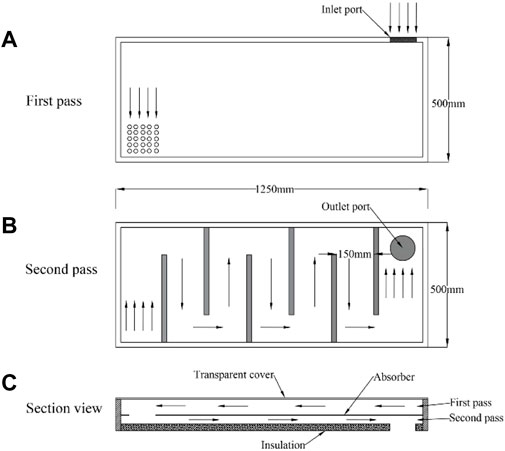
FIGURE 1. The direction of flow of air in the two-pass solar collector. (A) first pass, (B) second pass, (C) section view
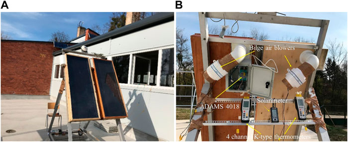
FIGURE 2. Solar collector setup. (A) Double-pass solar collector with fin (left) and without fin (right); (B) solar radiation measurement setup along with thermocouples.
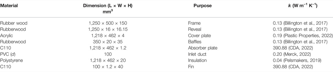
TABLE 1. Constructional details along with thermal conductivities of materials used for solar air heaters.
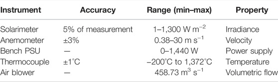
TABLE 2. The specification of instruments used for experimental purposes.
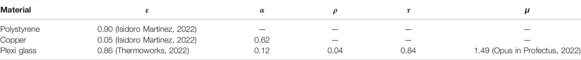
TABLE 3. Optical properties of constructional elements of solar air collectors.
Thermal Analysis of the Unit
The analysis is based on the quasi-static condition. The flat and finned plate collectors are analyzed separately employing some assumptions related to heat transfer coefficients and temperature (i.e., hfp = hff). The shear stress developed by the air stream and the velocity profile is examined critically by solving the Von Kármán momentum and Blasius equations for hydrodynamic boundary layers. The combination of ODE45 and PDPE solvers is used for the same purpose. The ground reflectivity (ρg) is assumed to be 0.20 (Duffie et al., 1994). It is assumed that the average temperature of the absorber plate and cover plate is equal to the average temperature of the air stream. Thus, the heat transfer coefficient due to radiation is estimated. The value of the extinction coefficient of glass (K) is taken to be 15 m−1. The schematic diagram is shown in Figure 3. MATLAB 2015b (MathWorks, New York, the United States) was used for a comprehensive analysis of both collectors.
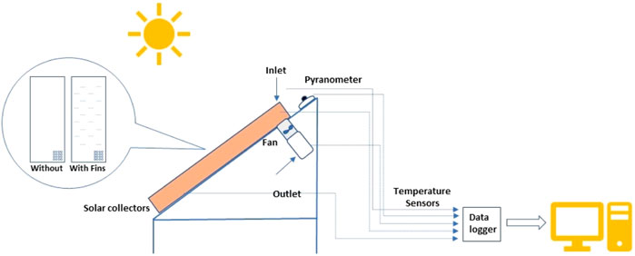
FIGURE 3. Schematic diagram of the experimental setup.
The following nonlinear ordinary equation for the laminar/turbulent boundary layer is given by Eq. 1
The initial value condition for the given problem is
At
The momentum integral equation for the hydrodynamic boundary is as follows
Apart from the estimation of the shear force factor, the friction factor (fg) for the finned plate collector (Eq. 3) and flat plate (Eq. 4) is estimated based on Reynold’s number. The following correlation is used for calculating the pressure drop
where,
Similarly, the value of the exponent can be given by
For a flat plate collector, it can be estimated through the given expression
The Dittus-Boelter equation is applicable if the clearance-to-spacing ratio is less than one for the finned collector (Duffie et al., 1994). Eq. 5 is adopted to estimate the heat transfer coefficient for the fin surface.
The following correlations are applied to estimate the heat transfer coefficient for a smooth surface (Thombre and Sukhatme, 1995)
The loss coefficient from the top cover is calculated according to the given empirical equation (Kays and Whitelaw, 1967)
where,
Valid for
The convective heat transfer at the top cover is calculated from the empirical correlation suggested by Mc Adams (McAdams, 1954; Klein, 1978)
Note: The additional details (error analysis, statistical data, and the formulation) are provided in the Supplementary Material.
Results and Discussion
The analyses of the two-pass flat plate collector and the flat plate with triangular fin were based on the flow behavior of the air stream and the heat transfer across the channel provided above and below the absorber plate due to forced convection. The Blasius and von Kármán momentum integral equations were used to comprehend the behavior of the incoming air.
Fluid Analysis of the Airstream
The numerical solution for the shear effect on the airstream along the absorber plate is illustrated in Figure 4. It was observed that the wall shear stress was significantly high at the trailing edge of the plate, except for the weak flow rate of air for a smooth absorber plate (FPC). It was seen that the behavior of the air stream in the vicinity of the solid boundary did not support the flow over the absorber surface at a mass flow rate of 8.10 g s−1, or the existence of a negative gradient velocity gradient (retardation effect) at y ∼ 0. Similar behavior was observed for a higher mass flow rate (12.10 g s−1) over the flat plate collector with triangular fins (FPTF). At a constant distance from the leading edge of the absorber plate, the shear stress (τ) posed by the flat plate collector (FPC) on the airstream dropped by 75.51% for the mass flow rate of 8.10 g s−1, when compared to the corresponding value obtained for FPTF. Likewise, the margin of the drop decreased by 23.74%, with the increase in the mass flow rate of 24.69%. But with the further increment of the mass flow rate by the same percentage (24.69%) for FPTF, the shear effect was seen to reverse its direction at the laminar sublayer. Relatively speaking, a remarkable leap of 134% was seen in the shear stress estimated for FPC at 12.10 g s−1. The maximum shear stress was seen at the lower mass flow over the triangular fins, whereas it was relatively low for the flat plate collector. The peak values of shear stress derived at 8.10 g s−1, 10.10 g s−1, and 12.10 g s−1 were 0.029 N m−2, 0.03 N m−2, and 0.0145 N m−2, respectively, for FPC. Similarly, the derived solutions were, correspondingly, 0.1459 N m−2, 0.07417 N m−2, and 0.06031 N m−2 at 8.10 g s−1, 10.10 g s−1, and 12.10 g s−1 in the case of FPTF. A small plateau build-up was noticed at 10.10 g s−1 for FPTF within 0.0247–0.029 m from the leading edge. The shear stress was almost constant for the given range of distance. With the increase in the mass flow rate, a positive displacement (towards the trailing edge of the absorber plate) of maxima was seen for FPTF. The net positive displacement varied from 0.0102 to 0.0145 m with the increase in the mass flow rate (24.69%–49.38%) over the triangular fins. Conversely, a negative displacement (towards the leading edge) was seen for FPC. At the same mass flow rate of 12.10 g s−1, the peak value of shear stress near the solid boundary was negatively displaced by 50% compared to the corresponding value derived for FPTF. Comparatively, there was a positive shift of 17.40% for FPC at 10.10, and at 8.10 g s−1 the positive displacement of peak shear stress was double the displacement of the corresponding value obtained for FPTF. This uneven displacement of shear stress value within the laminar sublayer zone may occur due to the influence of the thermal boundary layer on the viscous effect near the vicinity of the solid boundary, or because of the formation of a thermal gradient between the base plate and the triangular fin. The material dissimilarity could be for another reason, but the study primarily focused on the hydrodynamic boundary layer. The shear deformation rate will be maximum for a solar air collector with the triangular fin, and will decrease with an increase in the mass flow rate. In the case of a smooth plate, a higher mass flow rate will have a significant shear deformation rate. With the increase in the collector length, the effect of wall shear stress was subdued. A drastic drop in the values of
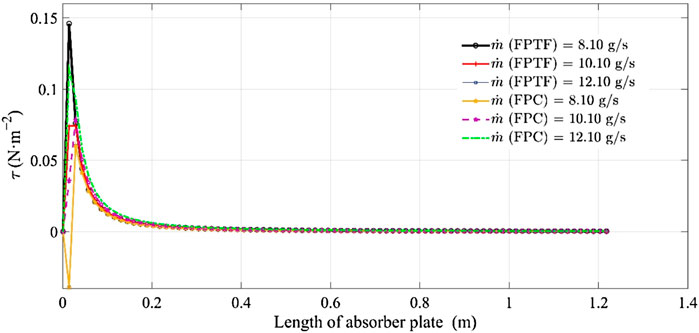
FIGURE 4. The change in the wall shear stress along the length of the absorber plate.
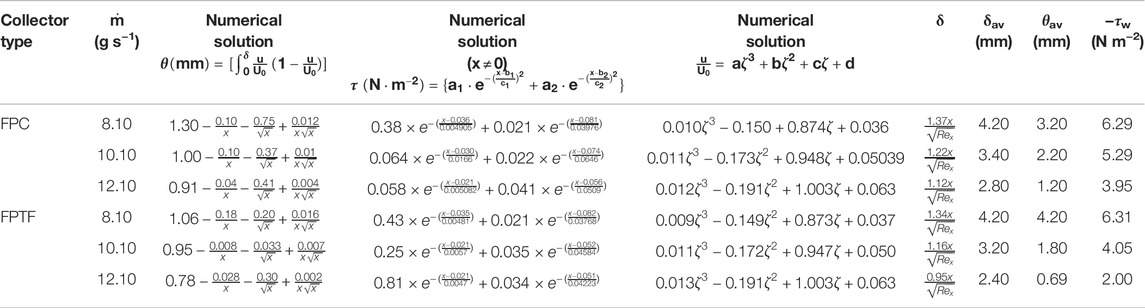
TABLE 4. The change in the velocity profile (u), momentum thickness (θ), and wall steer stress (τw) with the stretching factor (ζ) and length of a collector (x), respectively.
The variation in local velocity within the hydrodynamic layer was determined by solving the Blasius equation and the solution is shown in Figure 5. The effect of the stretching factor (η) on the local velocity of the airstream was seen to follow the linear model. The change in local velocity from the mainstream velocity at the same mass flow, as a result of the stretching factor, was found to be marginal for the different types of solar air collectors (FPC and FPTF). The regression model of order three provided a better fit than the numerical solution derived through the ordinary differential equation. RMSE was computed to vary from 0.001 to 0.01, whereas SSE was estimated to be in the domain of 10–03–10−02. The adjusted coefficient of regression (adj R2) for the given polynomial equation was 0.99. Since Reynold’s number was not highly affected by the momentum diffusivity of the air stream, it was noticed the numerical solution increased primarily with the channel height (y). At a constant distance from the leading edge of the absorber plate (FPTR), the local velocity near the solid boundary increased by 4.9% with the change in the mass flow rate from 8.10 to 10.10 g s−1. Similarly, the local velocity for FPC was augmented by 5% for the same change. So, in the case of FPC, a 2% increase in the local velocity was noticed within the hydrodynamic boundary layer. With the further rise in the mass flow rate (FPTF) to 12.10 g s−1, it was elevated by 3.34%, which is 31.83% lower than the change seen at 8.10–10.10 g s−1. It can be concluded that there is an optimum mass flow rate at which a rise can be observed and further change in the mass flow will not produce a promising outcome given the expense of auxiliary power. The relative drop in the local velocity with the further rise in the mass flow rate was 3.32%, which is marginally lower (∼1%) than the value obtained for FPTF. The change in the velocity gradient with channel height increased by 7.50% when the mass flow rate for FPC was elevated by 24.69%. With a further rise by the same mass flow rate %, the relative margin of change in the velocity gradient decreased by 44% for FPC. Similarly, in the case of FPTF, the relative margin dropped by 34.21% for the same range of mass flow rate. It could be concluded that the velocity gradient would be 22.22% higher for triangular fins than for the smooth plate given constant change in the mass flow rate of air.
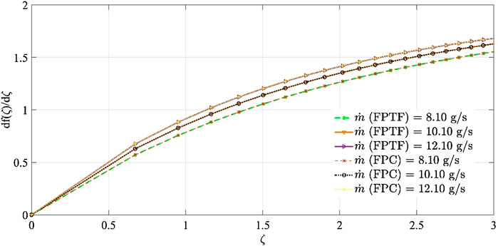
FIGURE 5. The change in the stretching function (f (ζ) with stretching factor ζ
The effect of boundary layer formation on the momentum of the airstream along the channel was determined by the change in the momentum thickness (θt) with the length of the absorber plate in Figure 6. At the leading edge of the absorber plate (FPC), θt was curtailed by 35.90% with the increase in the mass flow from 8.10 to 10.10 g s−1, and dropped further to 49.81% at 12.10 g s−1. In the case of FPTF, compared to FPC, the relative drop of θt was augmented by 66.57% for the same change in the mass flow rate (8.10–10.10 g s−1) of the incoming air. It also fell off to 68.66% at 12.10 g s−1, which is 37.84% higher than the recorded value for FPC at the same mass flow rate. This finding can also be validated with the average value of boundary layer thickness provided in Table 4. Both momentum (θt) and boundary layer (δ) thickness decreased with the increase in the mass flow rate of the air stream. The only difference was that the relative change in momentum defect was higher for a solar air collector with triangular fins. So, the flat surface, embedded with triangular fins, would see a drastic change in the momentum defect with an increase/decrease in the mass flow rate, although it would gradually change with the length of the absorber plate. The relationship between the momentum thickness and absorber plate was seen to vary according to the power-law distribution. A change in the sign of momentum thickness was observed for both solar air collectors (FPC and FPTF) at x = 0.0145 m. The reason for this deviation is the presence of surface irregularities that cause a recirculation zone within the air channel, and the upper layers trying to transfer the maximum momentum to the layer in the vicinity of the irregularity. The momentum transfer would be relatively higher for FPC at 8.10 g s−1. The momentum thickness recorded for FPC was 17.73% lower than the corresponding value of FPTF at the given location (0.0145 m) and mass flow of 8.10 g s−1.
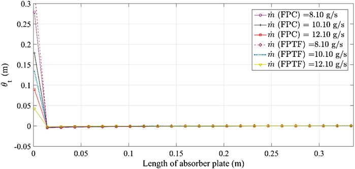
FIGURE 6. The variation of momentum thickness (θt) as a function of the length of absorber plate (x).
The statistical information and mathematical relationship between the numerical solutions are provided in Table 4. The average boundary layer thickness (δav) decreased by 19%–33.33% and 23.80%–42.85% when the mass flow rate was increased from 8.10 to 12.10 g s−1 for FPC and FPTF, respectively. That implies the local velocity along the solid boundary would be marginalized with the increase in the mass flow rate. Similarly, the average momentum thickness (θav) dropped correspondingly by 31.25%–62.5% and 57.14%–83.57% for FPC and FPTF. Relatively, θav for FPTF was 31.25% higher than that obtained for FPC at the lower mass flow rate (8.10 g s−1). Conversely, θav for FPTF dropped from 18.18 to 42.50% at the higher flow regime (10.10–12.10 g s−1). With the increase in the mass flow rate of air, average wall shear stress (τw) obtained for FPC and FPTF decreased by 15.89%–37.20% and 35.81%–68.30%, respectively. Relatively, at the lower mass flow rate, a 0.31% drop was observed for FPC, whereas it increased by 30.61%–97.50% when the flow rate stepped up from 10.10 to 12.10 g s−1. Hence, an inference can be drawn that the flat plate collector may be suitable for the lower mass flow rate, whereas this may not be the case for an absorber plate embedded with the triangular fins.
Heat Transfer Analysis
The variation in the solar energy fluxes within the experimental time frame (24-h) is shown in Figure 7. The effect of the month on the isolation was noticed in both beam and diffuse radiation. The extra-terrestrial radiation (Io) was estimated for the given days, and was seen to have its nadir point at 12.07 h. A similar trend was noticed while computing the beam radiation (Ib), and its minimum value was found to be 356.3 W m−2, which is 89.82% higher than the recorded value of Io at the same time.
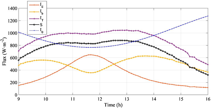
FIGURE 7. Variation in the flux incident on the solar air collectors.
At the same time, diffuse radiation (Id) obtained its maximum value, which is 81.61% higher than the corresponding value obtained for beam radiation. However, two local maxima were seen in the beam radiation at 10 and 14.07 h, respectively. A 12% leap was noticed in the local maxima Ib in the afternoon. It is not that Io was influential throughout the time cycle. The predominant change in Io on Ib was seen between 11 and 12 h. The declining trend in Io was observed from 9 to 11 h. The estimated change in slope of curve for the given period was −89.50°, while it was 89.48° for beam radiation. A near-orthogonality was perceived between the gradients of these radiations at the onset of experimentation. Both radiations (Io and Ib) would have the same magnitude at 10 and 13.42 h. Similarly, for diffuse radiation (Id), the magnitude would be the same at nearly 11 and 13 h. The effect of curvature
The change over time in the stagnant temperature (Tst) of the top (Ist) and lower (IInd) surfaces of absorber plates of both FPC and FPTF is shown in Figures 8A,B. The maximum Tst for the top surface of the absorber plate (FPC) was found to be 375.80 K at 12:50, whereas it dropped by 4% at the same time for the channel underneath the absorber plate of FPC at 8.10 g s−1. This can also be seen in Figure 8A. If there is a useful gain of heat energy by air stream (qu), the given two-pass design of the absorber plate would not exceed 356.40 K, which is 5.16% and 1.19% lower than the obtained value of the plate for the Ist pass and IInd pass, respectively, at 8.10 g s−1. The distribution pattern for stagnant temperature would differ by magnitude. The characteristic change in the stagnant temperature distribution at Ist and IInd passes was not noticed. Theoretically, the stagnant temperature is the maximum temperature limit that an absorber plate can have if there is no useful gain of heat energy (qu = 0), but it was observed at the sporadic interval where the local stagnant temperature dropped marginally by a small fraction for the second pass (IInd). At 11:50 p.m., the local stagnant temperature fell by 0.39%. Similarly, Tst dropped by 0.35%–3.26% for the period of 15.10–16 h. The local stagnant temperature for the Ist pass was seen to have decreased by 2.78% at 15:45. The reason for this peculiarity was the involvement of ambient air effect on the overall loss coefficient (Ul), therefore some fluctuation in temperature was noticed at that instant of time.
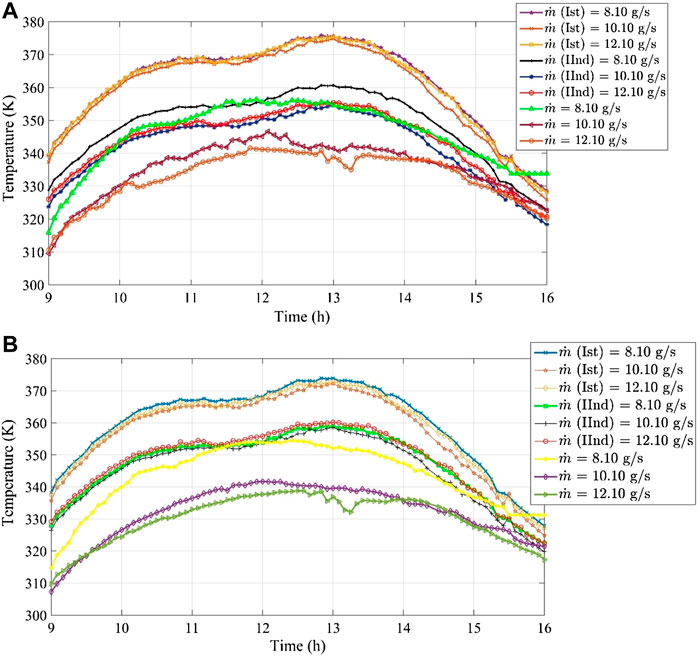
FIGURE 8. The change in stagnant temperature (Tst) of absorber plate with time. (A) Flat plate collector; (B) flat plate collector with fins.
With the increase in the mass flow to 10.10 g s−1, Tst dropped marginally by 0.27% along the first passage (Ist), whereas the lowered margin increased to 1.66% when Tst at 10.10 g s−1 was compared with its corresponding value at 8.10 g s−1 for the IInd pass. So, it was noticed the mass flow rate markedly influenced the temperature distribution of the back side of the absorber plate (FPC). The experimentally measured temperature of the absorber for the normal condition was also observed to have decreased by 2.74% at 10.10 g s−1. A small temporal shift in the temperature distribution pattern was also seen with the increase in the mass flow rate by 24.69%. The maximum temperature of the absorber plate was observed at 12:05 p.m. for 10.10 g s−1. The stagnant temperature for the back side of the absorber plate (FPC) at 10.10 g s−1 was seen to have dwindled by 0.45%–1.30% for the period of 15.25–16 h. However, Tst for the front surface of the absorber plate was at an all-time high over the experimentally measured temperature of the absorber plate. The relative drop in Tst of the front surface (Ist) of absorber plate (FPC) at 12.10 g s−1 was seen to be 0.07%, compared to Tst (FPC) at 8.10 g s−1. However, it increased to 1.44% for the back side of the absorber for FPC. In totality, ΔTst at 8.10 g s−1 is higher than the corresponding value obtained at 10.10 g s−1 for FPC. A mammoth change at different mass flow rates in ΔTst was computed between 11: 00 and 14: 00.
In the case of FPTF, Tst (373.90 K) at 8 g s−1was reduced by 0.50% for the Ist pass when compared with the corresponding value of FPC. The time-related shift was not perceived. As compared to Tst for the Ist pass, it was reduced by 3.98% for the back surface of the absorber plate, which is negligibly lower than that derived in the case of FPC. The maximum temperature of the absorber plate at normal condition (qu
The change in total heat gain (qu) of the air stream and the overall loss coefficients (Ul) for the first and second channels of FPC and FPTF are illustrated in Figures 9A,B. While operating FPC, the standard deviations in the heat gain rate (qu) at 8.10 g s−1, 10.10 g s−1, and 12. 10 g s−1 were 83.16, 91.26, and 98.25 W, respectively, which are relatively lower than those estimated for FPTF. The estimated standard deviation in qu for FPTF increased by 8.69%–13.26%. The higher mass flow rate in FPTF influences the density function of qu and it was seen that kurtosis (Kr) (the leptokurtic distribution) for qu decreased by 12.16%–13.22% with the increase in the mass flow rate for FPTF, whereas the distribution pattern was negatively skewed for the tested mass flow rate. However, the skewness encountered a rise by the margin of 10.21%–12.33%. Hence the overall probability of seeing a large variation around the average value of qu for FPTF will be great at the higher flow regime. However, the Kr of qu distribution derived for FPC changed marginally from 2.24 to 3.56%. Both the collectors provide a similar kind of distribution (leptokurtic).
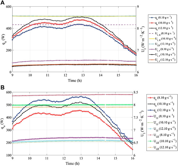
FIGURE 9. The change in the heat gain (qu)/overall loss coefficient (Ul) with time. (A) Flat plate collector (FPC); (B) flat plate collector with triangular fins (FPTF).
The skewness of qu for FPC was also not much influenced by the increase in the mass flow rate and the drop was in the range of 2.33%–2.94%. Relatively speaking, the change in the flow regime will not greatly affect the likelihood of getting a reasonable heat gain rate for FPC. The change in the overall loss coefficient (Ul, I) for the flow between the cover and absorber plate (FPC) was uniform throughout the experimental process. The estimated value of the standard deviation (SD) in Ul, I decreased with the increase in the mass flow rate. The drop noticed in the SD varied from 67.33 to 76.55%. The maximum value of Ul, I was estimated to be in the range of 5.81–6.10 W m−2 K−1. The upper bound value of Ul, I was observed at 8.10 g s−1. The Ul, I data set is negatively skewed, but the skewness increased with the increase in the mass flow rate. Similarly, Kr for Ul, I was also elevated from 2.65 to 4.74% with the rise in the mass flow rate. The likelihood of constantly higher losses would be enhanced with the increase in the mass flow rate, despite the maximum loss coefficient (Ul, I) being relatively low for a higher flow regime for FPC. The maximum overall loss coefficient Ul, II for the flow between the absorber plate and insulator (IInd Pass) increased by 4.77%–4.90% as the flow rate below the absorber plate (IInd) fortified. The variation in the SD of Ul, II data reduced by 0.52%–19.29% with the rise in the mass flow rate of the air stream. The overall loss coefficient increased with an increase in the number of passes. At the constant mass flow rates, Ul increased from 33.86 to 47.18% for the FPC design. The distribution of Ul, II was positively skewed and the skewness of the data set increased from 0.35 to 7.13%. The kurtosis for Ul, II was also elevated by 3%–4.72%.
In the case of FPTF, the loss coefficient Ul, II relative to Ul, I was elevated by 20%–25%. However, Ul, II decreased when increasing the mass flow rate from 8.10 to 12.10 g s−1. At the same mass flow rate, Kr derived for FPTF was 29.39% higher than the corresponding value obtained for FPC. Unlike FPC, Kr for Ul, I dataset decreased by 6.23%–25.83% with the rise in the mass flow rate. That implies variability (outliers) in the data behavior of Ul, I would be relatively low with the triangular fins at a higher flow rate. The distribution of Ul, I for FPTF is negatively skewed, but is approached to attain symmetrical behavior around the mean value with an increase in the mass flow rate over the triangular fins. That means a higher flow rate may provide a uniform rate of heat loss across the first channel (Ist). The average value of Ul, II for the second channel (IInd) decreased by 4.76%–5.95% with an increasing mass flow rate. According to statistical analysis, the negative skewness in Ul, II increased by 47.91%–147.29%, which shows Ul, II will rise with the increase in the mass flow rate between the absorber plate and the insulator. The Kurtosis for Ul, II was increased by 32.61%–83.81% as the mass flow rate increased from 8.10 to 12.10 g s−1.
The change in the instantaneous efficiency ηI % with time (h) for both FPC and FPTF is shown in Figure 10. It can be seen that for both the collectors the increase in the mass flow rate increases ηI by magnitude. The change in shape factor of distributions of ηI was not seen. The relative variabilities in the distribution behavior of ηI for FPTF dropped by 7.82%, 25.02%, and 21.75%, as compared to ηI obtained for FPC, at 8.10 g s−1, 10.10 g s−1, and 12.10 g s−1, respectively. Relatively, the average collector efficiency (ηI) of FPTF was augmented by 5.52%–12.80% at the same mass flow rate due to the incorporation of triangular fins on the top surface of the absorber plate. However, when the maximum value of ηI for FPTF was compared with FPC, it had dropped relatively by 6.25%. The reason for this peculiarity is an increase in the skewness of ηI for FPTF data for FPTF of 4.90% which provided this deviation between the maximum and mean values of ηI for FPTF.
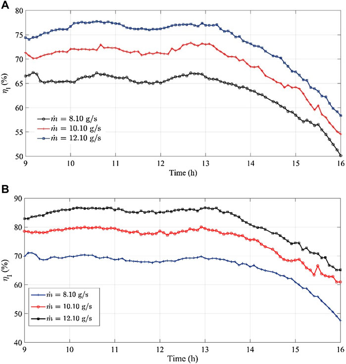
FIGURE 10. The change in the collector efficiency (ηI) with time. (A) Flat plate collector; (B) flat plate collector with fins.
The other response variables, such as efficiency, heat removal, and collector efficiency factors, also rely on the explanatory variable Ul, and equivalent he and radiative heat transfer coefficients hr. The time-related variations in these factors and he and hr are shown in Figures 11A,B.
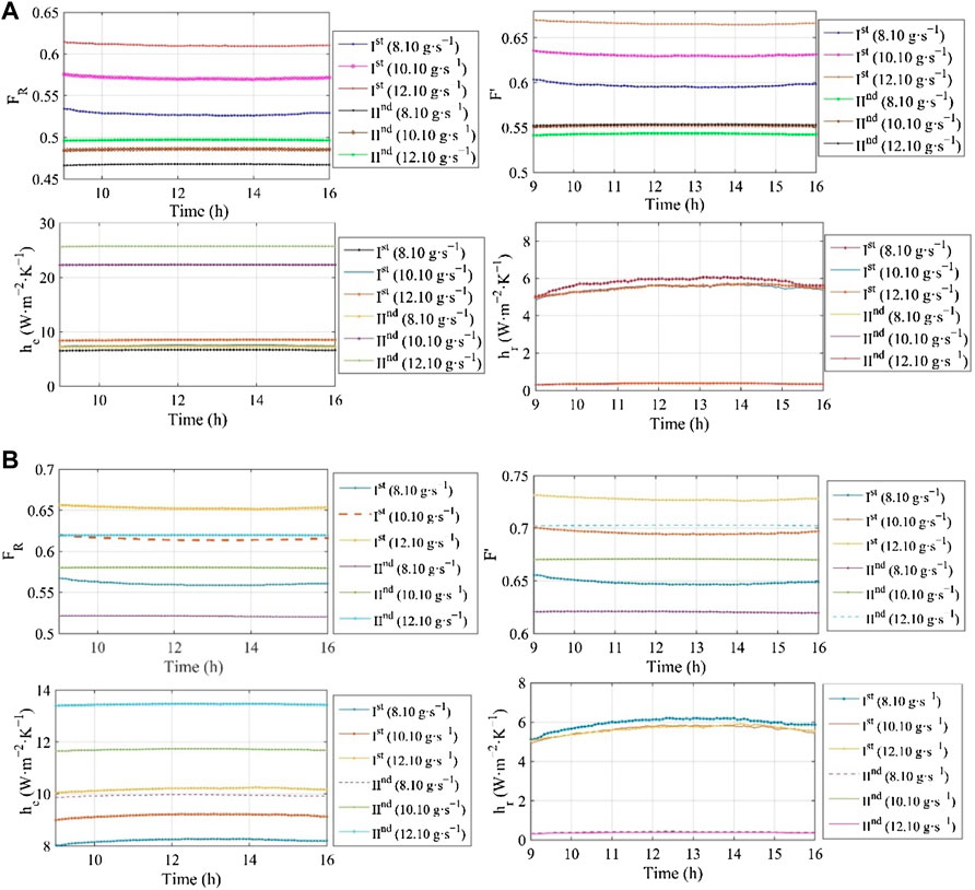
FIGURE 11. The change in collector (F′) and heat removal (FR) factors along with equivalent (he) and radiative (hr) heat transfer coefficient. (A) Flat plate collector; (B) flat plate collector with fins.
The heat removal factor (FR) for the first channel (Ist) was compared for both FPC and FPTF. It was elevated by 6.63% at the constant flow rate of 8.10 g s−1 for FPTF when compared with the corresponding value for FPC. Similarly, it also increased from 6.63 to 8.92% when the mass flow rate was elevated from 8.10 to 10.10 g s−1, but with the further increase in mass flow rate, it dropped by 22.30% for FPTF. The reason for this change anomaly is the overall heat loss coefficient Ul, I, which is discussed above in detail (Figure 9). However, such peculiarity was not seen in the flow behind the absorber plate. In the case of FPTF, the value of FR for the second channel monotonically increased from 11.45 to 24.71% with the rise in the air stream flow rate. A similar sort of variation was also observed for the collector efficiency factor (F′) of FPTF, which initially increased from 9.10% to 11.49% for the mass flow rate of 8.10–12.10 g s−1. But with further change in the mass flow rate, it dropped by 19.58%. For the second channel (IInd), the relative increase in F′ for FPTF was 14.31%–27% with the change in the mass flow rate from 8.10 to 12.10 g s−1. Comparatively, the radiative heat transfer coefficient hr (Ist) for FPTF was reduced by 3.07%–13.64% as the mass flow rate increased from 8.10 to 10.10 g s−1. With a further increase in mass flow rate to 12.10 g s−1, hr (Ist) was elevated by 2.34%. Conversely, as compared to hr (IInd) for FPC, the radiative heat coefficient hr (IInd) behind the absorber plate for FPTF soared up from 4.38% to 4.91% for the mass flow interval of 8.10–10.10 g s−1. However, as the mass flow rate increased to 12.10 g s−1, it dropped relatively by 12.83% for FPTF. Likewise, the equivalent heat transfer coefficient [he (Ist)] for FPTF was 12.45% higher than the corresponding value of he (Ist) for FPC at 8.10 g s−1. With the increase in the mass flow rate, the value of he (Ist) for FPTF was reduced by 58.61%–60.40%. However, it sharply increased for the IInd pass behind the absorber plate. The computed value of he (IInd) was markedly enhanced from 37.29% (8.10 g s−1) to 86.60% (12.10 g s−1) for FPTF when it was equated with a corresponding value of he (IInd) for FPC. So, the major convective losses at IInd are relatively high for FPTF design at the lower mass flow rate, whereas it is the other way round for the flow between the absorber plate and glazing (Ist). The parametric details for both collectors are in Tables 5, 6. The calculated heat transfer coefficient for FPC between the air stream and cover plate (hfp) varies from 4.20 to 5.70 W m−2 K−1, which is 25%–27% relatively lower than the corresponding value of hfp derived at the same mass flow rate for FPTF. An increase in hfp [by 17.14%–35.71% (FPC) and 19.23%–38.16% (FPTF)] was noticed as the mass flow rate changed from 8.10 to 12.10 g s−1. Reynold’s number (Re) for FPTF dropped by 5%–6.69%. The reduction would be higher at the low mass flow rate. Conversely, the Nusselt number (Nu) for a solar air collector with triangular fins (FPTF) was 18.93%–20.74% higher than that of FPC. It was elevated for both FPC and FPTF with the increase in the mass flow rate. The pressure drop (ΔP) was strikingly high for FPTF when its values were equated with the corresponding values for FPC. It varied from 7.39 N m−2 to 17.87 N m−2 for FPTF, whereas it was in the range of 2.59 × 10–02 –0.38 N m−2 for FPC. The presence of a baffle in the FPTF design enhanced the pressure drop along the second channel tremendously. However, it also impacted the FPC design, although the relative magnitude was quite low (Tables 5, 6). The top loss coefficient (Ut) for FPTF plummeted by 0.16%–1.7%, compared to the corresponding value of Ut for FPC.
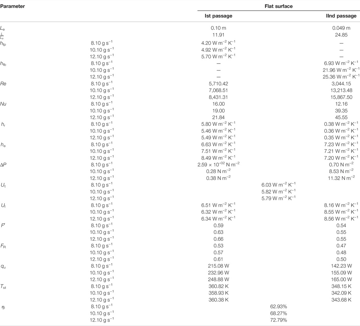
TABLE 5. Parametric information of solar air collectors (flat plate collector with two-pass).
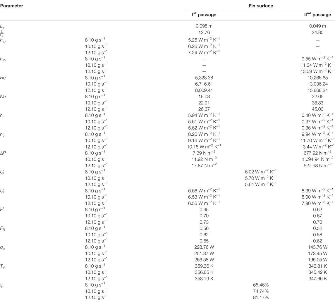
TABLE 6. Parametric information of solar air collectors (finned plate collector with two-pass).
Energy Diagram
The energy distribution for FPC and FPTF is illustrated in Figure 12. The net loss across the second channel was 13%–15.94% of the total solar energy provided to the FPC, which is 10.28% lower than the loss encountered in FPTF along the same channel (IInd) at a mass flow rate of 8.10 g s−1; however it increased by 11.46%–22.61% with an increase in the mass flow rate for FPC. The net energy gain quotas of total solar energy provided to the cover plate for the mass flow rate of 8.10 g s−1, 10.10 g s−1, and 12.10 g s−1 were, respectively, 24.63%, 27.53%, and 28.98% at the outlet of FPC. The net energy gain share at the outlet of FPTF outplayed the FPC design by a margin of 5.56%–20%. At the inlet, as compared to FPC, the share of energy losses from the cover plate slumped by 8.33%–10.53% of total solar energy provided to the collector for FPTF. Conversely, as compared to FPC, the relative increase in the heat gain quota of air stream through the top surface of the absorber plate of FPTF was estimated to be 6.45%–7.66% with the increase in the mass flow rate from 8.10 g s−1 to 12.10 g s−1. The lower bound share of heat gain for the Ist channel was 16% higher than the lower bound value (5.56%) obtained for the second channel of FPTF, but it plunged by a huge margin of 61.70% when the upper bound value of heat gain from the IInd pass was compared. It can be concluded that the optimization of mass flow rate may improve the performance of FPTF.
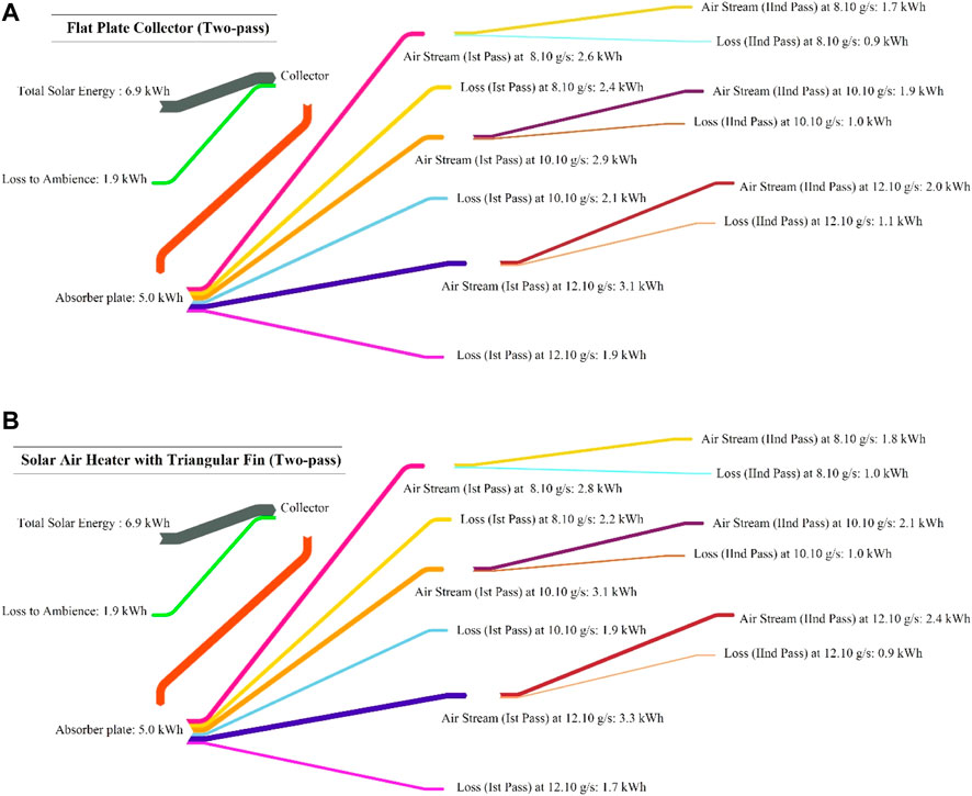
FIGURE 12. Energy diagram for the solar air collectors. (A) Flat plate collector; (B) flat plate collector with fins.
Conclusion
The gray box modeling approach was adopted to examine the hydrodynamic behavior of air along the first pass for two-pass solar air collectors with and without fins. For heat energy analysis, a quasi-steady state scheme was assumed to solve the energy equations for flow above and below the absorber plate. Some relevant findings related to rheological and heat analyses are summarized below:
1. From the hydrodynamic point of view, the peak value of τ was reduced by 3.4%–50% with the increase in mass flow rate for FPC. Similarly, the value of τ also dropped for the FPTF design by 50%–57.14%. The relative effect of mass flow rate on τ was significantly high for the FPTF design. It can be stated that the increase in the mass flow rate over the top surface of the absorber plate of FPTF is reflects the comparative desire to deal with the viscous effect of air near the solid boundary. With the increase in the mass flow rate of air, the average wall shear stress (τw) calculated for FPC and FPTF decreased by 15.89%–37.20% and 35.81–68.30%, respectively. It was noticed from shear stress analysis that the flat plate collector may be suitable for the lower mass flow rate, which may not be the case for an absorber plate embedded with the triangular fins.
2. For the same mass flow rate over the surface of the absorber plates, the velocity gradient computed for the FPTF design is 22.22% higher than that obtained for FPC. At a constant distance from the leading edge of the absorber plate (FPTR), the local velocity near the solid boundary increased by 4.9% with the change in the mass flow rate from 8.10 to 10.10 g s−1. Similarly, the local velocity for FPC was augmented by 5% for the same change.
3. The momentum thickness (θt) at the leading edge of the absorber plate (FPC) was reduced by 35.90% when the flow rate increased from 8.10 to 10.10 g s−1. An additional drop of 49.81% was recorded at 12.10 g s−1. By comparison, θt decreased by 66.57% for the same change in the mass flow rate (8.10–10.10 g s−1) of the incoming air in the case of FPTF.
4. From mathematical observation of the equation, it was seen that with the change in the angle of tilt in the open interval of 30°–90°, the diffuse radiation would have the least share in the total global radiation, but the global radiation should be higher than 0.26 Io and 0.56 Io.
5. The maximum Tst = 375.80 K for the top surface of the absorber plate (FPC) was recorded at 12:50 p.m. However, it was reduced by 4% at the same time for the IInd pass of FPC at 8.10 g s−1. The stagnant temperature for FPTF, Tst was reduced by 0.50% for the top surface of the absorber plate at 8 g s−1 when compared with the corresponding value of FPC.
6. The increase in the mass flow rate of the airstream influenced the character of the density function of qu for FPTF. It was seen that kurtosis (Kr) for qu decreased by 12.16%–13.22% with the increase in the mass flow rate. The leptokurtic distribution would predict the total heat gain to the air stream in both FPC and FPTF. The likelihood of large variation in qu with the increase in the mass flow rate is high for FPTF. However, by comparison, the change in the mass flow rate will not much affect the likelihood of a reasonable heat gain rate for FPC.
7. At the same mass flow rate, the variability in the distribution behavior of ηI for FPTF will decrease by 7.82%–21.75% compared to the corresponding value of ηI for FPC. Compared to FPC, the calculated average collector efficiency (ηI) for FPTF increased by 5.52%–12.80% at the same mass flow rate.
8. The net heat gain shares of total solar energy received by FPC and FPTF at a mass flow rate of 8.10 g s−1, 10.10 g s−1, and 12.10 g s−1 were found to be 24%, 27.53%, 28.98%, 30%, and 34.78%, respectively.
It can be concluded from this analysis that the flat plate collector with triangular fins is relatively susceptible at a higher mass flow rate, while the flat plate collector has flexibility regarding the mass flow rate. The pressure drop will be enormous if baffles are provided with the FPTF design.
Data Availability Statement
The original contributions presented in the study are included in the article; further inquiries can be directed to the corresponding author.
Author Contributions
AD: conceptualization, methodology, software, validation, formal analysis, investigation, resources, data curation, software, writing—original draft preparation, writing—review and editing, and visualization.
Conflict of Interest
The authors declare that the research was conducted in the absence of any commercial or financial relationships that could be construed as a potential conflict of interest.
Publisher’s Note
All claims expressed in this article are solely those of the authors and do not necessarily represent those of their affiliated organizations, or those of the publisher, the editors and the reviewers. Any product that may be evaluated in this article, or claim that may be made by its manufacturer, is not guaranteed or endorsed by the publisher.
Supplementary Material
The Supplementary Material for this article can be found online at: https://www.frontiersin.org/articles/10.3389/fenrg.2022.949226/full#supplementary-material
References
Ammar, M., Mokni, A., Mhiri, H., and Bournot, P. (2020). Numerical Analysis of Solar Air Collector provided with Rows of Rectangular Fins. Energy Rep. 6, 3412–3424. doi:10.1016/j.egyr.2020.11.252
Badiei, Z., Eslami, M., and Jafarpur, K. (2020). Performance Improvements in Solar Flat Plate Collectors by Integrating with Phase Change Materials and Fins: A CFD Modeling. Energy 192, 116719. doi:10.1016/j.energy.2019.116719
Billington, M., Barnshaw, S., Bright, K., and Crooks, A. (2017). The Building Regulations and Approved Documents. 2.1–2.32. doi:10.1002/9781119070818
Cda, (2022). CDA Copper No. C 11000. Available online http://www.husseycopper.com/wp-content/uploads/2013/11/c11000_new.pdf (accessed on February 23rd, 2022).
Chaichan, M. T., Abaas, K. I., and Kazem, H. A. (2016). Design and Assessment of Solar Concentrator Distillating System Using Phase Change Materials (PCM) Suitable for Desertic Weathers. Desalination Water Treat. 57 (32), 14897–14907. doi:10.1080/19443994.2015.1069221
Das, B., Mondol, J. D., Negi, S., Smyth, M., and Pugsley, A. (2021). Experimental Performance Analysis of a Novel Sand Coated and Sand Filled Polycarbonate Sheet Based Solar Air Collector. Renew. Energy 164, 990–1004. doi:10.1016/j.renene.2020.10.054
Dhaundiyal, A., and Atsu, D. (2022). The Effect of Thermo-Fluid Properties of Air on the Solar Collector System. Alexandria Eng. J. 61 (4), 2825–2839. doi:10.1016/j.aej.2021.08.015
Dhaundiyal, A., Gebremichael, G. H., and Atsu, D. (2021). Comprehensive Analysis of a Solar Dryer with a Natural Draught. Energy Sources, Part A: Recovery, Utilization and Environmental Effects. doi:10.1080/15567036.2021.1951899
Dissa, A. O., Ouoba, S., Bathiebo, D., and Koulidiati, J. (2016). A Study of a Solar Air Collector with a Mixed "porous" and "Non-porous" Composite Absorber. Sol. Energy 129, 156–174. doi:10.1016/j.solener.2016.01.048
Duffie, J. A., Beckman, W. A., and Worek, W. M. (1994). Solar Engineering of Thermal Processes, 2nd Ed. J. Sol. Energy Eng. 116 (1), 67–68. doi:10.1115/1.29300682nd ed
Dutta, P., Dutta, P. P., Kalita, P., Goswami, P., and Choudhury, P. K. (2021). Energy Analysis of a Mixed-Mode Corrugated Aluminium Alloy (AlMn1Cu) Plate Solar Air Heater. Mater. Today Proc. 47, 3352–3357. doi:10.1016/j.matpr.2021.07.156
El-Sebaii, A. A., and Al-Snani, H. (2010). Effect of Selective Coating on Thermal Performance of Flat Plate Solar Air Heaters. Energy 35 (4), 1820–1828. doi:10.1016/j.energy.2009.12.037
Fan, M., You, S., Gao, X., Zhang, H., Li, B., Zheng, W., et al. (2019). A Comparative Study on the Performance of Liquid Flat-Plate Solar Collector with a New V-Corrugated Absorber. Energy Convers. Manag. 184, 235–248. doi:10.1016/j.enconman.2019.01.044
Farajzadeh, E., Movahed, S., and Hosseini, R. (2018). Experimental and Numerical Investigations on the Effect of Al2O3/TiO2H2O Nanofluids on Thermal Efficiency of the Flat Plate Solar Collector. Renew. Energy 118, 122–130. doi:10.1016/j.renene.2017.10.102
Gao, M., Wang, D., Liu, Y., Wang, Y., and Zhou, Y. (2020). A Study on Thermal Performance of a Novel Glazed Transpired Solar Collector with Perforating Corrugated Plate. J. Clean. Prod. 257, 120443. doi:10.1016/j.jclepro.2020.120443
Hans, V. S., Saini, R. P., and Saini, J. S. (2010). Heat Transfer and Friction Factor Correlations for a Solar Air Heater Duct Roughened Artificially with Multiple V-Ribs. Sol. Energy 84 (6), 898–911. doi:10.1016/j.solener.2010.02.004
Isidoro Martinez (2022). Properties of Solids. Available at: http://imartinez.etsiae.upm.es/∼isidoro/dat1/eSol.pdf (Accessed 2003, 2022).
Karim, M., and Hawlader, M. (2006). Performance Investigation of Flat Plate, V-Corrugated and Finned Air Collectors. Energy 31 (4), 452–470. doi:10.1016/j.energy.2005.03.007
Kays, W. M., and Whitelaw, J. H. (1967). Convective Heat and Mass Transfer. J. Appl. Mech. 34 (1), 254. doi:10.1115/1.3607663
Klein, S. A. (1978). Calculation of Flat-Plate Collector Utilizability. Sol. Energy 21 (5), 393–402. doi:10.1016/0038-092x(78)90171-8
Koca, A., Oztop, H. F., Koyun, T., and Varol, Y. (2008). Energy and Exergy Analysis of a Latent Heat Storage System with Phase Change Material for a Solar Collector. Renew. Energy 33 (4), 567–574. doi:10.1016/j.renene.2007.03.012
Krishnananth, S. S., and Kalidasa Murugavel, K. (2013). Experimental Study on Double Pass Solar Air Heater with Thermal Energy Storage. J. King Saud Univ. - Eng. Sci. 25 (2), 135–140. doi:10.1016/j.jksues.2012.05.004
Kumar, R., Sethi, M., Chauhan, R., and Kumar, A. (2017). Experimental Study of Enhancement of Heat Transfer and Pressure Drop in a Solar Air Channel with Discretized Broken V-Pattern Baffle. Renew. Energy 101, 856–872. doi:10.1016/j.renene.2016.09.033
Lin, W., Ren, H., and Ma, Z. (2020). Mathematical Modelling and Experimental Investigation of Solar Air Collectors with Corrugated Absorbers. Renew. Energy 145, 164–179. doi:10.1016/j.renene.2019.05.129
Merck (2022). Polyvinyl Chloride Density Strength Melting Point Thermal Conductivity. Available at: https://material-properties.org/polyvinyl-chloride-density-strength-melting-point-thermal-conductivity/(accessed on February 23rd, 2022).
Mohammadi, K., and Sabzpooshani, M. (2013). Comprehensive Performance Evaluation and Parametric Studies of Single Pass Solar Air Heater with Fins and Baffles Attached over the Absorber Plate. Energy 57, 741–750. doi:10.1016/j.energy.2013.05.016
Müller, S., Giovannetti, F., Reineke-Koch, R., Kastner, O., and Hafner, B. (2019). Simulation Study on the Efficiency of Thermochromic Absorber Coatings for Solar Thermal Flat-Plate Collectors. Sol. Energy 188, 865–874. doi:10.1016/j.solener.2019.06.064
Naphon, P., and Kornkumjayrit, K. (2008). Numerical Analysis on the Fluid Flow and Heat Transfer in the Channel with V-Shaped Wavy Lower Plate. Int. Commun. Heat Mass Transf. 35 (7), 839–843. doi:10.1016/j.icheatmasstransfer.2008.03.010
Natarajan, E., and Sathish, R. (2009). Role of Nanofluids in Solar Water Heater. Int. J. Adv. Manuf. Technol. 45 (7), 1–5. doi:10.1007/s00170-008-1876-8
Nowzari, R., Aldabbagh, L. B. Y., and Egelioglu, F. (2014). Single and Double Pass Solar Air Heaters with Partially Perforated Cover and Packed Mesh. Energy 73, 694–702. doi:10.1016/j.energy.2014.06.069
Opus in Profectus (2022). The Physics Hypertextbook. Available at: https://physics.info/refraction/(Accessed 2003, 2022).
Pelsmakers, S. (2019). The Environmental Design Pocketbook, the Environ-Mental Design Pocketbook. doi:10.4324/9780429347573
Plastic Properties (2022). Plastic Properties. Available online https://www.emcoplastics.com/assets/pdf/plexiglas/Plexiglas%20General%20Infor-mation%20and%20Properties.pdf (accessed on February 23rd, 2022).
Sharma, S. K., and Kalamkar, V. R. (2017). Experimental and Numerical Investigation of Forced Convective Heat Transfer in Solar Air Heater with Thin Ribs. Sol. Energy 147, 277–291. doi:10.1016/j.solener.2017.03.042
Soum-Glaude, A., Le Gal, A., Bichotte, M., Escape, C., and Dubost, L. (2017). Optical Characterization of TiAlN X /TiAlN Y /Al 2 O 3 Tandem Solar Selective Absorber Coatings. Sol. Energy Mater. Sol. Cells 170, 254–262. doi:10.1016/j.solmat.2017.06.007
Thermoworks (2022). Infrared Emissivity Table. Available at: https://www.thermoworks.com/emissivity-table/(Accessed 2003, 2022).
Thombre, S. B., and Sukhatme, S. P. (1995). Turbulent Flow Heat Transfer and Friction Factor Characteristics of Shrouded Fin Arrays with Uninterrupted Fins. Exp. Therm. Fluid Sci. 10 (3), 388–396. doi:10.1016/0894-1777(94)00059-h
Ural, T. (2019). Experimental Performance Assessment of a New Flat-Plate Solar Air Collector Having Textile Fabric as Absorber Using Energy and Exergy Analyses. Energy 188, 116116. doi:10.1016/j.energy.2019.116116
Nomenclature
a, b, c, d coefficients of the linear model
f the function of the stretching factor
fg fanning friction factor for airstream
FPC flat plate collector
FPTF flat plate with triangular fins
FR and F′ heat removal and collector efficiency factors, respectively
hfp, and hff heat transfer coefficient between the air stream and cover plate, and between air stream and fins, respectively, W m−2 K−1
hr and he radiative and equivalent heat transfer coefficient, W m−2 K−1
hw convective heat transfer coefficient for ambient air, W m−2 K−1
Ib and Id beam and diffused radiation, respectively, W m−2
Io extraterrestrial radiation, W m−2
IT and S flux absorbed by the cover plate and absorber plate, respectively, W m−2
k thermal conductivity of materials, W m−1 K−1
L, Lf airstream passage spacing and the length of the fin, respectively, m
Nu, Pr re nusselt, prandtl and reynold numbers, respectively
qu the useful heat gain by the air stream, W
Ta and Tst ambient and stagnant temperature, respectively, K
Tpm mean temperature of the absorber plate, K
u airstream velocity inside the boundary, m s−1
U0 mainstream velocity, m s−1
Ut and Ul top loss and the overall loss coefficient, respectively, W m−2 K−1
x a particular position from the trailing edge, m
y traverse length from the absorber plate, m
α absorptivity of material used for construction
β the tilt angle of the solar air collector
δ hydrodynamic boundary layer, m
ε, ρ, τ, µ emissivity, reflectivity, transmissivity, and refractive index, respectively
εp,εc the emissivity of cover and absorber plates, respectively
ζ stretching factor
ηI instantaneous efficiency of the collector
θt momentum thickness, m
ν kinematic viscosity of the moving air stream, m2 s−1
τw shear stress on the absorber plate, N m−2
Keywords: heat transfer, solar collector, shear effect, solar radiation, boundary layer
Citation: Dhaundiyal A (2022) Rheological Behavior of Air in the Two-Pass Solar Collector. Front. Energy Res. 10:949226. doi: 10.3389/fenrg.2022.949226
Received: 20 May 2022; Accepted: 21 June 2022;
Published: 16 August 2022.
Edited by:
Haoran Li, Northeast Electric Power University, ChinaReviewed by:
Basma Souayeh, King Faisal University, Saudi ArabiaDaniel Tudor Cotfas, Transilvania University of Brașov, Romania
Copyright © 2022 Dhaundiyal. This is an open-access article distributed under the terms of the Creative Commons Attribution License (CC BY). The use, distribution or reproduction in other forums is permitted, provided the original author(s) and the copyright owner(s) are credited and that the original publication in this journal is cited, in accordance with accepted academic practice. No use, distribution or reproduction is permitted which does not comply with these terms.
*Correspondence: Alok Dhaundiyal, RGhhdW5kaXlhbC5BbG9rQGhvdG1haWwuY29t