
95% of researchers rate our articles as excellent or good
Learn more about the work of our research integrity team to safeguard the quality of each article we publish.
Find out more
ORIGINAL RESEARCH article
Front. Energy Res. , 23 August 2022
Sec. Process and Energy Systems Engineering
Volume 10 - 2022 | https://doi.org/10.3389/fenrg.2022.947391
This article is part of the Research Topic Materials, Process, and Applications in Energy Storage Systems View all 5 articles
 Mohammadreza Ebrahimnataj Tiji1
 Hayder I. Mohammed2
 Raed Khalid Ibrahem3Anmar Dulaimi4
 Jasim M. Mahdi5Hasan Sh. Majdi6Mohammad Mehdi Keshtkar7
 Pouyan Talebizadehsardari8*
The effects of T-shaped fins on the improvement of phase change materials (PCM) melting are numerically investigated in vertical triple-tube storage containment. The PCM is held in the middle pipe of a triple-pipe heat exchanger while the heat transfer fluid flows through the internal and external pipes. The dimension effects of the T-shaped fins on the melting process of the PCM are investigated to determine the optimum case. Results indicate that while using T-shaped fins improves the melting performance of the PCM, the improvement potential is mainly governed by the fin’s body rather than the head. Hence, the proposed T-shaped fin did not noticeably improve melting at the bottom of the PCM domain; additionally, a flat fin is added to the optimal case (Added-Fin case) and compared to the No-Fin, Uniform-Fin, and Optimum T-shaped Fin cases (no added fin). The analysis shows that the total heat storage rate of the Added-Fin case increased by 141.7%, 58.8%, and 47.6% compared with the No-Fin, Uniform-Fin, and the Optimum T-shaped Fin cases, respectively. Furthermore, the total melting time for the Added-Fin case was 1882 s and decreased by 59.6%, 38.4%, and 33.6% compared with those of the No-Fin, Uniform-Fin, and the Optimum T-shaped Fin (Optimum) cases, respectively.
Population growth, economic progress, and rapid industrialization have resulted in increasing global energy consumption. Unconventional consumption of fossil fuels has emitted trillions of tons of CO2 into the atmosphere during the past 200 years, resulting in global warming (Ren et al., 2021; Xin et al., 2021). Furthermore, the world’s future energy demand cannot be efficiently provided by limited fossil fuel resources (Zhang et al., 2017). Therefore, renewable energy resources are considered an appropriate alternative to fossil fuels (Said et al., 2022a). Although solar energy, as the most important renewable energy resource, has great reserves and is readily accessible to everyone in the world it is also intermittent in time and space (Ejaz et al., 2021). This causes a mismatch between energy supply and demand (Said et al., 2022b). The gap between energy supply and demand can be filled via the integration of thermal energy storage (TES) into energy systems (Said et al., 2021).
TES systems store thermal energy at peak irradiance times and the stored energy can be utilized at night or during periods of low thermal irradiation (Li et al., 2016; Anqi et al., 2022). Different TES technologies include thermochemical, sensible, and latent heat thermal energy storage (Zhang D. et al., 2015). Latent heat storage (LHS) benefits from certain advantages over other technologies including applicability for multi-cycles, high storage density, and the isothermal nature of the storage method. Although phase change materials (PCM) are applied for both sensible and latent methods, the thermal conductivity of PCM (λ < 0.2 W/ m K) used in TES is low, which reduces the heat transfer efficiency of the system (Li et al., 2017; Abdulateef et al., 2018; Peng et al., 2018). Researchers have increasingly conducted studies to improve the heat transfer rate of PCM via various techniques including applying high-performance fins (Rahimi et al., 2014; Hosseini et al., 2015; Yang M. et al., 2021), use of the porous media (Zhou et al., 2021), nano-particles (Zhang et al., 2015b; Wang et al., 2016; Chamkha et al., 2017; Ju et al., 2021), multiple-PCM (Gao et al., 2019; Mahdi et al., 2020), enhancing the convection heat transfer rate (Liu et al., 2020; Wong et al., 2021a; Wong et al., 2021b), applying high conducting particles (Zhang et al., 2015a; Yang et al., 2017; Tian et al., 2019; Yan et al., 2020), and nano-encapsulating PCM (Ghalambaz et al., 2020b; Ho et al., 2020). Some researchers embedded PCM in the pores of open metal foams to enhance the thermal conductivity of metal foam composites and PCM (Ghalambaz and Zhang, 2020). This technique could improve the effective thermal conductivity of a storage unit, but the presence of the porous structure could suppress beneficial natural convection flows.
Several experimental and computational investigations have been undertaken to determine the effect of including high-performance fins on the rate of the thermal response in PCM. Tiari et al. (2015) analyzed the thermal characteristics of finned heat pipe-assisted latent heat thermal energy storage with a high melting temperature PCM using a transient two-dimensional finite volume model. They studied the influences of various parameters including heat pipe spacing and fin length and number as well as natural convection effects on the thermal energy storage unit. Results showed that the performance of the system was not mainly influenced by the number of fins. Mehryan et al. (2020) utilized mesoporous silica to improve the thermal conductivity of n-octadecane in shell-and-tube thermal energy storage. They considered non-Newtonian effects due to the presence of nanoparticles. Results showed that using nanoparticles could not improve the general heat transfer rate or accelerate the melting process. This could be due to the reduction of natural convection currents because of the increase in dynamic viscosity of the nano-PCM. Ghalambaz et al. (2020a) explored the impact of a magnetic source on the melting rate of PCM in an enclosure. They adopted a novel deformed mesh technique to model melting at an exact fusion temperature and reported that the location of a magnetic source could notably change the melting behavior. Naghavi et al. (2021) conducted experimental studies on the performance of solar water heaters equipped with a PCM-based TES system in the weather conditions of Malaysia. They examined 21 effective parameters considering technical specifications, structural design, and economic and health-related issues. They showed the advantages of latent heat TES systems on the performance of solar water heaters and found the best configuration for the retrofit of existing solar systems with a minimal impact on current installation and costs to the owner. Silakhori et al. (2014) investigated composite PCM to improve the thermal performance of the latent heat TES system using palmitic acid/polypyrrole composites. They fabricated a more form-stable PCM with a desirable latent heat of 166.3 kJ/kg. Moreover, the composite block was used in a solar TES system and showed the capability of the newly generated system in storing heat.
Fan et al. (2016) conducted an experimental and numerical investigation on the constrained melting rate of PCM in a spherical capsule equipped with a circumferentially positioned fin, and the effect of fin height on the melting time and thermal performance of the PCM was investigated. Results showed that the melting duration was reduced by 30% for the highest fin height. Alizadeh et al. (2019) applied V-shaped fins and nanoparticles to accelerate the solidification process of PCM in a triplex-tube latent heat thermal energy storage system. The geometric parameters of V-shaped fins for the best configuration were calculated using the response surface method. They reported that the effects of V-shaped fins on accelerating the solidification process were higher than those of nanoparticle dispersion. Zhang et al. (2020) introduced helical-fins as a novel structure to improve the melting process of PCM in finned thermal energy storage units. Results showed that the melting process was highly influenced by the fin structure and orientation. They also deduced that for vertical latent heat thermal energy storage (LHTES), PCM with the double-helical fin resulted in the best thermal performance. Elmaazouzi et al. (2020) numerically studied the influence of annular fins on the thermal performance of the shell-and-tube LHTES system and considered four configurations in their research. Overall, the coaxial system with annular fins had a major effect on the charging time compared to the case without fins. Furthermore, the thermal performance of the system improved as the number of fins increased. Tiari and Hockins (2021) conducted an experimental study to investigate the effects of annular and radial fins on the thermal characteristics of an LHTES system. Four configurations, including cases with no fin (benchmark), four radial fins, eight radial fins, ten annular fins, and twenty annular fins, were analyzed in the experiment. The thermal performance of LHTES was monitored for various numbers of annular and radial fins during the charging and discharging process. The configuration with eight radial fins was the best case for both the charging and discharging processes. Yang et al. (2021) developed a two-dimensional numerical model to study the effects of longitudinal fins on the melting thermal performance in a horizontal finned shell-and-tube thermal energy storage unit. The fin thickness, interval, and number were varied to optimize the melting thermal performance while the ratio of fin volume to PCM was constant. Overall, the complete melting time was highly affected by the number of fins. Tang et al. (2021) investigated the effects of various non-uniform fin arrangements on the thermal performance of a horizontal thermal energy storage unit. They evaluated liquid fraction distribution and the velocity and temperature fields before and after melting to analyze the effects of fin arrangement, length, and angle on the thermal characteristics of the melting process. They concluded that thermal energy resources, such as solar energy, can be efficiently utilized as non-uniform fins. Sun et al. (2021) proposed circular fins with inline and staggered arrangements to improve the heat transfer performance of a triple-tube LHTES. They investigated various fin dimensions, fin configurations, and different heat transfer fluid flow boundary conditions via a set of simulation studies. They concluded that melting time was highly influenced by the Reynolds number values and inlet temperatures of heat transfer fluid when circular fins with staggered arrangements were applied. Guo et al. (2022) proposed a novel design on angled fins to improve the thermal efficiency of a shell-and-tube thermal storage unit via increasing the thermal conductivity of PCM. The authors performed various case studies on both straight and angled fins with different directions and angles to study the characteristics of the melting phenomenon. They concluded that slightly bending the fin up or down (5˚−10˚−15) considerably improved the vertical melting while radial melting deteriorated. Shen et al. (2022) accomplished a numerical study on heat transfer characteristics of finned shell-and-tube LHTES units in the presence of thermal radiation. They studied the effects of various fin parameters, including length, angle, and number of fins, on the melting phenomenon. They reported that increasing the fin number or length decreased the effects of thermal radiation on the melting process of PCM.
Based on a review of studies in the literature, improved charging and discharging processes of PCM via the application of various types of fins have been widely performed. Although many papers investigating the effects of various types of fins on the thermal performance of PCM have been published, the feasibility of using T-shaped fins to improve the thermal characteristics of a vertical triple-tube latent heat storage heat exchanger (LHSHE) has not been studied. In this study, the effects of adding T-shaped fins are investigated compared with uniform and No-Fin cases. The presence of T-shaped fins can provide an extra advantage compared with using a uniform fin case, such as the higher coverage of the PCM domain with fins, and this can be achieved by finding the best fin dimensions. For this purpose, the dimension effects of the T-shaped fin’s head on the charging process of PCM in a vertical triple-tube heat exchanger are first studied and analyzed to find an Optimum case. Second, the dimension effects of the T-shaped fins body on the thermal behavior of the heat exchanger are investigated while the head sizes of T-shaped fins are fixed and equal to those of the best case obtained in the previous step. Furthermore, as introduced in a previous study by Najim et al. (2022), a flat fin is added to the bottom of the vertical triple-tube heat exchanger with Optimum T-shaped Fins to improve the heat transfer performance at the bottom of the system where the natural convection effect is weak. To more clearly evaluate the thermal performance of Optimum T-shaped Fins with a flat fin, liquid fraction development and temperature distributions, melting time, and heat storage rate are discussed in detail for all proposed systems with T-shaped fins and compared with those of No-Fin and Uniform-Fin with and without an added fin to the bottom. This study provides guidelines for efficient PCM-based heat storage systems using T-shaped fins.
In this investigation, LHSHE with circular fins in a vertical direction is studied and optimized. Five T-shaped fins are linked to the interior and exterior pipe inside the middle tube, which is filled with PCM (for a total of 10 fins). Water, as the heat-transferring fluid (HTF), is passed through the interior and exterior tubes. Then, the system with T-shaped fins is compared with the system with Uniform-Fin and No-Fin cases. The proposed systems are displayed in Figure 1. In the system with uniform fins, the dimensions of all fins are similar and equal to 2 mm × 5 mm (Figure 1B). For the systems with T-shaped fins, the dimensions of the fins are optimized and the best values for the height and width of the fins are determined based on the maximum rate of heat storage. During the optimization process, dimensions of the fin body are fixed and equal to 1 mm × 5 mm (named as h and w) and different values of the dimensions of the head of the T-shaped fins (H and W) are assessed to determine the best value. Then, the dimensions of the body of the fins (h and w) are evaluated.
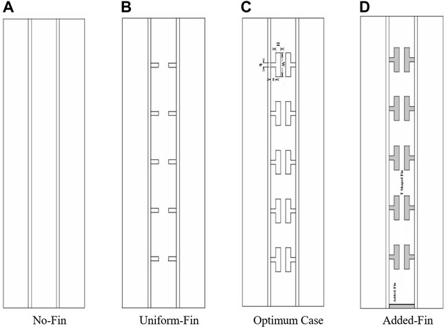
FIGURE 1. A schematic of the proposed systems under axisymmetric conditions. (A) No-Fin, (B) Uniform-Fin, (C) Optimum Case, (D) Added-Fin.
The dimensions of the T-shaped fins are presented in Table 1 for the system with T-shaped fins with and without considering the added fin. Moreover, in all cases, including T-shaped Fin and Uniform-Fin cases, the total volume of the fins is considered constant. Note that for the system with T-shaped fins and added fins, the thickness of the added fin is equal to the thickness of the body part of the T-shaped fin.
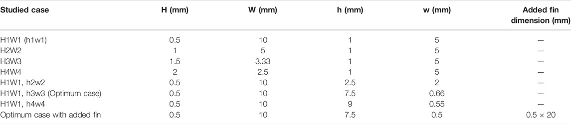
TABLE 1. The study cases including the dimensions of various T-shaped fins’ heads and bodies.
The dimensions of the triplex tube heat exchanger are selected based on the literature, which can be used in practical applications such as solar collectors and multiple tube heat storage systems (Sun et al., 2021; Najim et al., 2022). The dimensions proposed can also be considered as the whole or a section of a triple-tube heat storage unit. Accordingly, the heat exchanger length is 250 mm and the diameters of the interior, middle, and exterior pipes are 20, 40, and 60 mm, respectively. The pipe wall materials are cooper and pipe walls are equally fixed as 1 mm wide. HTF passes through the inner pipe in the opposite direction of gravity while HTF inside the outer pipe is circulated in the direction of gravity. The thermal performance of the proposed configuration is better than that of co-current directions for the fluid flow as discussed in previous studies. Therefore, the flow of HTF through the PCM casing is selected to be in a counter-current direction. The velocity and temperature of the HTF at the inlet section is constant while the boundary conditions for the HTF at the outlet section are selected to be at an outflow with constant velocity and temperature. A 3D view of the PCM heat exchanger case without a fin, the associated boundary conditions, and the dimensions of constituent pipes are illustrated in Figure 2. The inlet temperature and Reynolds number values for the HTF flow that are used to determine the optimal fin arrangement are 50 °C and 1,000, respectively. Furthermore, the initial temperature of the PCM during the heat charging mode is 15 °C.
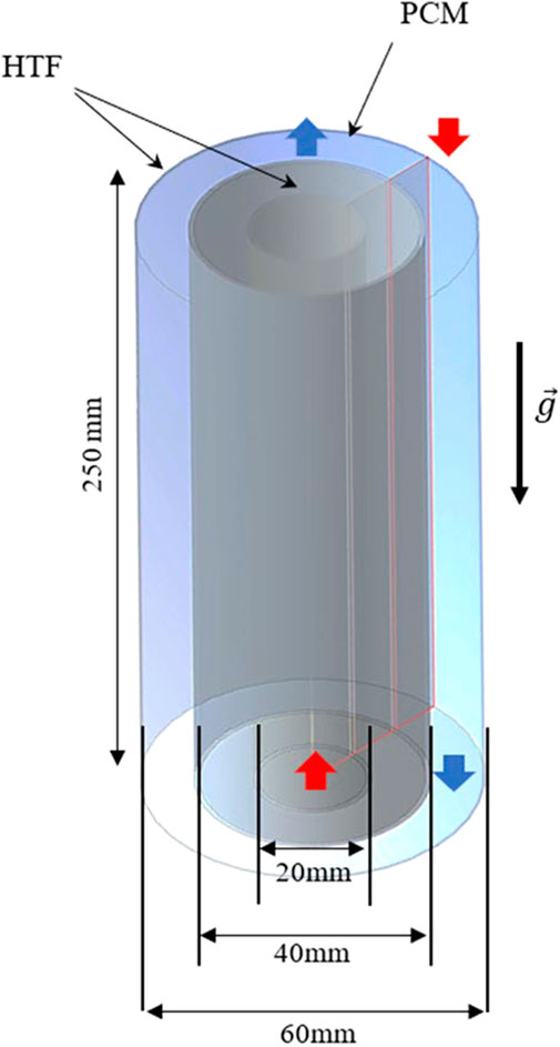
FIGURE 2. The triple-tube heat exchanger along with boundary conditions and dimensions for the No-Fin case.
The thermophysical characteristics of the PCM (paraffin RT-35) used in this study are shown in Table 2.

TABLE 2. Thermodynamic properties of the PCM used (Gmbh).
The enthalpy-porosity method proposed by Brent et al. (1988) was applied to numerically simulate the phase transition of PCM. Based on this approach, the porosity and liquid fraction were comparable within all computational domain’s cells. The following assumptions were considered to derive the governing equations:
• Variations of the density and buoyant force are determined using the Boussinesq approximation.
• The flow of PCM in the liquid phase is axisymmetric, incompressible, transient, and laminar.
• The direction of gravity acceleration is taken along the negative y-axis.
• The exterior boundaries are completely insulated, and as a result, the heat losses to the surroundings are neglected.
• The no velocity-slip boundary condition is considered at the solid boundaries.
The Navier-Stokes conservation equations for continuity, momentum, and energy can be written as follows (Wang et al., 2015):
The impact of phase transition defined as the velocity damping of the Darcy law is considered in Eq. 2 via the application of the term
Based on the previous publications (Ye et al., 2011; Mahdi and Nsofor, 2017), the value of the mushy zone
The density fluctuations due to temperature swings during the PCM’s phase transition course can be computed using the Boussinesq approximation. Using this approximation, fluid density is considered a temperature-dependent variable only in the gravity term of the momentum equation while it is constant for other sections:
The following equation can be applied to estimate the source term
Eq. 8 is developed to calculate the rate of energy stored during the melting phase period:
where the total values of heat storage of the PCM upon starting and ending the phase transition course are denoted by
To examine the thermofluidic features of the PCM during the heat charging process, the SIMPLE approach for the pressure-velocity coupling was integrated with a Green-Gauss cell-based meshing method in a modified ANSYS-FLUENT solver. Momentum and energy equations were then solved using the QUICK differencing method while the PRESTO approach was applied to solve the pressure correction equations. The values of under-relaxation parameters applied for velocity components, pressure correction, the energy equation, and liquid fraction were selected as 0.3, 0.3, 1.0, and 0.5, respectively, based on a comprehensive pre-selection process. The convergence requirements to stop the iterative solutions of the continuity, momentum, and energy equations at each time step were 10−4, 10−4, and 10−6, respectively.
Various cell numbers of 28,500, 43,000, and 81,620 with a timestep size of 0.2 s were considered in this study to conduct the grid and time step size independence tests for the straight triple-pipe casing of the PCM. Results of the grid and time step size independency tests are illustrated in Table 3. Based on Table 3, the values of melting time for grid sizes of 43,000 and 81,620 are approximately the same. Thus, the grid size of the mesh was selected as 43,000 in this study. Furthermore, the melting time values for various time step sizes are also illustrated in Table 3. Based on Table 3, the melting time for time step sizes of 0.1, 0.2, and 0.4 s are approximately the same. Therefore, the time step size was set to 0.2 s for the next analysis.
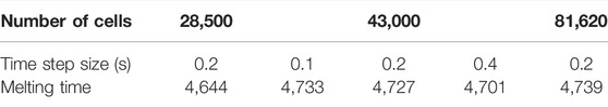
TABLE 3. The effect of cell number and time step size on the melting time.
The simulation model accuracy was evaluated by comparing the numerical results with those of Mat et al. (2013), where the thermal characteristics of RT58 as the PCM in a double-tube casing unit were both numerically and experimentally studied. Their research examined the effects of attaching fins to the interior and exterior tubes of the PCM shell in a staggered configuration while the inner tube was subjected to a constant temperature. The numerical values, including the overall temperature of the PCM and the transient development of the liquid fraction obtained from this simulation model, are compared with those of Mat et al. (2013) in Figure 3. As shown from Figure 3, the numerical results of this model agree well with both the numerical and experimental results of Mat et al. (2013). The statistical validation provides a maximum percentage error of 1.4%. Thus, this model can be adopted to explore the thermal characteristics of the PCM-based triple-tube system in the presence of fins. Of note, the experimental uncertainty in the study of Mat et al. (2013) is ± 0.15 °C (approximately 0.2%) for the temperature measurement.
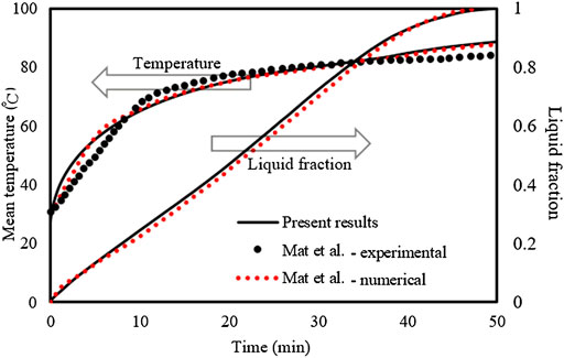
FIGURE 3. The simulation model’s predictions for temperature and the liquid fraction progress compared to those of Mat et al. (2013)
In this section, the effects of shape and size of T-shaped fins on the charging process of the PCM in a vertical triple-pipe heat exchanger are investigated. The PCM was included in the middle channel while the HTF flow of water passed through the internal and external channels to transfer heat to the PCM. The unit was axisymmetric (Figure 1) because of the uniformity of the circumferential flow. Five fins were positioned at the inner and outer walls of the middle channel (10 fins in total) to improve the heat transfer rate to the PCM. The HTF flowed in the opposite direction in the inner (opposite the direction of gravity) and outer channels (in the direction of gravity). For the different cases studied, the mass of the PCM was kept the same to create an accurate comparison. The first part of this study investigated the influences of four different dimensions of the head of the T-shaped fins (the thickness of the head (H) and width of the head (W) (0.5 mm × 10 mm), (1 mm × 5 mm), (1.5 mm × 3.33 mm), and (2 mm × 2.5 mm)) with a fixed dimension of the fin’s body. In the second part, the effects of the different body dimensions of the T-shaped fins (length and the width of the body (w and h) (5 mm × 1 mm), (2 mm × 2.5 mm), (0.66 mm × 7.5 mm), and (0.55 mm × 9 mm)) were combined with the best dimension of the head fin that was found in the first part as illustrated in Figure 1A and Table 1. Then, the efficiency of the best-optimized unit was compared with the case of the best T-shaped fin integrated with a flat fin at the bottom of the channel (Figure 1D), the Uniform-Fin case (Figure 1B,) and the No-Fin case (Figure 1A). The major emphasis of this work was to investigate the pertinence of T-shaped fins to offer the best saving function in PCM-based systems. Furthermore, many studies on the double and triple-tube storage system with and without circular or longitudinal fins have been extensively completed to enhance the efficiency of such a unit. This article develops an additional aspect to the other studies in the literature regarding the competent finned triple-tube energy storage unit using T-shaped fins. Table 1 shows the cases and dimensions considered in this study.
Integrating fins into the thermal energy storage system enhances the efficiency of the unit for the following reasons: 1) it increases the average thermal conductivity of the entire system due to the high thermal conductivity of the fins material compared to the PCM; 2) it enlarges the heat exchange surface area and increases the heat transfer rate from the fins to the PCM; 3) it transfers heat to other regions of the PCM zone and helps the solid PCM become molten at those regions; and 4) the molten phase (caused by the fins) improves the free convection process. Four different dimensions of the fin’s head (as shown in Table 1) are examined in this section with a fixed dimension of the fin’s body (h is 1 mm and w is 5 mm). The Optimum case was selected by analyzing the contours of the liquid fraction and the temperature, heat storage rate, melting time, and the development of the average temperature.
Figure 4 shows the liquid fraction development at different times for various dimensions of the T-shaped fin’s head (with a similar size to the fins body). The behavior of the melting process is nearly similar in all cases presented in Figure 4 while the only difference is the dimension of the T-shaped fins head. The reason for the minor effect of the T-shaped fin’s head on the melting process returns to the vertical orientation of those parts on the one hand, and the small connection area of the body to the fin head on the other hand, which limits the heat transfer rate from the fin body to the fin head. Initially, the adjoined PCM to the walls and the fins are molten as shown from the liquid fraction contour at 600 s. The molten area expands, and the solid area between the two inline fins confines and separates. Within the 1800 s, the only solid states that remain are small portions at the center of the regions between fins, and these portions become smaller by moving up from the region between the fins and then disappear at the top region. This is because of the circulation of the liquid phase due to free convection, which collects the liquid state at the top of the system. In all cases, the entire system melts within 2,400 s except the bottom part of the heat exchanger channel due to the Boussinesq effect.
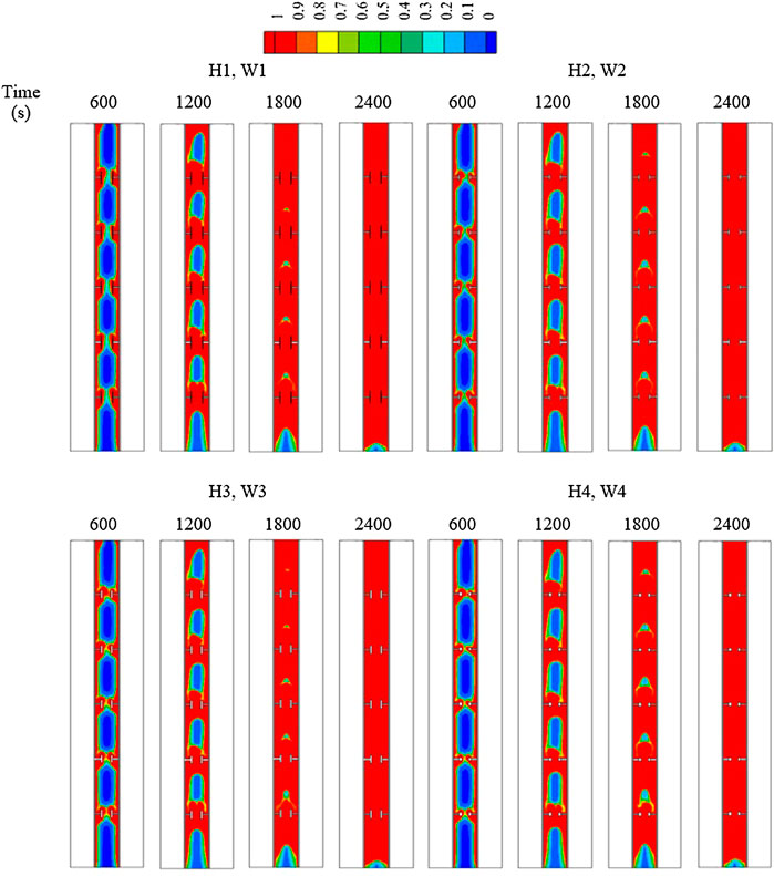
FIGURE 4. The liquid fraction development for various dimensions of the T-shaped fins heads at various times (the sizes of the fin’s body are the same).
Figure 5 shows the temperature contours of the system for different cases of the fin’s head. As previously discussed, the behavior of the temperature distribution are approximately the same for all cases. The temperature of the HTF is red and shows the highest temperature value in the system. The temperature increases in the regions adjacent to the walls and around the fins. The area at the top of each region between the fins reaches a thermal equilibrium state with the HTF channel first, and at 2,400 s the entire system reaches thermal equilibrium except for the bottom part of the channel, which needs more time to melt.
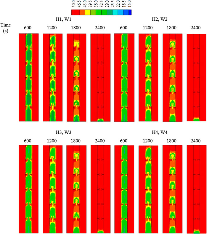
FIGURE 5. The temperature distribution for various dimensions of the T-shaped fins heads at various times (the sizes of the fin’s body are the same).
Figure 6A shows the heat storage rate and total melting time for all dimensions of the fin head. Figure 6A shows that the heat storage rates are nearly the same (55–56.8 W) for all cases. Although the total melting times for all cases are approximately similar based on Figure 6B, case H1W1 had the lowest total melting time. The highest total melting was recorded for the case of H4W4 among the other cases. This indicates that the melting process of the PCM is not dependent on the head dimension of the T-shaped fins. The vertical orientation of the head fin, with a small connection area to the body of the fin transferring heat from the fin body to the fin head, are the main reasons for minor differences between cases.
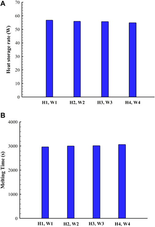
FIGURE 6. (A) Heat storage rate; (B) melting time for various dimensions of the T-shaped fins head (the sizes of the fins body are the same).
Figure 7 shows variations of the liquid fraction and the average temperature versus time. The melting times for all cases investigated are approximately the same while case H1W1 benefits from a small advantage over the other cases. The temperature also shows similar behavior to reach thermal equilibrium (Figure 7B). After 1800 s, there is a change in the slope or path of the curves caused by the free convection that results from the melting process of the solid PCM (Figure 7B).
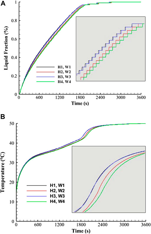
FIGURE 7. (A) Liquid fraction development; (B) temperature profile for various dimensions of the T-shaped fin’s head (the sizes of the fin’s body are the same).
Table 4 shows heat storage rates and melting times for the study cases. The heat storage rate of case H1W1 was the highest. In addition, the heat storage rate of case H1W1 increased by 1.4%, 1.8%, and 3.3% compared to those of cases H2W2, H3W3, and H4W4, respectively. The total melting time of case H1W1 decreased by 1.4%, 1.8%, and 3.3% compared to those of cases H2W2, H3W3, and H4W4, respectively. Although these differences between the cases are negligible, case H1W1 was selected for further analyses due to its relatively better performance.
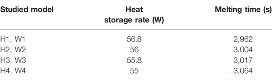
TABLE 4. The total heat storage rates and the melting times for various dimensions of the T-shaped fin’s head (the sizes of the fin’s body are the same).
Effects of the different sizes of the fin’s body are studied in this section for case H1W1 and shows the best performance. The different dimensions of the fin’s body are considered in this work [(5 mm × 1 mm), (2 mm × 2.5 mm), (0.66 mm × 7.5 mm), and (0.55 mm × 9 mm)]. Figure 8 shows the liquid fraction of the PCM at different times for various dimensions of the fin’s body. Based on Figure 8, the melting process starts in the regions besides the wall and around the fins. The solid state of the PCM remains in the regions confined between the inline fins at the early time of the melting process, but the solid part gradually melted. The melting process was affected by the length of the fin’s body; the longer the body, the faster the melting period due to the higher surface area of longer fins. In case h4w4 (the case with the longest fin body), the gap between the two inline fins is too tiny, which causes a negative impact on the overall melting process. Therefore, case h3w3 shows a better performance in this regard.
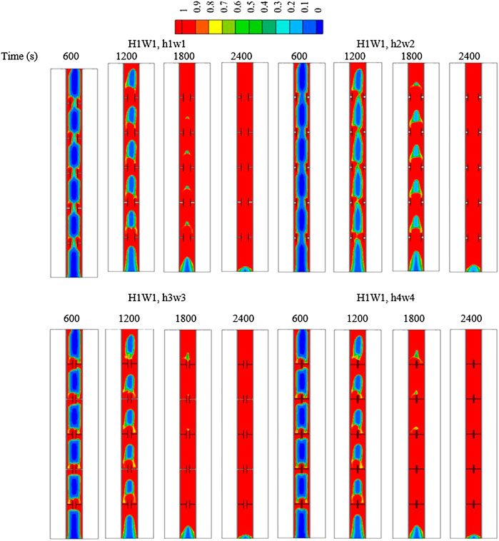
FIGURE 8. The liquid fraction development for various dimensions of the T-shaped fin’s body at various times [with the same size of the fin’s head (H1, W1)].
The temperature distributions for the cases of various fin bodies are illustrated in Figure 9. The temperature of the HTF is fixed at 50 °C and the temperature of the PCM gradually increases in the regions adjacent to the walls and around the fins. The average temperature of the PCM increases rapidly within the first 600 s due to the thermal conductivity of the PCM. The warm regions are focused at the top of each region between the inline fins. Within 2,400 s, the average temperature reached 48 °C for case h1w1 and it reached more than 49 °C for the other cases.
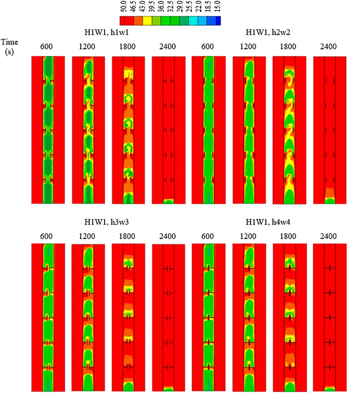
FIGURE 9. The temperature distribution for various dimensions of the T-shaped fin’s body at various times [with the same size of the fin’s head (H1, W1)].
Figure 10 shows heat storage rates and melting times for all cases studied. Figure 10A shows that case h3w3 had a slightly better performance than the other cases. The heat storage rate ranged between (56–59 W). Case h3w3 also had the lowest melting time among the other cases (2836 s). However, the highest melting time was recorded for case h2w2 based on Figure 10B. The difference in the melting time originated from the length of the fin’s body as longer fins provided a higher surface area and consequently faster melting.
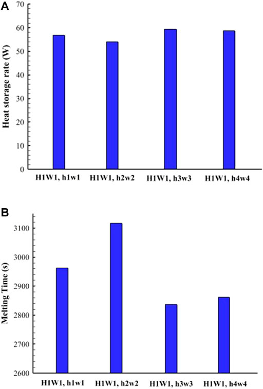
FIGURE 10. (A) Heat storage rate; (B) melting time for various dimensions of the T-shaped fin’s body [with the same size of the fin’s head (H1W1)].
Figure 11 shows the liquid fraction and average temperature development for different cases of the fin’s body dimensions. Figure 11A shows variations of liquid fraction development versus time during the melting process. For all cases, the melting process sharply increased because of the thermal conductivity and high heat transfer rate due to the fin’s presence. Longer fins provide a larger surface area, and consequently, a faster charging process. Case h2w2 showed a slower phase change process. Figure 11B shows the mean temperature variations versus time for all cases of the fin’s body. Figure 11B shows that the temperature increased sharply at the beginning of the process due to the thermal conductivity effect of the PCM. The rising rate of the temperature is reduced due to the molten phase, which enhances the impact of free convection compared to that of conduction heat transfer.
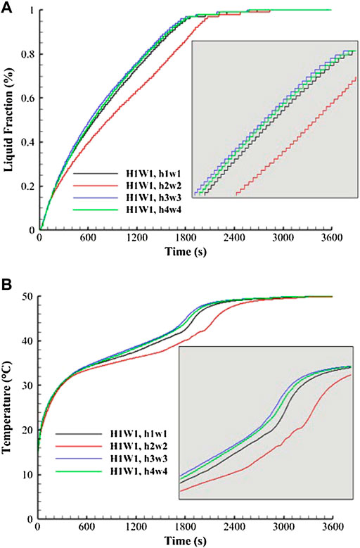
FIGURE 11. (A) Liquid fraction development; (B) temperature profile for various dimensions of the T-shaped fin’s body [with the same size of the fin’s head (H1W1)].
Table 5 shows that the best body length of the T-shaped fins was h3w3 (0.66 mm × 7.5 mm) in regard to the heat storage rate (59.3 W) and melting time (2,836 s). The heat storage rate of case h3w3 increased by 4.4%, 9.8%, and 0.9% compared with that of cases h1w1, h2w2, and h4w4, respectively. Likewise, the melting time of case h3w3 was the shortest among the other cases and the total melting time of case h3w3 decreased by 4.3%, 9%, and 0.9% compared with those of cases h1w1, h2w2, and h4w4, respectively.
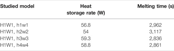
TABLE 5. The total heat storage rate and melting time for various dimensions of the T-shaped fins body [with a similar size to the fin’s head (H1W1)].
The best case study of the T-shaped fin’s system regarding the heat storage rate and melting time was H1W1, h3w3. For further investigations, this case was compared with the No-Fin case, Uniform-Fin case, and the Optimized case integrated with a flat fin at the bottom of the PCM container (Added-Fin).
In this section, the T-shaped fin case H1W1, h3w3 (Optimum case) is compared with the cases of the No-Fin, Uniform-Fin, and Added-Fin cases since the fin at the bottom of the PCM container accelerates the melting process. Figure 12 shows the development of the liquid fraction for all of the previously mentioned cases. Regarding the No-Fin case, the region adjacent to the wall melted first. The molten phase gradually expanded and the liquid phase was collected at the top of the system at t = 1,200 s. The molten phase reached 80% within 2,400 s. Overall, utilizing fins changed the behavior of the melting process; as the fins increased the thermal conductivity of the system and transferred heat to the PCM more uniformly, the phase change process occurred faster. The melting process began in the regions adjacent to the wall and around the fins at initial times for the Uniform-Fin case, and the liquid phase expanded and accumulated at the top regions between the inline fins. Within 2,400 s, the molten ratio was 97%. As previously explained, the T-shaped fins accelerated the melting process. Although the surface area of the T-shaped fin was higher than that of the Uniform-Fin case, the vertical orientation of the head part and the small connection area between the body and the head of the fin slightly improved the phase change process, especially at the bottom region of the system where the phase change process hardly occurred. To treat this issue, a flat fin was added to the bottom of the PCM container to completely melt the PCM within 2,400 s.
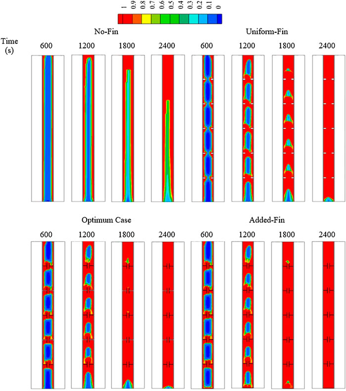
FIGURE 12. The liquid fraction development for various cases of No-Fin, Uniform-Fin, Optimum, and Added-Fin cases at various times.
The temperature distributions of various cases, including No-Fin, Uniform-Fin, Optimum case [T-shaped fin (H1W1-h3w3)], and Added-Fin (Optimum T-shaped Fin integrated with a flat fin at the bottom of the PCM container), are illustrated in Figure 13. The temperature of the PCM increased rapidly due to the effect of heat transfer based on Figure 13. The rate of increase is reduced as a layer of the liquid is created beside the walls and generates a thermal convection process. The temperature reached 39.5 °C within 2,400 s. The average temperature increased to 48.5 °C within a similar period in the presence of the uniform fins. Thermal equilibrium was observed in all parts except for the bottom of the system. Using the T-shaped fins increased the average temperature of the PCM to 49.5 °C since a part of the PCM at the base of the system did not reach the thermal equilibrium. Adding a flat fin to the bottom part of the unit helped the PCM to become entirely molten, and subsequently, the temperature reached the thermal equilibrium within 2,400 s.
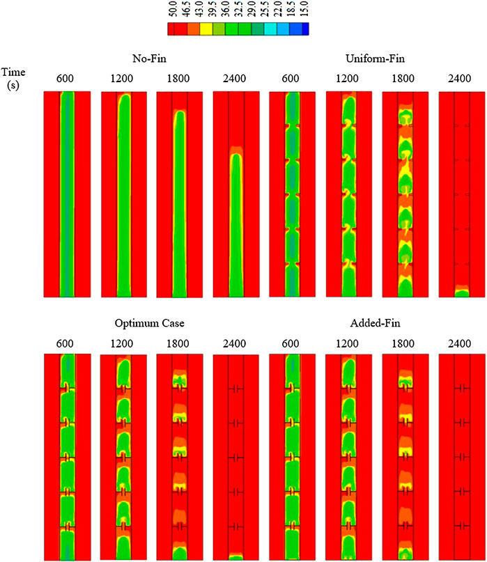
FIGURE 13. Temperature distribution for various cases of No-Fin, Uniform-Fin, Optimum, and Added-Fin cases at various times.
Although the Optimum case showed a better performance than the Uniform-Fin and the No-Fin cases regarding the heat storage rate and the melting time, the thermal performance of the Optimum case was lower than that of the Added-Fin case as shown in Figure 14. Adding a flat fin to the bottom of the system considerably affected the thermal performance. The performance improvement was maximized if the storage rate of the Added-Fin case was compared with that of the No-Fin case, whereas the increase of the heat storage rate was 141.7%.
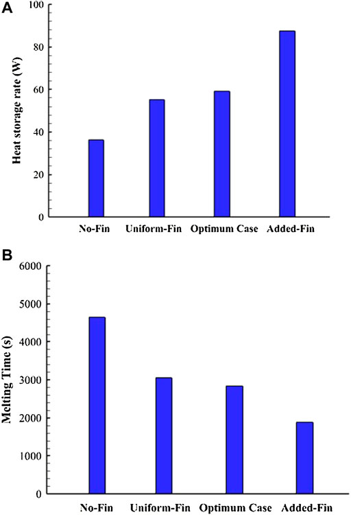
FIGURE 14. (A) Heat storage rate; (B) melting time for various cases of No-Fin, Uniform-Fin, Optimum, and Added-Fin cases.
Figure 15A shows the liquid fraction profile for the No-Fin, Uniform-Fin, Optimum and Added-Fin cases. The No-Fin case showed a logarithmic behavior but did not reach the total melting level even at 3,600 s. The Added-Fin case showed an advantage over the other cases, and the temperature increased in all cases sharply due to the conduction process. When the molten phase increased in the system, the slope of all curves changed due to the convection effect. Rising the temperature was the highest for the Added-Fin case and the lowest for the No-Fin case (As shown in Figure 15B).
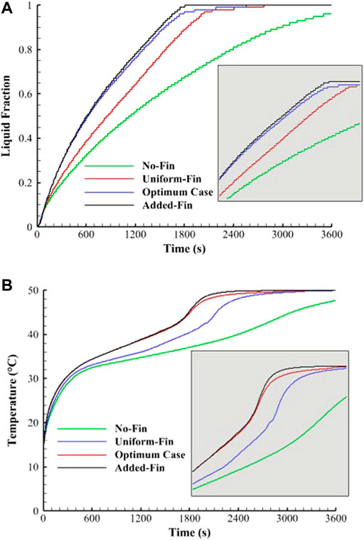
FIGURE 15. (A) Liquid fraction development; (B) temperature profile for various cases of No-Fin, Uniform-Fin, Optimum, and Added-Fin cases.
Table 6 shows the values of the heat storage rate and melting time for the last four cases. The heat storage rate was the highest for the Added-Fin case and increased by 141.7%, 58.8%, and 47.6% compared with that of the No-Fin, Uniform-Fin, and the Optimum cases, respectively. The total melting time of the Added-Fin case was 1882 s and decreased by 59.6%, 38.4%, and 33.6% compared with those of the No-Fin, Uniform-Fin, and Optimum cases, respectively.
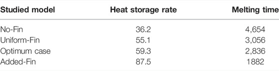
TABLE 6. The total heat storage rate and melting time for various cases of No-Fin, Uniform-Fin, Optimum case, and Added-Fin.
In this study, T-shaped fins were proposed to improve the melting process of PCM in a vertical triple-tube heat exchanger. First, the dimension effects of the T-shaped fins head on the liquid fraction development, temperature distribution, melting time, and heat storage rate of the PCM were evaluated to find the Optimum case. Second, the dimension effects of the T-shaped fin’s body on the liquid fraction development, temperature distribution, melting time, and heat storage rate of the PCM were also studied while the dimension of the T-shaped fin head was constant and equal to that of the Optimum case determined in the previous step. Furthermore, a flat fin was added at the bottom of the PCM container to improve the phase change phenomenon of PCM in a vertical triple-tube heat exchanger. Finally, the following conclusions were drawn:
• Although the dimension effects of the T-shaped fin head on the thermal performance of PCM were minor, the body dimensions of the T-shaped fin on the thermal characteristics of the system were major.
• Adding a flat fin to the bottom of the system considerably affected the thermal performance and resulted in a lower melting time.
• The heat storage rate of the best T-shaped configuration with an Added-Fin to the bottom increased by 141.7%, 58.8%, and 47.6% compared with those of the No-Fin, Uniform-Fin, and Optimum T-shaped Fin cases, respectively.
• The total melting time of the best T-shaped configuration with an Added-Fin to the bottom was 1882 s, and decreased by 59.6%, 38.4%, and 33.6% compared with those of the No-Fin, Uniform-Fin, and Optimum T-shaped Fin cases, respectively.
The original contributions presented in the study are included in the article/supplementary material, and further inquiries can be directed to the corresponding author.
Conceptualization, PT; methodology, MET and PT; software, JM and PT; validation, PT; formal analysis, MET, HM, RI, AD, JM, HM, and PT; investigation, MET, HM, RI, AD, JM, HM, MMK, and PT; writing—original draft preparation, MET, HM, RI, AD, JM, HM, MMK, and PT; writing—review and editing, MET, HM, RI, AD, JM, HM, MMK, and PT; supervision, PT; All authors have read and agreed to the published version of this manuscript.
The authors declare that this research was conducted in the absence of any commercial or financial relationships that could be construed as a potential conflict of interest.
All claims expressed in this article are solely those of the authors and do not necessarily represent those of their affiliated organizations or those of the publisher, editors, and reviewers. Any product that may be evaluated in this article, or claim that may be made by its manufacturer, is not guaranteed or endorsed by the publisher.
Abdulateef, A. M., Abdulateef, J., Mat, S., Sopian, K., Elhub, B., and Mussa, M. A. (2018). Experimental and Numerical Study of Solidifying Phase-Change Material in a Triplex-Tube Heat Exchanger with Longitudinal/triangular Fins. Int. Commun. Heat Mass Transf. 90, 73–84. doi:10.1016/j.icheatmasstransfer.2017.10.003
Alizadeh, M., Hosseinzadeh, K., Shahavi, M. H., and Ganji, D. D. (2019). Solidification Acceleration in a Triplex-Tube Latent Heat Thermal Energy Storage System Using V-Shaped Fin and Nano-Enhanced Phase Change Material. Appl. Therm. Eng. 163, 114436. doi:10.1016/j.applthermaleng.2019.114436
Anqi, A. E., Li, C., Dhahad, H. A., Sharma, K., Attia, E.-A., Abdelrahman, A., et al. (2022). Effect of Combined Air Cooling and Nano Enhanced Phase Change Materials on Thermal Management of Lithium-Ion Batteries. J. Energy Storage 52, 104906. doi:10.1016/j.est.2022.104906
Brent, A. D., Voller, V. R., and Reid, K. J. (1988). Enthalpy-porosity Technique for Modeling Convection-Diffusion Phase Change: Application to the Melting of a Pure Metal. Numer. Heat. Transf. 13, 297–318. doi:10.1080/10407788808913615
Chamkha, A. J., Doostanidezfuli, A., Izadpanahi, E., and Ghalambaz, M. (2017). Phase-change Heat Transfer of Single/hybrid Nanoparticles-Enhanced Phase-Change Materials over a Heated Horizontal Cylinder Confined in a Square Cavity. Adv. Powder Technol. 28, 385–397. doi:10.1016/j.apt.2016.10.009
Ejaz, A., Babar, H., Ali, H. M., Jamil, F., Janjua, M. M., Fattah, I. M. R., et al. (2021). Concentrated Photovoltaics as Light Harvesters: Outlook, Recent Progress, and Challenges. Sustain. Energy Technol. Assessments 46, 101199. doi:10.1016/j.seta.2021.101199
Elmaazouzi, Z., El Alami, M., Gounni, A., and Bennouna, E. G. (2020). Thermal Energy Storage with Phase Change Materials: Application on Coaxial Heat Exchanger with Fins. Mater. Today Proc. 27, 3095–3100. doi:10.1016/j.matpr.2020.03.653
Esapour, M., Hosseini, M. J., Ranjbar, A. A., Pahamli, Y., and Bahrampoury, R. (2016). Phase Change in Multi-Tube Heat Exchangers. Renew. Energy 85, 1017–1025. doi:10.1016/j.renene.2015.07.063
Fan, L.-W., Zhu, Z.-Q., Xiao, S.-L., Liu, M.-J., Lu, H., Zeng, Y., et al. (2016). An Experimental and Numerical Investigation of Constrained Melting Heat Transfer of a Phase Change Material in a Circumferentially Finned Spherical Capsule for Thermal Energy Storage. Appl. Therm. Eng. 100, 1063–1075. doi:10.1016/j.applthermaleng.2016.02.125
Gao, T., Li, C., Zhang, Y., Yang, M., Jia, D., Jin, T., et al. (2019). Dispersing Mechanism and Tribological Performance of Vegetable Oil-Based CNT Nanofluids with Different Surfactants. Tribol. Int. 131, 51–63. doi:10.1016/j.triboint.2018.10.025
Ghalambaz, M., Hashem Zadeh, S. M., Mehryan, S. A. M., Pop, I., and Wen, D. (2020a). Analysis of Melting Behavior of PCMs in a Cavity Subject to a Non-uniform Magnetic Field Using a Moving Grid Technique. Appl. Math. Model. 77, 1936–1953. doi:10.1016/j.apm.2019.09.015
Ghalambaz, M., Mehryan, S. A. M., Hajjar, A., and Veismoradi, A. (2020b). Unsteady Natural Convection Flow of a Suspension Comprising Nano-Encapsulated Phase Change Materials (NEPCMs) in a Porous Medium. Adv. Powder Technol. 31, 954–966. doi:10.1016/j.apt.2019.12.010
Ghalambaz, M., and Zhang, J. (2020). Conjugate Solid-Liquid Phase Change Heat Transfer in Heatsink Filled with Phase Change Material-Metal Foam. Int. J. Heat Mass Transf. 146, 118832. doi:10.1016/j.ijheatmasstransfer.2019.118832
Gmbh RT35 Data Sheet [Online]. Available at: https://www.rubitherm.eu ([Accessed]).
Guo, J., Liu, Z., Yang, B., Yang, X., and Yan, J. (2022). Melting Assessment on the Angled Fin Design for a Novel Latent Heat Thermal Energy Storage Tube. Renew. Energy 183, 406–422. doi:10.1016/j.renene.2021.11.007
Ho, C. J., Liu, Y.-C., Ghalambaz, M., and Yan, W.-M. (2020). Forced Convection Heat Transfer of Nano-Encapsulated Phase Change Material (NEPCM) Suspension in a Mini-Channel Heatsink. Int. J. Heat Mass Transf. 155, 119858. doi:10.1016/j.ijheatmasstransfer.2020.119858
Hosseini, M. J., Rahimi, M., and Bahrampoury, R. (2015). Thermal Analysis of PCM Containing Heat Exchanger Enhanced with Normal Annular Fines. Mech. Sci. 6, 221–234. doi:10.5194/ms-6-221-2015
Ju, Y., Zhu, T., Mashayekhi, R., Mohammed, H. I., Khan, A., Talebizadehsardari, P., et al. (2021). Evaluation of Multiple Semi-twisted Tape Inserts in a Heat Exchanger Pipe Using Al2O3 Nanofluid. Nanomaterials 11 (6), 1570. doi:10.3390/nano11061570
Li, B., Li, C., Zhang, Y., Wang, Y., Jia, D., and Yang, M. (2016). Grinding Temperature and Energy Ratio Coefficient in MQL Grinding of High-Temperature Nickel-Base Alloy by Using Different Vegetable Oils as Base Oil. Chin. J. Aeronautics 29, 1084–1095. doi:10.1016/j.cja.2015.10.012
Li, B., Li, C., Zhang, Y., Wang, Y., Jia, D., Yang, M., et al. (2017). Heat Transfer Performance of MQL Grinding with Different Nanofluids for Ni-Based Alloys Using Vegetable Oil. J. Clean. Prod. 154, 1–11. doi:10.1016/j.jclepro.2017.03.213
Liu, X., Mohammed, H. I., Ashkezari, A. Z., Shahsavar, A., Hussein, A. K., and Rostami, S. (2020). An Experimental Investigation on the Rheological Behavior of Nanofluids Made by Suspending Multi-Walled Carbon Nanotubes in Liquid Paraffin. J. Mol. Liq. 300, 112269. doi:10.1016/j.molliq.2019.112269
Mahdi, J. M., Mohammed, H. I., Hashim, E. T., Talebizadehsardari, P., and Nsofor, E. C. (2020). Solidification Enhancement with Multiple PCMs, Cascaded Metal Foam and Nanoparticles in the Shell-And-Tube Energy Storage System. Appl. Energy 257, 113993. doi:10.1016/j.apenergy.2019.113993
Mahdi, J. M., and Nsofor, E. C. (2017). Melting Enhancement in Triplex-Tube Latent Thermal Energy Storage System Using Nanoparticles-Fins Combination. Int. J. Heat Mass Transf. 109, 417–427. doi:10.1016/j.ijheatmasstransfer.2017.02.016
Mat, S., Al-Abidi, A. A., Sopian, K., Sulaiman, M. Y., and Mohammad, A. T. (2013). Enhance Heat Transfer for PCM Melting in Triplex Tube with Internal-External Fins. Energy Convers. Manag. 74, 223–236. doi:10.1016/j.enconman.2013.05.003
Mehryan, S. A. M., Vaezi, M., Sheremet, M., and Ghalambaz, M. (2020). Melting Heat Transfer of Power-Law Non-newtonian Phase Change Nano-Enhanced N-Octadecane-Mesoporous Silica (MPSiO2). Int. J. Heat Mass Transf. 151, 119385. doi:10.1016/j.ijheatmasstransfer.2020.119385
Naghavi, M. S., Metselaar, H. S. C., Ang, B. C., Zamiri, G., Esmailzadeh, A., and Nasiri-Tabrizi, B. (2021). A Critical Assessment on Synergistic Improvement in PCM Based Thermal Batteries. Renew. Sustain. Energy Rev. 135, 110259. doi:10.1016/j.rser.2020.110259
Najim, F. T., Mohammed, H. I., Al-Najjar, H. M. T., Thangavelu, L., Mahmoud, M. Z., Mahdi, J. M., et al. (2022). Improved Melting of Latent Heat Storage Using Fin Arrays with Non-uniform Dimensions and Distinct Patterns. Nanomaterials 12, 403. doi:10.3390/nano12030403
Peng, H., Zhang, D., Ling, X., Li, Y., Wang, Y., Yu, Q., et al. (2018). n-Alkanes Phase Change Materials and Their Microencapsulation for Thermal Energy Storage: A Critical Review. Energy fuels. 32, 7262–7293. doi:10.1021/acs.energyfuels.8b01347
Rahimi, M., Ranjbar, A. A., Ganji, D. D., Sedighi, K., and Hosseini, M. J. (2014). Experimental Investigation of Phase Change inside a Finned-Tube Heat Exchanger. J. Eng. 2014, 641954. doi:10.1155/2014/641954
Ren, L., Zhou, S., Peng, T., and Ou, X. (2021). A Review of CO2 Emissions Reduction Technologies and Low-Carbon Development in the Iron and Steel Industry Focusing on China. Renew. Sustain. Energy Rev. 143, 110846. doi:10.1016/j.rser.2021.110846
Said, Z., Arora, S., Farooq, S., Sundar, L. S., Li, C., and Allouhi, A. (2022a). Recent Advances on Improved Optical, Thermal, and Radiative Characteristics of Plasmonic Nanofluids: Academic Insights and Perspectives. Sol. Energy Mater. Sol. Cells 236, 111504. doi:10.1016/j.solmat.2021.111504
Said, Z., Ghodbane, M., Boumeddane, B., Tiwari, A. K., Sundar, L. S., Li, C., et al. (2022b). Energy, Exergy, Economic and Environmental (4E) Analysis of a Parabolic Trough Solar Collector Using MXene Based Silicone Oil Nanofluids. Sol. Energy Mater. Sol. Cells 239, 111633. doi:10.1016/j.solmat.2022.111633
Said, Z., Sundar, L. S., Rezk, H., Nassef, A. M., Chakraborty, S., and Li, C. (2021). Thermophysical Properties Using ND/water Nanofluids: An Experimental Study, ANFIS-Based Model and Optimization. J. Mol. Liq. 330, 115659. doi:10.1016/j.molliq.2021.115659
Shen, Z.-G., Chen, S., and Chen, B. (2022). Heat Transfer Performance of a Finned Shell-And-Tube Latent Heat Thermal Energy Storage Unit in the Presence of Thermal Radiation. J. Energy Storage 45, 103724. doi:10.1016/j.est.2021.103724
Silakhori, M., Metselaar, H. S. C., Mahlia, T. M. I., Fauzi, H., Baradaran, S., and Naghavi, M. S. (2014). Palmitic Acid/polypyrrole Composites as Form-Stable Phase Change Materials for Thermal Energy Storage. Energy Convers. Manag. 80, 491–497. doi:10.1016/j.enconman.2014.01.023
Sun, X., Mohammed, H. I., Tiji, M. E., Mahdi, J. M., Majdi, H. S., Wang, Z., et al. (2021). Investigation of Heat Transfer Enhancement in a Triple Tube Latent Heat Storage System Using Circular Fins with Inline and Staggered Arrangements. Nanomaterials 11 (10), 2647. doi:10.3390/nano11102647
Tang, S.-Z., Tian, H.-Q., Zhou, J.-J., and Li, H. (2021). Evaluation and Optimization of Melting Performance in a Horizontal Thermal Energy Storage Unit with Non-uniform Fins. J. Energy Storage 33, 102124. doi:10.1016/j.est.2020.102124
Tian, M., Yan, S., and Tian, X. (2019). Discrete Approximate Iterative Method for Fuzzy Investment Portfolio Based on Transaction Cost Threshold Constraint. Open Phys. 17, 41–47. doi:10.1515/phys-2019-0005
Tiari, S., and Hockins, A. (2021). An Experimental Study on the Effect of Annular and Radial Fins on Thermal Performance of a Latent Heat Thermal Energy Storage Unit. J. Energy Storage 44, 103541. doi:10.1016/j.est.2021.103541
Tiari, S., Qiu, S., and Mahdavi, M. (2015). Numerical Study of Finned Heat Pipe-Assisted Thermal Energy Storage System with High Temperature Phase Change Material. Energy Convers. Manag. 89, 833–842. doi:10.1016/j.enconman.2014.10.053
Wang, P., Wang, X., Huang, Y., Li, C., Peng, Z., and Ding, Y. (2015). Thermal Energy Charging Behaviour of a Heat Exchange Device with a Zigzag Plate Configuration Containing Multi-Phase-Change-Materials (M-PCMs). Appl. Energy 142, 328–336. doi:10.1016/j.apenergy.2014.12.050
Wang, Y., Li, C., Zhang, Y., Yang, M., Li, B., Jia, D., et al. (2016). Experimental Evaluation of the Lubrication Properties of the Wheel/workpiece Interface in Minimum Quantity Lubrication (MQL) Grinding Using Different Types of Vegetable Oils. J. Clean. Prod. 127, 487–499. doi:10.1016/j.jclepro.2016.03.121
Wong, H. F., Ahmad, N., Siri, Z., and Noor, N. F. M. (2021a). Viscous Heating and Cooling Process in a Mixed Convection Cavity with Free-Slip Effect. Case Stud. Therm. Eng. 28, 101349. doi:10.1016/j.csite.2021.101349
Wong, H. F., Sohail, M., Siri, Z., and Noor, N. F. M. (2021b). Numerical Solutions for Heat Transfer of an Unsteady Cavity with Viscous Heating. Comput. Mater. Continua 68 (1), 319–336. doi:10.32604/cmc.2021.015710
Xin, C., Changhe, L., Wenfeng, D., Yun, C., Cong, M., Xuefeng, X., et al. (2021). Minimum Quantity Lubrication Machining of Aeronautical Materials Using Carbon Group Nanolubricant: from Mechanisms to Application. Chin. J. Aeronautics.
Yan, S.-R., Fazilati, M. A., Boushehri, R., Mehryaar, E., Toghraie, D., Nguyen, Q., et al. (2020). Experimental Analysis of a New Generation of Membrane Liquid Desiccant Air-Conditioning (LDAC) System with Free Convection of Desiccant for Energy Economic Management. J. Energy Storage 29, 101448. doi:10.1016/j.est.2020.101448
Yang, M., Li, C., Luo, L., Li, R., and Long, Y. (2021). Predictive Model of Convective Heat Transfer Coefficient in Bone Micro-grinding Using Nanofluid Aerosol Cooling. Int. Commun. Heat Mass Transf. 125, 105317. doi:10.1016/j.icheatmasstransfer.2021.105317
Yang, M., Li, C., Zhang, Y., Jia, D., Zhang, X., Hou, Y., et al. (2017). Maximum Undeformed Equivalent Chip Thickness for Ductile-Brittle Transition of Zirconia Ceramics under Different Lubrication Conditions. Int. J. Mach. Tools Manuf. 122, 55–65. doi:10.1016/j.ijmachtools.2017.06.003
Yang, X., Wang, X., Liu, Z., Luo, X., and Yan, J. (2021). Effect of Fin Number on the Melting Phase Change in a Horizontal Finned Shell-And-Tube Thermal Energy Storage Unit. Sol. Energy Mater. Sol. Cells 236, 111527. doi:10.1016/j.solmat.2021.111527
Ye, W.-B., Zhu, D.-S., and Wang, N. (2011). Numerical Simulation on Phase-Change Thermal Storage/release in a Plate-Fin Unit. Appl. Therm. Eng. 31, 3871–3884. doi:10.1016/j.applthermaleng.2011.07.035
Zhang, D., Li, C., Zhang, Y., Jia, D., and Zhang, X. (2015). Experimental Research on the Energy Ratio Coefficient and Specific Grinding Energy in Nanoparticle Jet MQL Grinding. Int. J. Adv. Manuf. Technol. 78, 1275–1288. doi:10.1007/s00170-014-6722-6
Zhang, S., Pu, L., Xu, L., Liu, R., and Li, Y. (2020). Melting Performance Analysis of Phase Change Materials in Different Finned Thermal Energy Storage. Appl. Therm. Eng. 176, 115425. doi:10.1016/j.applthermaleng.2020.115425
Zhang, Y., Li, C., Ji, H., Yang, X., Yang, M., Jia, D., et al. (2017). Analysis of Grinding Mechanics and Improved Predictive Force Model Based on Material-Removal and Plastic-Stacking Mechanisms. Int. J. Mach. Tools Manuf. 122, 81–97. doi:10.1016/j.ijmachtools.2017.06.002
Zhang, Y., Li, C., Jia, D., Zhang, D., and Zhang, X. (2015a). Experimental Evaluation of MoS2 Nanoparticles in Jet MQL Grinding with Different Types of Vegetable Oil as Base Oil. J. Clean. Prod. 87, 930–940. doi:10.1016/j.jclepro.2014.10.027
Zhang, Y., Li, C., Jia, D., Zhang, D., and Zhang, X. (2015b). Experimental Evaluation of the Lubrication Performance of MoS2/CNT Nanofluid for Minimal Quantity Lubrication in Ni-Based Alloy Grinding. Int. J. Mach. Tools Manuf. 99, 19–33. doi:10.1016/j.ijmachtools.2015.09.003
Zhou, S.-S., Almarashi, A., Talabany, Z. J., Selim, M. M., Issakhov, A., Li, Y.-M., et al. (2021). Augmentation of Performance of System with Dispersion of Nanoparticles inside PCM. J. Mol. Liq. 333, 115921. doi:10.1016/j.molliq.2021.115921
E (J) Heat storage
Solidus temperature
TES Thermal energy storage
PCM Phase change materials
LHS Latent heat storage
HTF Heat transfer fluid
LHTES Latent heat thermal energy storage
TTHX Triple-tube heat exchanger
ΔH (Jkg−1) PCM Latent heat
Lf (Jkg−1) Latent heat of fusion
Keywords: charging process, counter-current flow, heat transfer enhancement, thermal performance, T-shaped fins, phase change materials, thermal energy storage
Citation: Ebrahimnataj Tiji M, Mohammed HI, Ibrahem RK, Dulaimi A, Mahdi JM, Sh. Majdi H, Keshtkar MM and Talebizadehsardari P (2022) Evaluation of T-Shaped Fins With a Novel Layout for Improved Melting in a Triple-Tube Heat Storage System. Front. Energy Res. 10:947391. doi: 10.3389/fenrg.2022.947391
Received: 18 May 2022; Accepted: 20 June 2022;
Published: 23 August 2022.
Edited by:
Mahyar Silakhori, University of Adelaide, AustraliaReviewed by:
Alireza Esmaeilzadeh, University of Malaya, MalaysiaCopyright © 2022 Ebrahimnataj Tiji, Mohammed, Ibrahem, Dulaimi, Mahdi, Sh. Majdi, Keshtkar and Talebizadehsardari. This is an open-access article distributed under the terms of the Creative Commons Attribution License (CC BY). The use, distribution or reproduction in other forums is permitted, provided the original author(s) and the copyright owner(s) are credited and that the original publication in this journal is cited, in accordance with accepted academic practice. No use, distribution or reproduction is permitted which does not comply with these terms.
*Correspondence: Pouyan Talebizadehsardari, cG91eWFuLnRhbGViaXphZGVoc2FyZGFyaUBicnVuZWwuYWMudWs=
Disclaimer: All claims expressed in this article are solely those of the authors and do not necessarily represent those of their affiliated organizations, or those of the publisher, the editors and the reviewers. Any product that may be evaluated in this article or claim that may be made by its manufacturer is not guaranteed or endorsed by the publisher.
Research integrity at Frontiers
Learn more about the work of our research integrity team to safeguard the quality of each article we publish.