 Zhipeng Wang
 Jing Zhao
 Zishen Ye1,2,3
94% of researchers rate our articles as excellent or good
Learn more about the work of our research integrity team to safeguard the quality of each article we publish.
Find out more
ORIGINAL RESEARCH article
Front. Energy Res., 28 September 2022
Sec. Nuclear Energy
Volume 10 - 2022 | https://doi.org/10.3389/fenrg.2022.939712
This article is part of the Research TopicAdvanced Modeling and Simulation of Nuclear ReactorsView all 14 articles
Helium flow in the rod bundle channel with an open lattice structure is an important phenomenon for the advanced gas-cooled nuclear core design. In this study, thermal analysis with helium flow in various channel designs is conducted based on CFD methods to determine a dimension-optimized rod bundle channel. An experimental study then follows in order to pick up an appropriate gas flow model in further numerical simulation. Finally, helium flow in the bundle channels consisting of 217 rods is simulated using this chosen flow model, which shows to satisfy the requirements of basic thermal analysis of a newly designed gas-cooled reactor with an open lattice structure. Generally, this work will contribute to the design and analysis of the future advanced space nuclear power system.
A high-temperature gas-cooled reactor combined with a closed cycle magnetohydrodynamic (CCMHD) power generation system is a promising technology for space applications (Litchford et al., 2001a; Harada et al., 2006; Kugeler and Zhang, 2018; She et al., 2021). It can meet the requirements in space tasks for high power and high efficiency.
The system mainly comprise a nuclear reactor, an MHD generator, a regenerator, compressors, and a radiator, whose schematic of working medium operation is shown in Figure 1. Helium is adopted as both the coolant and the power generation medium for its good ionization properties and chemical inertness (Kobayashi and Okuno, 2000; Litchford et al., 2001b).
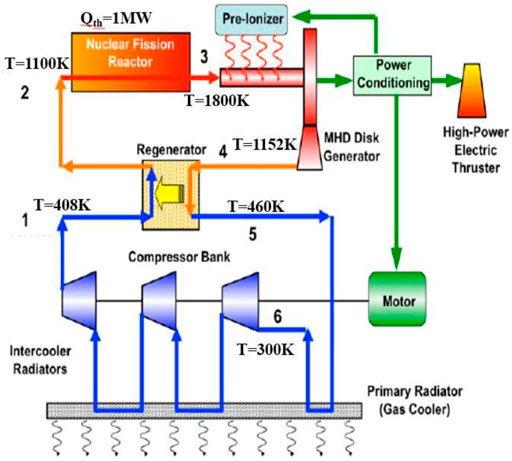
FIGURE 1. Schematic of working medium operation in the CCMHD system (Harada et al., 2006).
The thermodynamic models and mass models of this system were established in the previous research (Wang et al., 2019), and a set of design parameters suitable for 1-MW thermal power system was given, including the reactor inlet and outlet temperature and the operating pressure. As for the elaborate reactor design, it remains to be a new challenge to match with the CCMHD system. MJ Wollman proposed a series of gas-cooled reactor designs that can match the Brayton dynamic conversion system in the Prometheus Research Program (Taylor, 2005; Wollman and Zika (Apr, 2006), including open lattice design, pin in block design, and modular cermet design, as shown in Figure 2, which can provide some references for the reactor design in the CCMHD system. The pin in block design not only shows great convective heat transfer characteristics in the preliminary study but also displays a large pressure drop with helium flow. The modular cermet design requires further research and experimental verification because CERMET fuel has not been tested for long-term ultra-high temperature, and the manufacturing process is also very difficult (An et al., 2015; Zhao et al., 2018).

FIGURE 2. Geometrical options mentioned in the Prometheus Research Program (Wollman and Zika (Apr, 2006)).
Literally, the open lattice design has no flow block and provides the lowest mass geometry. Based on both the Prometheus open lattice structure and the Russian megawatt space reactor, Tao Meng designed a space gas-cooled reactor scheme composed of 534 fuel rods and 13 control rods. Through the flow and heat transfer simulation calculation of this scheme, conclusions were made that the reactor design had good thermal and hydraulic characteristics and can satisfy corresponding technical indexes (Meng et al., 2019; Meng et al., 2020).
Therefore, in this study, considering neutronics and thermal analysis, an initial feasible reactor core scheme based on the open lattice structure is presented without clarification in this first part. Sensibility analysis is then conducted to check the thermal hydraulic characteristics of the coolant flow in the open lattice structure, by means of changing the number of rods, the rod diameter, and the rod distance. After selecting a dimension-optimized rod bundle channel, an essential experiment concerning the open lattice structure is conducted, to pick up an appropriate gas flow model for further numerical simulation. In the last section, helium flow in the bundle channel with 217 rods is simulated using this determined flow model, to conduct more elaborate research on the new gas-cooled reactor with an open lattice structure.
A preliminary model including a number of triangle-deposited rods is put forward, which combines both neutronics analysis and thermal considerations. The integral reactor design and the coolant flow path are illustrated in Figure 3, whose basic parameters are summarized in Table 1.
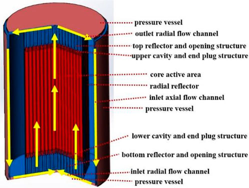
FIGURE 3. Schematic of the coolant flow path.
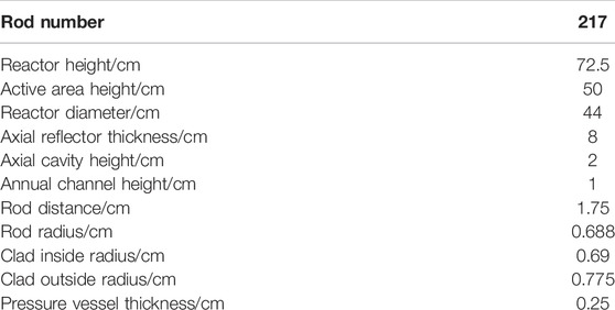
TABLE 1. Preliminary reactor design parameters.
In particular, the preliminary core structure and size are depicted in Figure 4A. Also, the diagram of 1/12 of the fuel layer among the reactor is shown in Figure 4B. Specifically, the fuel material is UN, the clad material is rhenium (Re), and the coolant is helium (He). The reflector material is BeO, and the pressure vessel material is a high temperature-resistant alloy MA-ODS956.
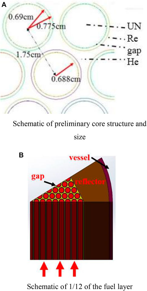
FIGURE 4. (A) Schematic of preliminary core structures and size. (B) Schematic of 1/12 of the fuel layer.
In the framework of given neutronics analysis, namely, fixing the reactor size and fuel installation, sensibility analysis is required to check thermal-hydraulic characteristics of the coolant flow in the open lattice structure, by means of changing the number of rods, the rod diameter, and the rod distance. Basic rules can be deduced qualitatively, while quantitative analysis is also indispensable in parameter optimization research. To simplify the calculation resources, in this section, only 1/12 of the individual channel is simulated and analyzed, as shown in Figure 5.
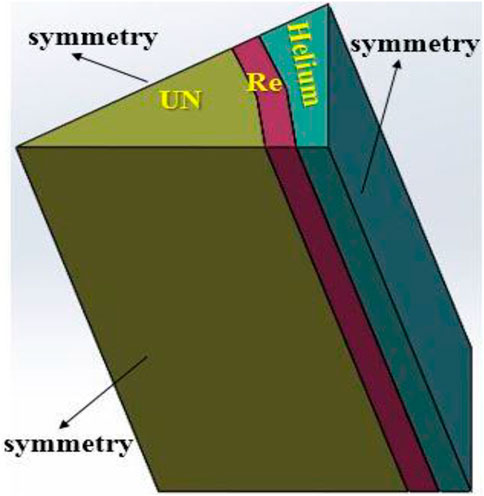
FIGURE 5. Schematic of 1/12 of the individual channel.
As optimized in the previous system performance analysis research (Wang et al., 2019), the inlet temperature is set at 1100 K, and the outlet temperature is 1800 K. In addition, the outlet pressure is 0.4 MPa. Additionally, the gap structure which lies between the fuel and the clad and the radiation effects inside the reactor are neglected here, which will be considered in Section 4.
The governing equations conforming to the conservation of mass, momentum, and energy are established under the framework of incompressible Navier–Stokes equations, which can be written as
where the variables with over-bar are the mean parameters, while the variables with prime are fluctuated values. Furthermore, the unclosed parameters
The purpose of this section is to optimize the fuel parameters, such as the number of rods, the rod diameter, and the rod distance, in the framework of given neutronics analysis, namely, fixing the reactor size and fuel installation. The total power of the reactor is 1 MW.
If the power density of the fuel is kept constant at 61.97 MW/m3, the fuel volume should be constant, which means the number of rods should be set inversely proportional to the square of the rod radius. Considering that the reactor size is fixed, the rod distance should be set inversely proportional to the number of rod turns. Mass flow rates can be deduced based on the conservation of energy. The calculation results of different number of rods are summarized in Table 2.
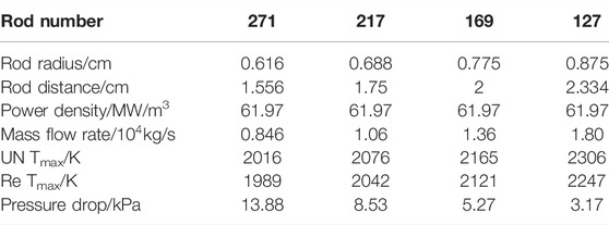
TABLE 2. Summary of simulated rod bundle parameters in power density fixed analysis.
It can be concluded that when the number of rods decreases, the rod radius increases to keep the power density at a constant level. The actual heat exchange area decreases, leading to decreased heat exchange capabilities and decreased pressure drop. Overall, 217 rods prevail for medium temperature and pressure drop limitations.
If the amount of the fuel is kept constant at 217, the rod distance should be constant to keep the reactor size constant. The power density should be set inversely proportional to the square of the rod radius, to keep the total power constant at 1 MW. Mass flow rates can be deduced based on the conservation of energy. The rod radius varies from 0.683 cm to 0.698 cm, which could hardly exercise effects on neutronics calculations. The calculation results of different rod radius are summarized in Table 3.
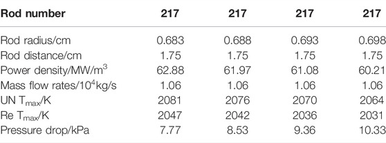
TABLE 3. Summary of simulated rod bundle parameters in mass flow rate fixed analysis.
It can be concluded that when the rod radius increases, the total heat exchange area also increases, leading to the increased heat exchange capability. In addition, the velocity increases due to the decreased cross-sectional area, strengthening the heat exchange process as well. Therefore, temperature decreases and pressure drop increases during the process. A larger rod diameter is easy to cause rod contact, leading to heat transfer deterioration and even local melting, and also increasing the possibility of channel blockage. A smaller rod diameter will lead to higher fuel temperature and smaller safety temperature margin. In addition, the fuel parameter selection also considers the requirement of an MHD generator, which can be found in our previous research. The pressure of the reactor outlet is set at 0.4 MPa, and the inlet pressure of the reactor is supposed to be 0.41–0.43 MPa, so as to match the NFR/CCMHD generation system. In the scheme case of radius at 0.688 cm, the pressure drop is calculated to be 8.53 kPa, and the maximum temperature of all the materials are within the expected range, which meets the most design criteria. Overall, the rod radius of 0.688 cm prevails for appropriate temperature and pressure drop limitations.
After the preliminary analysis based on CFD methods, a dimension-optimized rod bundle channel is selected. The new challenge is to acquire a verified flow model in numerical simulation, which calls for further experimental research concerning the open lattice structure. After carefully performing similarity analysis, the linear geometry is kept almost the same, which adopts the same rod radius and rod distance as the optimized one in Section 2. The difference is that the experiment takes four-round heating rods rather than nine-round for saving the cost. Also, nitrogen is adopted as the experimental working medium. Details about the experiment are not the main concern in this study and can be found in other publications of our research team. In this section, the applicable turbulence model is obtained by using the temperature data of the rod cluster experimental section.
The arrangement and number of heating rods in the rod bundle test section are shown in Figure 6. The nine heating rods below the red dotted line are of type A, and the remaining 28 rods are of type B. Different types correspond to different specific structure of temperature-measured spots, as shown in Figure 7.
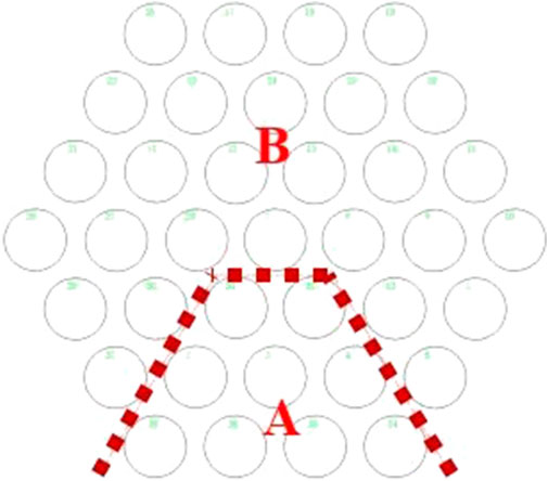
FIGURE 6. Schematic of the arrangement and number of heating rods.
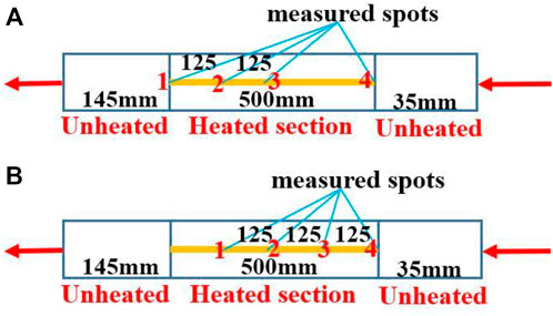
FIGURE 7. Schematic of the specific structure of measured spots of Type (A,B).
The temperature-measured spots of each heating rod are arranged as 1, 2, 3, and 4 in the order from top to bottom. Temperature measurement point 4 is taken as the height reference. It is clear that from the perspective of the entire rod bundle test section, there are five temperature measurement surfaces with relative heights of 0, 125, 250, 375, and 500 mm, respectively. Considering the arrangement of the two types of rods, it can be seen that there are 37 temperature measurement points at height 0, 28 temperature measurement points at height 125 mm, 37 temperature measurement points at height 250 mm, 37 temperature measurement points at height 375 mm, and 9 temperature measuring points at height 500 mm. In total, five groups of working conditions under different mass flow rates and heating power distributions are carried out by adjusting the control system. The conditions are summarized as follows in Table 4.
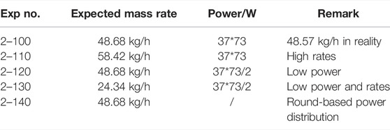
TABLE 4. Five groups of working conditions under different mass flow rates and heating power distributions.
To analyze the data of measured temperature, numerical simulations are required based on some usual flow models including the laminar model, SST k-w model, RSM model, and standard k-ε with an enhanced wall model.
To simplify the calculation, 1/12 of the heating section is simulated, as shown in Figure 8. The housing material is stainless steel. The heating surfaces are set to surface power heating conditions, i.e., 3443.4 W/m2. The outer wall is set to be adiabatic because the heat-insulating material is adopted around the surface in the test rig. The inlet is set to be mass-flow-inlet with 0.0011243 kg/s in rates.
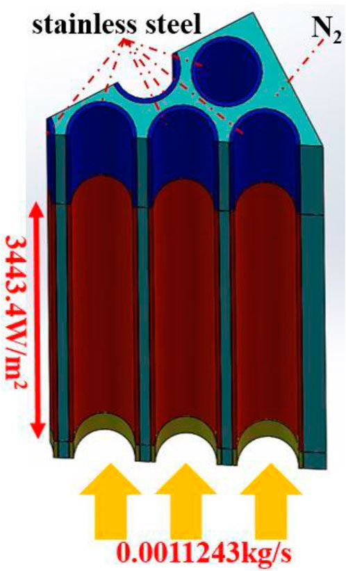
FIGURE 8. Schematic of the simulation model of the test section.
As for the experiment, according to the relative positions of the rods, the rod bundle of 37 rods is divided into six different types of characteristic rods, as shown in Figure 9A. The measured values corresponding to each characteristic rod at the same height are counted and averaged, to obtain the average temperature of the cladding of the characteristic rod at that exact height. Here, we should pay attention to eliminate unreasonable temperature measurement values.
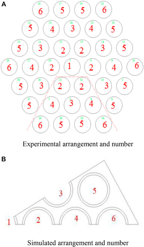
FIGURE 9. (A) Experimental arrangement and number. (B) Simulated arrangement and number.
As for the simulation, according to the thermal calculation results of 1 in 12 simulated parts, the area-weighted average temperature of the annular cladding surface of each rod at different heights is taken for reference, of which the arrangement and number are shown in Figure 9B.
Taking the 2–100 reference condition as an example, the temperature distributions of the six characteristic rods in the z-direction along the axial height are depicted from Figure 10A to Figure 10F. In these figures, the experimental values are marked as points, and the calculated simulation values under the four flow models are marked as lines.
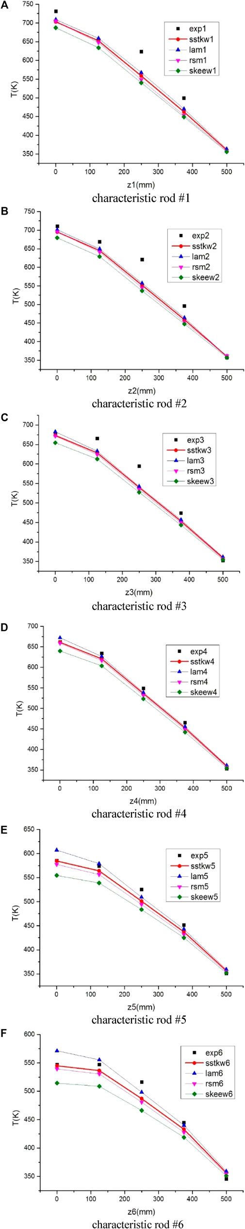
FIGURE 10. (Continued). Temperature distribution of the six characteristics rods along the axial height in the z-direction. (A) characteristic rod #1. (B) characteristic rod #2. (C) characteristic rod #3. (D) characteristic rod #4. (E) characteristic rod #5. (F) characteristic rod #6.
Considering the aforementioned six sets of data, the turbulence model SST k-w is relatively more consistent with the measured experimental data.
Applying this SST k-w turbulence model to all working conditions, it can be concluded that within the allowable error range, the simulated and experimental values are in good agreement.
Using the SST k-w turbulence model, it is achievable to simulate the heating section in a more elaborate way. Compared to Section 2, the gap structure, which lies between the fuel and the clad, the radial reflector and pressure vessel, and the radiation effects inside the reactor will all be considered in particular in this section.
As for the fuel layer, simulation models consist of rods, rod claddings, the gap between the rod and the cladding, the coolant, the radial reflector, and the pressure vessel, as shown in Figure 4B. In addition to the turbulence model, the DO radiation model is also considered and calculated due to the overall high-temperature environment.
The heating source item of the fuel is set at 6.19788e7W/m3. The vessel boundary is set to radiation, where the outer space temperature is 200 K and the emissivity is 0.5. In addition, relevant surfaces that participate in the radiation are all set at 0.5 in the value of emissivity. Specifically, the radiation inside the flow channel is considered including the radiation between the fuel rods and the claddings, the radiation among the claddings, and the radiation between the reflector and the claddings. Also, since the coolant helium is a monatomic gas, there is no need to consider gas radiation.
Details about the mesh are depicted in Figure 11. In order to find an appropriate mesh cell number and verify that the numerical results are not very sensitive to the mesh cell number, five cases with different mesh cell numbers are conducted. These cases have identical boundary conditions. The mesh cells and results for each case have been summarized in Table 5. According to the results, mesh 3 is chosen for further numerical calculation.
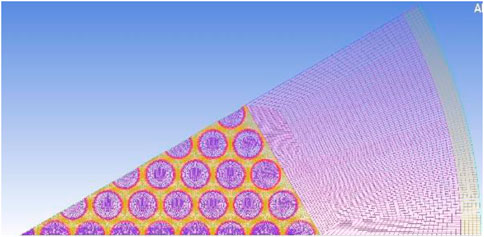
FIGURE 11. Schematic diagram of the detailed mesh.
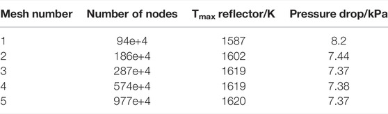
TABLE 5. Main calculation results of different meshes.
After grid independence check, the mesh with 2.87 million nodes is proved to be sufficient to satisfy the calculation requirement. The main calculation results are summarized in Table 6. Compared to the original results in Section 2, the maximum temperature of rods rises by 4%, and the inlet maximum pressure drop decreases by approximately 13%. It can be concluded that the gap structure, the radial reflectors and pressure vessel structure, and the radiation effects inside the reactor cannot be neglected.
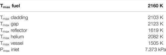
TABLE 6. Main calculation results.
According to the pressure contour and velocity vector, as shown in Figure 12 and Figure 13, helium flows into the open lattice structure and cools down the rods. The horizontal flow is relatively not obvious under this condition, leading to a horizontally uniform pressure distribution.

FIGURE 12. Pressure contour of helium.
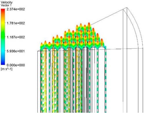
FIGURE 13. Velocity vector of helium.
As shown in Figure 14, due to the non-uniformity of radial heating, the coolant has the highest temperature in the outlet near the center-rod. In addition, the coolant temperature distribution is also the most uneven at this height.
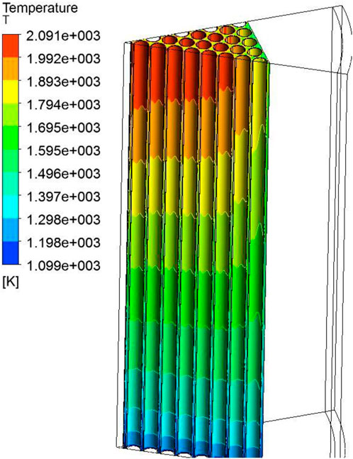
FIGURE 14. Temperature contour of helium.
Overall, this design displays an acceptable result in the temperature field, velocity field, and pressure field and is appropriate for matching the CCMHD system. However, the axial and radial power profile and more elaborate reactor structures are also required to obtain more solid results.
The study presents numerical simulations and experimental study on gas flow in an open lattice structure for the advanced space nuclear power system. The conclusions are summarized as follows:
1. Given a certain neutronics limitation, a dimension-optimized rod bundle channel can be raised quantitatively, which requires to balance the maximum rod temperature, the pressure drop, and other factors in the design.
2. The experiment reveals that the SST k-w turbulence model is appropriate for further simulation in the open lattice structure.
3. Considering the gap structure, which lies between the fuel and the clad, the radial reflector and pressure vessel, and the radiation effects inside the reactor, the maximum temperature of rods rises by 4%, and the inlet maximum pressure drop decreases by approximately 13%.
4. This design displays an acceptable result in the temperature field, velocity field, and pressure field and is appropriate for matching the CCMHD system. Further research is also required to take the axial and radial power profile and more elaborate structures in the whole reactor into considerations.
The original contributions presented in the study are included in the article/Supplementary Material. Further inquiries can be directed to the corresponding author.
ZW: conceptualization, data curation, formal analysis, investigation, methodology, validation, writing—original draft, and writing—review and editing; JZ: conceptualization (supporting); ZY: data curation (supporting); and LS: conceptualization (lead), funding acquisition (lead), methodology (lead), project administration (lead), resources (lead), software (lead), and supervision (lead).
This work performed in Tsinghua University was financially supported by the National S&T Major Project of China (Grant No. ZX06901).
The authors declare that the research was conducted in the absence of any commercial or financial relationships that could be construed as a potential conflict of interest.
All claims expressed in this article are solely those of the authors and do not necessarily represent those of their affiliated organizations, or those of the publisher, the editors, and the reviewers. Any product that may be evaluated in this article, or claim that may be made by its manufacturer, is not guaranteed or endorsed by the publisher.
An, W., Song, J., and Xie, J. (2015). Design of ultra-high temperature reactor core for magnetofluidic power generation [J]. Atomic Energy Sci. Technol. 49 (12), 5.
Harada, N., Le, C. K., and Hishikawa, M. (2006). in Basic Studies on Closed Cycle MHD Power Generation System for Space Application[C]//Aiaa Plasmadynamics and Lasers Conference.
Kobayashi, H., and Okuno, Y. (2000). Feasibility study on frozen inert gas plasma MHD generator. IEEE Trans. Plasma Sci. IEEE Nucl. Plasma Sci. Soc. 28 (4), 1296–1302. doi:10.1109/27.893319
Kugeler, K., and Zhang, Z. (2018). Modular high-temperature gas-cooled reactor power plant[M]. Springer.
Litchford, R. J., Bitteker, L. J., and Jones, J. E. (2001). Prospects for nuclear electric propulsion using closed-cycle magnetohydrodynamic energy conversion, NASA TP-2001-211274[R]. Washington D. C.: NASA.
Litchford, R. J., Bitteker, L. J., and Jones, J. E. (2001). Prospects for nuclear electric propulsion using closed-cycle magnetohydrodynamic energy conversion, NASA TP-2001-211274[R]. Washington D. C.: NASA.
Meng, T., Cheng, K., Zhao, F., Xia, C., and Tan, S. (2020). Computational flow and heat transfer design and analysis for 1/12 gas-cooled space nuclear reactor. Ann. Nucl. Energy 135, 106986. ISSN 0306-4549. doi:10.1016/j.anucene.2019.106986
Meng, T., Zhao, F., and Cheng, K. (2019). Numerical simulation of core flow and heat transfer in space gas cooled reactor [J]. Atomic Energy Sci. Technol. 053 (007), 1264–1271.
She, D., Xia, B., Guo, J., Wei, C-L., Zhang, , J., Li, F., et al. (2021). Prediction calculations for the first criticality of the HTR-PM using the PANGU code[J]. Nucl. Sci. Tech. 32 (9), 1–7. doi:10.1007/s41365-021-00936-5
Wang, Z., Sun, J., and Shi, L. Efficiency Analysis of Space Nuclear Reactor System Using Magnetic Fluid Power Generation [C]//The 16th National Academic Conference on Thermal Fluids for Reactors and the 2019 Academic Annual Conference of the Key Laboratory of Thermal and Hydraulic Technology for Nuclear Reactors in China. 2019 .
Wollman, M. J., and Zika (Apr, M. J. (2006). Prometheus project reactor module final report. United States. For Naval Reactors Information (SPP--67110-0008).
Keywords: gas-cooled reactor, dimension optimization, numerical simulation, thermal analysis, open lattice structure, space nuclear power system
Citation: Wang Z, Zhao J, Ye Z and Shi L (2022) Numerical Simulation and Experimental Study on Gas Flow in an Open Lattice Structure for an Advanced Space Nuclear Power System. Front. Energy Res. 10:939712. doi: 10.3389/fenrg.2022.939712
Received: 09 May 2022; Accepted: 02 June 2022;
Published: 28 September 2022.
Edited by:
Shichang Liu, North China Electric Power University, ChinaReviewed by:
Ming Ding, Harbin Engineering University, ChinaCopyright © 2022 Wang, Zhao, Ye and Shi. This is an open-access article distributed under the terms of the Creative Commons Attribution License (CC BY). The use, distribution or reproduction in other forums is permitted, provided the original author(s) and the copyright owner(s) are credited and that the original publication in this journal is cited, in accordance with accepted academic practice. No use, distribution or reproduction is permitted which does not comply with these terms.
*Correspondence: Lei Shi, c2hsaW5ldEB0c2luZ2h1YS5lZHUuY24=
Disclaimer: All claims expressed in this article are solely those of the authors and do not necessarily represent those of their affiliated organizations, or those of the publisher, the editors and the reviewers. Any product that may be evaluated in this article or claim that may be made by its manufacturer is not guaranteed or endorsed by the publisher.
Research integrity at Frontiers
Learn more about the work of our research integrity team to safeguard the quality of each article we publish.