
94% of researchers rate our articles as excellent or good
Learn more about the work of our research integrity team to safeguard the quality of each article we publish.
Find out more
ORIGINAL RESEARCH article
Front. Energy Res., 22 July 2022
Sec. Nuclear Energy
Volume 10 - 2022 | https://doi.org/10.3389/fenrg.2022.939499
This article is part of the Research TopicCFD Applications in Nuclear EngineeringView all 16 articles
In nuclear reactor safety research, the countercurrent gas-liquid two-phase flow in the hot leg of a pressurized water reactor (PWR) has attracted considerable attention. Previous work has proven that the algebraic interfacial area density (AIAD) model implemented in ANSYS CFX can effectively capture the gas-liquid interface and avoid the loss of information regarding the interfacial structure, which occurs after phase averaging in the Euler–Euler two-fluid approach. To verify the accuracy of the AIAD module implementation in ANSYS Fluent, the model based on the experimental data from the WENKA facility is validated in this work. The effects of the subgrid wave turbulence model, turbulence damping model, and droplet entrainment model are simultaneously investigated, which have been shown to be important in the previous work with CFX. The results show that the simulations are considerably and significantly deviate from the experiments when the turbulence damping is not considered. The free surface modeling of two-phase flow can be optimized by using the droplet entrainment model. The consistency between the simulation and experimental results is not enhanced after the subgrid wave turbulence model is adopted. Further investigations regarding the implementation of the subgrid wave turbulence model are necessary.
Multiphase flows are widely encountered in natural and industrial applications. In the nuclear reactor safety domain, the countercurrent gas-liquid two-phase flow in the hot leg of a pressurized water reactor (PWR) has been the focus of the research community for several decades. The behavior of countercurrent two-phase flows, which can be accurately predicted through three-dimensional (3D) computational fluid dynamics (CFD) codes, has critical implications for the safety and efficiency of the associated processes. CFD is widely used in many fields, such as evaluation of steam condensation heat transfer effects (Bian et al., 2018; Bian et al., 2019) and aerodynamic design of aircraft (Yang and Yang, 2012), etc., ANSYS Fluent is a commercial CFD software application that is highly universal and contains a variety of optimized physical models. In ANSYS Fluent, a broad range of mathematical models for multiphase phenomena is available, and the software can model complex geometries that are being increasingly used in both engineering practice and academic research (ANSYS Fluent, 2019). In horizontal gas-liquid two-phase flows, the key flow regimes pertain to smooth stratified flow, wavy flow, slug flow, and elongated bubbly flow. The different morphologies that occur under slug flow conditions are shown in Figure 1. Mandhane et al. (1974) and Taitel and Dukler (1976) introduced flow maps that can predict the transition between horizontal flow regimes in pipelines.

FIGURE 1. Different morphologies (Höhne and Mehlhoop, 2014).
With respect to turbulence three types of numerical simulation methods can be used to model free surface two-phase flows (Lakehal, 2002; Bestion, 2012): direct numerical simulation (DNS), large eddy simulation (LES), and the Reynolds average method (RANS). The Navier–Stokes equation can be solved directly using the DNS, the results of which involve all the spatial and temporal scales in turbulent two-phase flows. However, the computational cost of this method is extremely high, which limits its use in industrial applications. The computational costs associated with the LES are smaller; however, considerable resources may be consumed for large-scale and two-phase flows. The theoretical basis of the RANS technique is the Reynolds averaging concept, which represents a relatively effective and feasible solution to engineering problems. The principle of the Euler–Euler two-fluid method is to treat the phases as continuous media that penetrate each other (Porombka and Höhne, 2015). Due to the loss of information regarding the interfacial structure after phase averaging, the influence of the nonresolved small-scale structures of the interface on the mass, momentum, and heat transfer is ignored. Consequently, additional interphase forces must be introduced in the form of source terms to restore the gas-liquid interaction law in the Euler–Euler model.
To increase the accuracy of interfacial momentum transfer modelling under the Euler–Euler framework, it is necessary to select adequate force models, therein interphase drag is dominant. Several empirical correlations have been proposed for the estimation of drag coefficient, and their predictability is affected by various factors such as bubble size, aspect ratio, material properties as well contaminants. A generic model is still missing, especially in the case of complex flow conditions encountered in technical applications, where a hybrid model is often necessary (Tas-Koehler, et al., 2021). Researchers have proposed several techniques to ensure the applicability of their correlations under various hydrodynamics (Lockhart and Martinelli, 1949; Kim et al., 1985), for example, by including the particle Reynolds number, Eotvös number and Morton number as parameters (Ohnuki et al., 1988; Tomiyama et al., 1998). The parameter method based on empiricism is often limited by the form of the flow region, that is, a certain drag coefficient correlation is only suitable for a specific type of flow (Porombka, 2015). To overcome this limitation, Yao et al. (2005) and Coste (2013) proposed a local drag model to calculate the interfacial friction in two-phase flows involving large interfaces by estimating the position of the interface and applying a wall function on it. Moreover, Höhne and Vallée (2009), Höhne and Vallée (2010) presented the algebraic interfacial area density (AIAD) model, which enables the use of different models to calculate the drag force coefficient and interfacial area density for different flow patterns. In this method, an interfacial drag coefficient is directly calculated from the shear stress distribution at the stratified gas-liquid interface. The AIAD method has been successfully applied to simulating the countercurrent flow in the hot leg of a PWR (Höhne et al., 2011; Höhne et al., 2020).
Within the RANS Euler–Euler framework, the influence of turbulence must be modeled using a specific closure law. In terms of the introduction of two-equation turbulence models to the governing equation, Porombka and Höhne (2015) verified that the k–ω turbulence model was less sensitive to grid refinement and significantly enhanced the agreement with the experimental liquid levels. Moreover, the authors validated that near interface turbulence damping is indispensable for simulating the horizontal stratified flow. Another improvement is to consider the turbulent influence exerted by subgrid waves created by Kelvin–Helmholtz instabilities, which are smaller than the grid size. Höhne and Mehlhoop (2014) confirmed that the subgrid wave turbulence (SWT) model can enhance the processing capacity of the AIAD model for the physical process of the two-phase flow. In addition, Höhne and Hänsch (2015) previously proposed a new droplet entrainment model inside the AIAD framework to describe the droplet formation process. The simulation with the droplet entrainment model can reproduce the slug formation and propagation behavior observed in the experiment, and the model can be directly applied for industrial cases. The above developments have been implemented and tested in ANSYS CFX, while in the past years they were transferred to ANSYS Fluent. A comparative study of the model against experimental data and previous CFX studies is necessary for checking the implementation. This study focuses on modelling horizontally stratified two-phase flows in the hot leg of a PWR with the AIAD model in ANSYS Fluent.
This paper aims to provide additional levels of simulation support for the use of the AIAD method. The simulation results and experimental data for validation are derived from Porombka and Höhne (2015) and Höhne and Porombka (2018), whose studies were based on ANSYS and Stäbler et al. (2006) and Stäbler (2007), who conducted experiments at the WENKA facility, respectively.
The CFD simulation of free surface flows can be performed using the multi-fluid Euler–Euler modeling approach available in ANSYS Fluent. A detailed derivation of the governing equations can be found in Ishii and Mishima (1984). The continuity and momentum equations have the following form.
where
To obtain a closed equation system, a turbulence model must be supplemented for the determination of fluctuations. In this paper, the shear stress transport (SST) k–ω model is adopted to predict the turbulence parameters in a countercurrent free surface flow, which is less sensitive to grid refinement than the other two-equation turbulence models. Details regarding the model can be found in the work of Menter (1994).
The AIAD model has been depicted by previous researchers, so a brief description is given here. According to the flow condition, three regime forms—namely, bubbly flow, droplet flow, and free surface flow can be present in the domain. The AIAD approach identifies the local flow form firstly and selects suitable models to calculate the drag coefficient and the interfacial area density. Blending functions based on the volume fraction for droplets, bubbles, and free surface morphologies (fD, fB, and fFS) are used to realize the switch between the models. They are defined as
where
The drag force FD is the shear force generated at the phase interface due to the relative velocity between the gas and liquid, which is affected by the contact area, fluid density, and other factors. In this paper, the classical AIAD model is used to model the drag force of a gas-liquid two-phase flow:
where A is the interfacial area density, CD is the drag force coefficient, and U is the relative velocity of the two phases. When the local flow field is a droplet flow or a bubble flow,
The bubbles and droplets in the AIAD approach are regarded as regular spheres with a constant diameter, represented as dB and dD, respectively. The interfacial area density AD for the droplet flow is calculated as
where
where AB is the interfacial area density of the bubbly flow.
The interfacial area density of the free interfacial flow, AFS, is defined as the magnitude of the volume fraction gradient of the liquid phase, and n is the normal vector of the free surface.
The local interfacial area density A is calculated as the sum of AFS, AB, and AD, weighted by the blending functions fFS, fB, and fD.
In the Euler multiphase flow framework, the velocity and turbulence for each phase are described by separate sets of equations. A velocity difference exists between the different phases in the fluids. And the drag force coefficient CD is calculated as
In the range of medium and high Reynolds numbers, the interfacial drag force coefficient of the droplet flow and bubbly flow CD,D/B can be approximated with a constant value of 0.44. For free surface flow, Höhne and Mehlhoop (2014) assumed that the effect of the drag force on both sides of the phase interface was similar to the wall shear force and served to reduce the countercurrent velocity difference between the gas-liquid two phases. In AIAD model, the following formula is used:
where
The small wave created by Kelvin–Helmholtz instabilities that are smaller than the grid size is neglected in traditional two-phase flow CFD simulations; however, the influence of these waves on the turbulence kinetic energy of the liquid side in free surface flow can be significantly large. The interfacial stability of two-phase flow is the result of the interaction of gravity and surface tension. Brocchini and Peregrine, (2001) described a wide range of free surface behavior when turbulence occurs at the interface. The surface behavior depends on two dimensionless numbers, namely, the Weber number (
where
where qu and ql represent the lower and upper bounds of a surface that is no longer smooth and finally disintegrates due to turbulence. They are defined as
where L is a typical length scale of the dominant interface features and gn is the scalar product of the interface normal and gravity. Finally, the source term Pk,SWT is added to the turbulent kinetic energy equations, which are blended only in the vicinity of the free surface by using the blending function.
In a horizontal two-phase flow, where droplets, bubbles and free surface co-exist (see Figure 1), the entrainment rate is a key parameter that changes the flow characteristics. Under the high gas velocity conditions, the shear stress leads to the deformation of the interface. The interfacial waves generated by the Kelvin–Helmholtz instability are converted into dispersed droplets carried by the gas phase, and the number of droplets increases with the motion of the disturbance waves. Consequently, a portion of the wave disintegrates into several droplets. The breakage depends on the surrounding flow pattern and shape of the interface. Höhne and Hänsch (2015) constructed a droplet entrainment model (DEM) for horizontal segregated flows in the AIAD framework. The new droplet phase has the material properties of the liquid phase, the velocity of which is generally consistent with the gas phase. Considering the DEM, the free surface modeling of the two-phase flow can be optimized.
In free surface flows, a high-velocity gradient exists at the interface between two fluids, which generates high turbulence in both phases. Turbulence damping is needed to be considered for correct modelling of such flows. Thompson and Sawko (2012) investigated the influence of the additional turbulence damping in the interfacial region. Egorov et al. (2004) proposed an asymmetric dampening function within the Euler–Euler framework, in which an extra source term SD was added to the right-hand side of the ω-equation in both liquid and gas phases:
where
The experimental data of the horizontally stratified two-phase flow for validation of the models are obtained from the WENKA facility, as reported by Stäbler et al. (2006), Stäbler (2007). The data correspond to a simplified model of hot leg injection in a PWR, as shown in Figure 3. Water enters from the left side of the rectangular pipe, while air enters from the right side of the pipe, and a splitter plate exists to adjust the liquid level height at the left entrance.
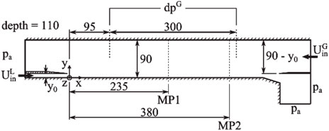
FIGURE 3. Cross-section of the WENKA test section, from Porombka and Höhne (2015).
ANSYS Fluent 2019R3 is used to perform the two-phase flow simulation, and the AIAD model is implemented for the first time in the form of a beta function. The flow parameters in the experiment are as specified in Table 1, and two measurement positions MP1 and MP2 are considered.
The inlet boundary conditions are assumed to be a fully developed turbulent channel flow at the air inlet, and a turbulent plane channel flow is assumed at the liquid inlet. The profile that is rescaled and normalized at the gas inlet is derived from the work of Melling and Whitelaw (1976), and a 1/7 power law profile is implemented at the liquid inlet, as indicated by Wilcox (1995). Furthermore, the supercritical flow condition is adopted considering the dimensionless number
In addition, both the gas and liquid outlets are connected to the external environment involving a constant atmospheric pressure of 0.101,325 MPa. The wall and plates are treated as no-slip boundaries, which indicates that the velocity of the fluid at the wall (or relative velocity) is zero. The meshing of the 3D computational domain is performed using the commercial grid generation software ICEM CFD, which consists of
The pseudo transient solver is adopted in Fluent in the context of the AIAD; this method adjusts the implicit “under relaxation” of the stationary flow through a physical pseudo time step. The achievement of steady-state flow is determined not only by the residuals but also by the balance of the mass flows at the inlets and outlets. The acceptable difference is 1–3% of the inlet mass flow. This criterion is reached after 250,000 iterations in all runs. The other parameters and numerical discretization methods used in Fluent are shown in Supplementary Appendix Tables SA1,SA2 in the appendix.
Within the scope of the work, four numerical runs are compared based on the experimental data, which consider fully or partly the effects of droplet entrainment, turbulence damping and subgrid wave turbulence discussed above. An overview of the four run configurations is given in Table 2.
Meshing is an integral part of CFD simulations, which directly influences the simulation results. To avoid the influence of the mesh on the results, four mesh resolutions are compared for Run 4. The four meshes are labeled “Mesh 1,” “Mesh 2,” ‘‘Mesh 3,’’ and “Mesh 4,” and the associated parameters are shown in Supplementary Appendix Table SA3 (see the appendix). The sensitivity of the grid is verified by comparing the following variables: the measured mean wave amplitude yd at MP1 and MP2, velocities u, turbulence kinetic energy k, and Reynolds stress components
Figure 5 shows that phase velocities obtained with the coarse meshes, i.e. Mesh 1 and Mesh 2, deviate slightly from those with Mesh 3 and Mesh 4. The deviation decreases from MP1 to MP2. Additional information on the liquid levels is provided in Supplementary Appendix Table SA4 (see the appendix), which shows little deviation under the four investigated grid resolutions.
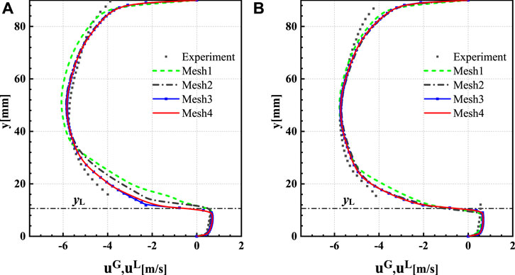
FIGURE 5. Comparison of the x-velocity at MP1 and MP2 for the four meshes, (A) the distribution of the x-velocity at MP1, (B) the distribution of the x-velocity at MP2.
The main differences pertain to the turbulent kinetic energy and Reynolds stress component. As can be seen from Figure 6, due to high gradients the region close to the gas-liquid interface is sensitive to mesh refinement. On the gas-phase side, both the turbulent kinetic energy and Reynolds stress are apt to be over-estimated by the coarse mesh. While on the liquid-phase side the turbulent kinetic energy increases with mesh resolution, no consistent trend is observed for the Reynolds stress component. Overall, the result of Mesh 3 is in agreement with that of Mesh 4. Considering the accuracy of the simulation results and finiteness of the computing resources, Mesh 3 is selected to perform the subsequent calculations.
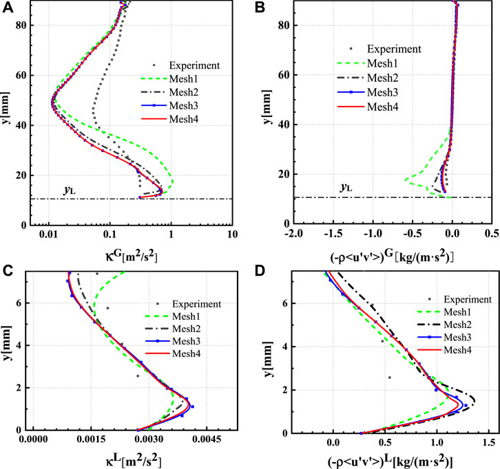
FIGURE 6. Turbulent kinetic energy (κ) and Reynolds stress component (-ρ<u'v'>) for four meshes at MP1, (A) turbulent kinetic energy distribution of the gas phase, (B) Reynolds stress component distribution of the gas phase, (C) turbulent kinetic energy distribution of the liquid phase, (D) Reynolds stress component distribution of the liquid phase.
In the experiment, only bulk quantities were specified at the inlets. Therefore, the velocity profiles were assumed according to previous studies. Porombka and Höhne (2015) considered a fully developed turbulent channel flow as a reasonable assumption for the gas inlet and plane turbulent channel flow for the liquid inlet. This condition is referred to as “inlet condition 1”. In this work, another inlet condition referred to as “inlet condition 2” is applied to investigate the influence of inlet boundary conditions in the AIAD model. This condition contains the velocity and turbulence profile obtained by extending the gas and liquid inlet piping in a precursor simulation. The gas and liquid inlets extend by 3,000 and 500 mm, respectively, and the velocity profiles obtained in this way are shown in Figure 7.
No significant difference exists between the two conditions in terms of the velocity profile and gas-phase turbulence parameters, see Figure 8, Figures 9A,B. However, in terms of the turbulence parameter profile on the liquid side, the results under inlet condition 1 are closer to the experimental value, see Figures 9C,D. Therefore, to the best of our knowledge, the assumption of the entry conditions introduced by Porombka and Höhne (2015) is reasonable. Nonetheless, regardless of the two inlet conditions, the simulation results show no complete approximation of the experimental results. Further validation for more suitable entry conditions must be performed in future work.
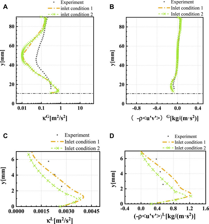
FIGURE 9. Turbulent kinetic energy (κ) and Reynolds stress component (-ρ<u'v'>) at MP1 under different inlet conditions, (A) turbulent kinetic energy distribution of the gas phase, (B) Reynolds stress component distribution of the gas phase, (C) turbulent kinetic energy distribution of the liquid phase, (D) Reynolds stress component distribution of the liquid phase.
To investigate the effect of the DEM, SWT model, and turbulence damping model, four runs, as shown in Table 2, are compared. The profiles of gas volume fraction at MP1 and MP2 are shown in Figure 10. The gas-liquid interface is identified at
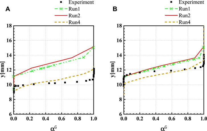
FIGURE 10. Gas volume fraction, (A) gas volume fraction distribution at MP1 and (B) gas volume fraction distribution at MP2.
The significance of the turbulence damping in modelling the horizontal two-phase stratified flow simulation has been verified and validated by Porombka and Höhne (2015). The authors found that the water level is larger than that in the experiment and decreases in the mean flow direction when the turbulence dampening term is neglected. These findings are confirmed by the simulation results of Run 3 based on Fluent in this work. The deactivation of the turbulence damping leads to a partial reversal of the flow and fluctuation of the liquid level, as depicted in Figure 11B). In addition to yielding a qualitatively different velocity profile, the turbulence kinetic energy and Reynolds stress are overpredicted in Run 3 compared with the measured values. Excessive turbulence is produced in the gas-liquid interface region due to the increase in the interfacial shear when the turbulence damping model is not applied. The gas volume fraction, turbulence kinetic energy, and Reynolds stress in the liquid phase predicted in Run 3 are not shown as they are considerably greater than the measured values. This aspect highlights the importance of the turbulence damping model in the AIAD framework.
The flow regimes change from a wavy flow to a lamellar flow when the SWT model is not considered in Run 4, as depicted in Figure 11C). Generally, the deviation between the simulation results and measured profile decreases when the SWT model is not applied. Run 4 exhibits the highest agreement with the experimental liquid levels. This finding contradicts the CFX simulation results obtained by Höhne and Porombka (2018), who noted that introducing additional liquid-side turbulence production due to the SWT mechanism does not significantly influence the liquid levels.
The horizontal and vertical velocity profiles of the gas and liquid phases are depicted in Figure 12 along with the measured profiles. The velocity profile in Run 2 is nearly identical to that in Run 1, indicating that the DEM does not considerably influence the velocity in the horizontal stratified flow model. Run 4 yields an x-velocity profile that is qualitatively similar to the experimentally obtained one. When the SWT model is not applied, the y-velocity profile matches the experimental values. In addition, compared to the turbulence damping model, the effect of the SWT model is less notable when modeling a two-phase stratified flow. The SWT source term is added to the k transport equation of the liquid phase. The SWT model, directly and indirectly affects the turbulence parameters on the liquid and gas sides. In the center of the upper airflow zone of the square pipe, the curves of the turbulent kinetic energy are nearly identical, although the values are underestimated compared to the measured values, as shown in Figure 13A). When the SWT source term is neglected, the overprediction of the turbulent kinetic energy in the interface region is reduced. Moreover, the SWT model exhibits a notable effect, which can be observed in terms of the Reynolds stress components at MP1, see Figure 13B) and Figure 13D). While increasing both gas and liquid turbulent kinetic energy at the interface, including SWT decreases and increases the Reynolds stress on the gas and liquid side, respectively. Since no further configuration options exist for the SWT model in Fluent, the correctness of the model implementation requires further verification.
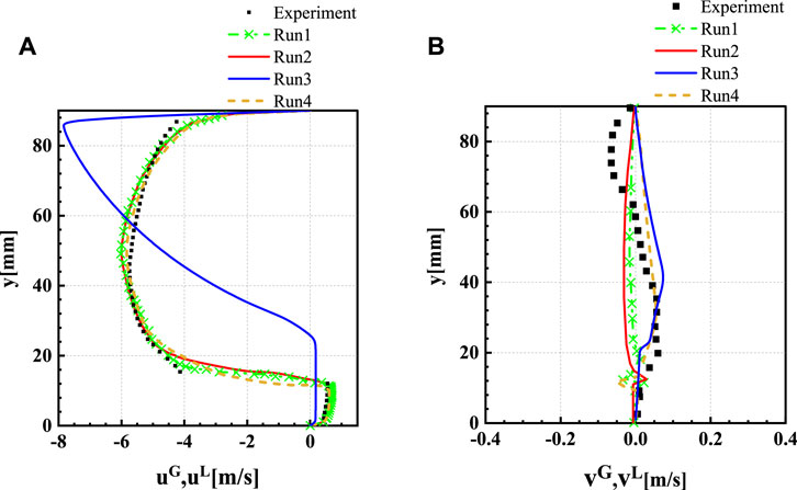
FIGURE 12. Velocity component at MP1, (A) the distribution of x-velocity, (B) the distribution of y-velocity.
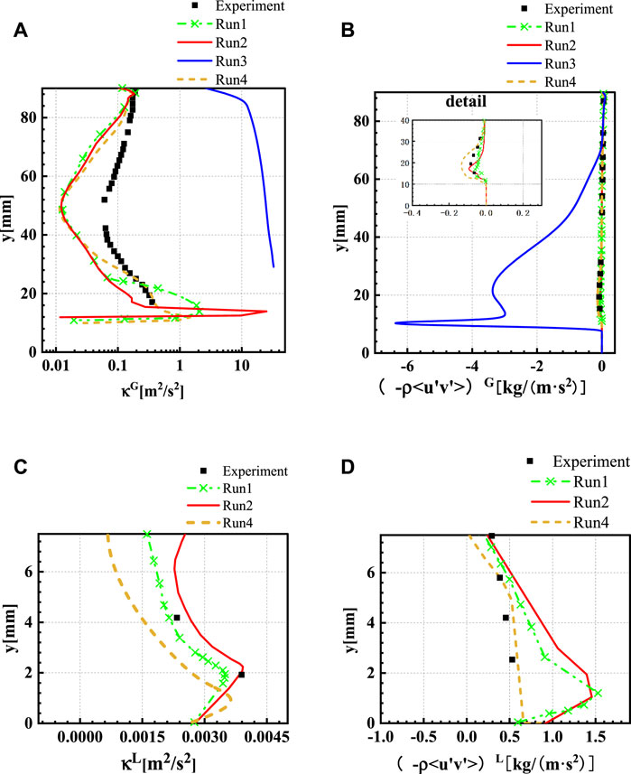
FIGURE 13. Turbulent kinetic energy (κ) and Reynolds stress component (-ρ<u'v'>) at MP1, (A) turbulent kinetic energy distribution of the gas phase, (B) Reynolds stress component distribution of the gas phase, (C) turbulent kinetic energy distribution of the liquid phase, (D) Reynolds stress component distribution of the liquid phase.
Additionally, except for the turbulent kinetic energy at the gas-liquid interface, other quantities are qualitatively indistinguishable whether the DEM is considered or not. When the entrainment of the droplets at the gas-liquid interface is ignored, the turbulent kinetic energy at the interface increases sharply, and the deviation from the experiment results increases for the gas phase. In summary, the free surface modeling of two-phase flow can be optimized using the DEM. Due to the small amount of droplet entrainment in this case, the absence of this model does not considerably influence the results. Further validation is desirable for the cases where droplet entrainment plays an important role.
The accuracy of the AIAD module implementation in ANSYS Fluent is investigated based on the experimental data from the WENKA facility, and the following conclusions are obtained:
1) The existing inlet assumptions regarding the fully developed and plane turbulent channel flows were verified to be reasonable and appropriate for the simulation.
2) The simulation results are critically distorted and deviate significantly from the experimental results when the effect of turbulence damping is not considered. The absence of turbulence damping results in the instability of the simulation.
3) The accuracy of the AIAD model at the phase interface is enhanced after the entrained phase is considered. However, the enhancement effect of the DEM for depicting the interface is not significant since only a few droplets are entrained in the WENKA two-phase flow experiment.
4) The effect of the SWT generated by Kelvin–Helmholtz instabilities is not yet clear. The consistency between the simulation results obtained using Fluent and experimental results is not enhanced after the SWT model is adopted. Further validation in terms of the SWT of higher We and Fr regimes should be performed in future work. Furthermore, the conclusion regarding the effect of the SWT model is inconsistent with that found in the previous studies with ANSYS CFX.
The raw data supporting the conclusion of this article will be made available by the authors, without undue reservation.
HY and LL contributed to the conception and design of the study. HZ performed the numerical simulation. LL and HZ wrote the first draft of the manuscript. YL wrote sections of the manuscript. All authors contributed to manuscript revision, read, and approved the submitted version.
This work was supported by the National Natural Science Foundation of China (Grant No. 51906262) and Natural Science Foundation of Hunan Province, China (Grant No. 2020JJ5735).
The computational resource at the High-Performance Computing Center of Central South University is also gratefully acknowledged.
The authors declare that the research was conducted in the absence of any commercial or financial relationships that could be construed as a potential conflict of interest.
All claims expressed in this article are solely those of the authors and do not necessarily represent those of their affiliated organizations, or those of the publisher, the editors and the reviewers. Any product that may be evaluated in this article, or claim that may be made by its manufacturer, is not guaranteed or endorsed by the publisher.
The Supplementary Material for this article can be found online at: https://www.frontiersin.org/articles/10.3389/fenrg.2022.939499/full#supplementary-material
Bestion, D. (2012). Applicability of two-phase CFD to nuclear reactor thermalhydraulics and elaboration of Best Practice Guidelines. Nucl. Eng. Des. 253, 311–321. doi:10.1016/j.nucengdes.2011.08.068
Bian, H., Sun, Z., Cheng, X., Zhang, N., Meng, Z., Ding, M., et al. (2018). CFD evaluations on bundle effects for steam condensation in the presence of air under natural convection conditions. Int. Commun. Heat Mass Transf. 98, 200–208. doi:10.1016/j.icheatmasstransfer.2018.09.003
Bian, H., Sun, Z., Zhang, N., Meng, Z., and Ding, M. (2019). A new modified diffusion boundary layer steam condensation model in the presence of air under natural convection conditions. Int. J. Therm. Sci. 145, 105948. doi:10.1016/j.ijthermalsci.2019.05.004
Brocchini, M., and Peregrine, D. (2001). The dynamics of strong turbulence at free surfaces. Part 1. Description. J. Fluid Mech. 449, 225–254. doi:10.1017/S0022112001006012
Coste, P. (2013). A large interface model for two-phase CFD. Nucl. Eng. Des. 255, 38–50. doi:10.1016/j.nucengdes.2012.10.008
Egorov, Y., Boucker, M., Martin, A., Pigny, S., Scheuerer, M., and Willemsen, S. (2004). Validation of CFD codes with PTS-relevant test cases. 5th Euratom Framework Programme ECORA Project, 91–116.
Höhne, T.Deendarlianto, and Lucas, D. (2011). Numerical simulations of counter-current two-phase flow experiments in a PWR hot leg model using an interfacial area density model. Int. J. Heat Fluid Flow 32 (5), 1047–1056. doi:10.1016/j.ijheatfluidflow.2011.05.007
Höhne, T., and Hänsch, S. (2015). A droplet entrainment model for horizontal segregated flows. Nucl. Eng. Des. 286, 18–26. doi:10.1016/j.nucengdes.2015.01.013
Höhne, T., and Mehlhoop, J.-P. (2014). Validation of closure models for interfacial drag and turbulence in numerical simulations of horizontal stratified gas–liquid flows. Int. J. Multiph. Flow 62, 1–16. doi:10.1016/j.ijmultiphaseflow.2014.01.012
Höhne, T., and Porombka, P. (2018). Modelling horizontal two-phase flows using generalized models. Ann. Nucl. Energy 111, 311–316. doi:10.1016/j.anucene.2017.09.018
Höhne, T., Porombka, P., and Moya, S. (2020). Validation of AIAD sub-models for advanced numerical modelling of horizontal two-phase flows. Fluids 5, 102. doi:10.3390/fluids5030102
Höhne, T., and Vallée, C. (2010). Experiments and numerical simulations of horizontal two-phase flow regimes using an interfacial area density model. J. Comput. Multiph. Flows 2, 131–143. doi:10.1260/1757-482X.2.3.131
Höhne, T., and Vallée, C. (2009). Modelling of stratified two phase flows using an interfacial area density model. WIT Trans. Eng. Sci. 63, 123–133. doi:10.2495/MPF090111
Ishii, M., and Mishima, K. (1984). Two-fluid model and hydrodynamic constitutive relations. Nucl. Eng. Des. 82 (2), 107–126. doi:10.1016/0029-5493(84)90207-3
Kim, H. J., Lee, S. C., and Bankoff, S. G. (1985). Heat transfer and interfacial drag in countercurrent steam-water stratified flow. Int. J. Multiph. Flow 11 (5), 593–606. doi:10.1016/0301-9322(85)90081-3
Lakehal, D. (2002). On the modelling of multiphase turbulent flows for environmental and hydrodynamic applications. Int. J. Multiph. Flow 28 (5), 823–863. doi:10.1016/S0301-9322(01)00086-6
Lockhart, R. W., and Martinelli, R. C. (1949). Proposed correlation of data for isothermal two-phase, two-component flow in pipes. Chem. Eng. Prog. 45 (1), 39–48.
Mandhane, J. M., Gregory, G. A., and Aziz, K. (1974). A flow pattern map for gas—Liquid flow in horizontal pipes. Int. J. Multiph. Flow 1 (4), 537–553. doi:10.1016/0301-9322(74)90006-8
Melling, A., and Whitelaw, J. H. (1976). Turbulent flow in a rectangular duct. J. Fluid Mech. 78 (2), 289–315. doi:10.1017/S0022112076002450
Menter, F. R. (1994). Menter, F.: Two-equation eddy-viscosity transport turbulence model for engineering applications. AIAA J. 3232 (88), 1598–1605. doi:10.2514/3.12149
Ohnuki, A., Adachi, H., and Murao, Y. (1988). Scale effects on countercurrent gas-liquid flow in a horizontal tube connected to an inclined riser. Nucl. Eng. Des. 107 (3), 283–294. doi:10.1016/0029-5493(88)90036-2
Porombka, P., and Höhne, T. (2015). Drag and turbulence modelling for free surface flows within the two-fluid Euler–Euler framework. Chem. Eng. Sci. 134, 348–359. doi:10.1016/j.ces.2015.05.029
Porombka, P. (2015). “Modelling of free surface flow within the two-fluid Euler-Euler Framework,” in ASME/JSME/KSME 2015 Joint Fluids Engineering Conference. Seoul, South Korea: American Society of Mechanical Engineers.doi:10.1115/AJKFluids2015-05133
Stäbler, T. (2007). Experimentelle Untersuchung und physikalische Beschreibung der Schichtenströmung in horizontalen Kanälen. Stuttgart, Germany: Universität Stuttgart. (PhD Thesis). doi:10.5445/IR/200068452
Stäbler, T., Meyer, L., Schulenberg, T., and Laurien, E. (2006). “Turbulence structures in horizontal two-phase flows under counter-current conditions,” in Fluids engineering summer meeting (Berlin, Germany: Stuttgart), 61–66. doi:10.1115/FEDSM2006-98211
Taitel, Y., and Dukler, A. E. (1976). A model for predicting flow regime transitions in horizontal and near horizontal gas-liquid flow. AIChE J. 22 (1), 47–55. doi:10.1002/aic.690220105
Tas-Koehler, S., Liao, Y., and Hampel, U. (2021). A critical analysis of drag force modelling for disperse gas-liquid flow in a pipe with an obstacle. Chem. Eng. Sci. 246, 117007. doi:10.1016/j.ces.2021.117007
Thompson, C. P., and Sawko, R. (2012). “Interface turbulence treatments in RANS model of stratified gas/liquid flows,” in Proceedings of the ASME 2012 international mechanical engineering congress and exposition. Houston, Texas, United States: ASME, 621–626. doi:10.1115/IMECE2012-89421
Tomiyama, A., Kataoka, I., Zun, I., and Sakaguchi, T. (1998). Drag coefficients of single bubbles under normal and micro gravity conditions. JSME Int. J. Ser. B Fluids. Therm. Eng. 41 (2), 472–479. doi:10.1299/jsmeb.41.472
Wilcox, D. C. (1995). Turbulence modeling for CFD. DCW Ind. 289, 406–407. doi:10.1017/S0022112095211388
Yang, W., and Yang, Z. (2012). Aerodynamic investigation on tiltable endplate for WIG craft. Aircr. Eng. Aerosp. Technol. 84, 4–12. doi:10.1108/00022661211194933
Yao, W., Bestion, D., Coste, P., and Boucker, M. (2005). A three-dimensional two-fluid modeling of stratified flow with condensation for pressurized thermal shock investigations. Nucl. Technol. 152, 129–142. doi:10.13182/NT05-A3665
A interfacial area density (1/m)
d diameter (m)
g gravitational acceleration (m/s2)
L length (m) liquid
n unity normal vector
p production term [kg/(m s3)]
t time (s)
u,v,w Cartesian velocity components (m/s)
x,y,z Cartesian coordinates (m)
y0 liquid level at inlet (m)
yL liquid level (m)
Fr Froude number (−)
Re Reynolds number (−)
We Weber number (−)
ρ density (kg/m3)
σ surface tension (N/m)
B bubble
D droplet
FS free surface
G gas
i,j,k tensor indices
k phase index
L length (m) liquid
sw subgrid waves
SWT subgrid wave turbulence
T turbulent quantity
Keywords: thermal hydraulics, two-phase flow, AIAD, CFD, subgrid wave turbulence, droplet entrainment, turbulence damping
Citation: Yan H, Zhang H, Höhne T, Liao Y, Lucas D and Liu L (2022) Numerical modeling of horizontal stratified two-phase flows using the AIAD model. Front. Energy Res. 10:939499. doi: 10.3389/fenrg.2022.939499
Received: 09 May 2022; Accepted: 27 June 2022;
Published: 22 July 2022.
Edited by:
Zhaoming Meng, Harbin Engineering University, ChinaReviewed by:
Haozhi Bian, Harbin Engineering University, ChinaCopyright © 2022 Yan, Zhang, Höhne, Liao, Lucas and Liu. This is an open-access article distributed under the terms of the Creative Commons Attribution License (CC BY). The use, distribution or reproduction in other forums is permitted, provided the original author(s) and the copyright owner(s) are credited and that the original publication in this journal is cited, in accordance with accepted academic practice. No use, distribution or reproduction is permitted which does not comply with these terms.
*Correspondence: Liu Liu, bC5saXVAY3N1LmVkdS5jbg==
Disclaimer: All claims expressed in this article are solely those of the authors and do not necessarily represent those of their affiliated organizations, or those of the publisher, the editors and the reviewers. Any product that may be evaluated in this article or claim that may be made by its manufacturer is not guaranteed or endorsed by the publisher.
Research integrity at Frontiers

Learn more about the work of our research integrity team to safeguard the quality of each article we publish.