 Chunxu Li1
 Xinrui Liu
 Rui Wang
 Li Zhang
95% of researchers rate our articles as excellent or good
Learn more about the work of our research integrity team to safeguard the quality of each article we publish.
Find out more
ORIGINAL RESEARCH article
Front. Energy Res. , 22 July 2022
Sec. Smart Grids
Volume 10 - 2022 | https://doi.org/10.3389/fenrg.2022.939376
This article is part of the Research Topic Applications of Data-Driven Artificial Intelligence in Integrated Energy Systems View all 10 articles
Although the stability of the grid-connected photovoltaics (PV) and energy storage systems under weak grids has been widely researched, the classical improvement methods focus more on suppressing the harmonics introduced by the phase-locked loop (PLL). Furthermore, the current distortion caused by the DC voltage loop is difficult to be eliminated. In this study, based on the hybrid energy storage system of battery-supercapacitor, a dual-loop compensation method is proposed. First, the small-signal model and output impedance matrix are built in d-q axis. Second, for different disturbance loops, a DC voltage loop disturbance compensation method based on power feedforward is proposed to suppress the harmonics caused by the DC voltage controller (DVC). In addition, a voltage feedforward PLL disturbance compensation method is proposed, which can reduce the PLL perturbations and revise the output impedance to improve system stability. Finally, the output impedance frequency characteristic analysis and the hardware-in-the-loop (HIL) simulation results show that the proposed control method can effectively improve the stability of the system under weak grids.
Renewable energy sources such as PV have the characteristics of intermittency and randomness. In order to ensure the stability of the microgrid system, certain capacity energy storage devices need to be configured in the microgrid system. The battery-supercapacitor (SC)–based hybrid energy storage system (HESS) has been proposed to mitigate the impact of dynamic power exchanges on the battery’s lifespan (Jing et al., 2017). Aiming at the control of the PV and energy storage microgrid, (Akram et al., 2018), proposed an iterative search algorithm to improve the optimal size of the PV and energy storage systems in the microgrid. (Tricarico et al., 2020) made improvements on the microgrid topology. In (Xu and Cen, 2021), a coordinated control strategy was used to suppress the power fluctuations of grid-connected PV power generation systems. Due to the interaction between the inverter and grid impedance, will cause a decrease in system stability. Therefore, considering the weak grid conditions, the research on stable control of grid-connected inverters is particularly important.
The impedance analysis is widely used in the stability analysis of grid-connected inverters. (Sun, 2011) pointed out that if the ratio of the grid impedance to the inverter output impedance satisfies the Nyquist stability criterion, the system will remain stable. (Wen et al., 2014) analyzed the control of the voltage controller in the low-frequency range, the output impedance decreases as the voltage loop bandwidth increases, and the wider will be the frequency range of the negative impedance. In this regard, (Xu et al., 2017), proposed an adaptive control method, which adjusts the voltage feedforward signal through an adaptive criterion to improve the stability. (Lu et al., 2018) revealed that the dc-link voltage control may cause high-frequency oscillations in the inverter. (Yuan et al., 2017) pointed out that controller parameters of DVC affect the oscillation. In addition, (Harnefors et al., 2015), suggested not to select the bandwidths of DVC, unnecessarily large, to avoid oscillation. (Dong et al., 2014); (Wen et al., 2015a); (Wen et al., 2015b); (Bakhshizadeh et al., 2016); (Yang et al., 2019); (Nicolini et al., 2020) mainly analyzed the influence of the PLL on the stability of the inverter and pointed out that the PLL is one of the main factors that affect the stability of the system. The method of introducing a feedforward function was used by (Wang et al., 2010); (Xue et al., 2012); (Zhang et al., 2018) to improve stability.
To solve the influence of PLL on system stability, (Cespedes and Sun, 2014); (Yang et al., 2014); (Zhou et al., 2014); (Davari and Mohamed, 2016) made different attempts. In (Zhou et al., 2014), a small-signal model of the control system including the PLL was established. It was discussed that the gain of the PLL has a greater effect on the stability of the inverter, and a method is proposed to reduce the bandwidth of the PLL to solve this problem. (Yang et al., 2014) used virtual impedance to regulate the output impedance instead of adjusting the current loop gain to improve the inverter’s harmonic suppression and stability robustness. The current control loop can be independently designed. (Wang et al., 2014) reviewed the control methods of VSCs and CSCs based on virtual impedance. (Cao et al., 2017) proposed an impedance matrix modeling method, which simplifies the stability judgment process. However, the impact of the DC side voltage fluctuation is ignored. For PV grid-connected systems, the DC side voltage will fluctuate under the influence of factors such as intensity of light. Therefore, it is necessary to take DC voltage fluctuations into consideration.
This study aims at the stability of weak grid-connected PV and energy storage systems. To meet the dynamic response requirements, a HESS is adopted. For the grid-connected inverter, the small-signal analysis and impedance method are used to analyze the stability of the system, including the influence of the PLL and the voltage loop controller. The main contributions are as follows:
1) Considering the State of Charge (SoC) of the battery, an adaptive bandwidth frequency low-pass filter (LPF) is proposed, smoothing the low-frequency power from the battery, ensuring DC bus voltage stability.
2) A DC voltage loop disturbance compensation control based on power feedforward is added to the DVC to reduce the perturbation signals caused by the controller parameters.
3) To eliminate the negative effects introduced by PLL, a disturbance compensation method based on voltage feedforward is proposed, which further improves the stability of grid connections.
The rest of this article is organized as follows. Section 3 establishes the impedance model of the grid-connected inverter. Section 4 discusses the proposed control method and analyzes the control effect. Section 5 builds a HIL platform to verify that the proposed method can reduce the frequency range of the negative impedance characteristics. The conclusion is given in Section 6.
Figure 1 is a weak grid-connected PV and energy system. PV and HESS are connected to the DC bus through DC/DC converters. Therefore, the DC bus voltage becomes a key indicator for stable operation.
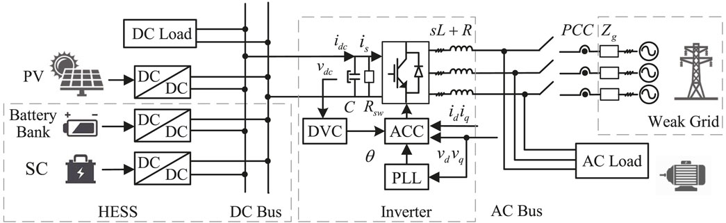
FIGURE 1. Grid-connected PV and energy storage system.
The PV array is connected to the DC microgrid through a boost converter, which adopts the MPPT control algorithm. The HESS uses a bidirectional DC/DC converter to connect to the DC microgrid. Due to the imbalance between power generation and load demand, the HESS is proposed to maintain the DC bus voltage
In Figure 2,
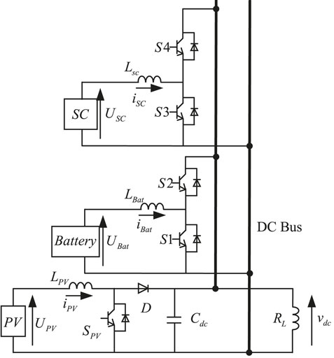
FIGURE 2. DC microgrid structure.
The control block diagram of the voltage stabilization control strategy is shown in Figure 3. The basic idea of this control strategy is that the battery supports the low-frequency part of power changes and the SC supports the high-frequency part of power changes. Therefore,
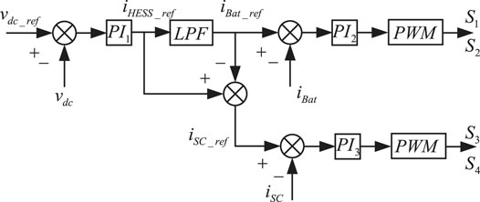
FIGURE 3. Structure of voltage stabilization control.
The smaller the bandwidth frequency of the LPF, the smoother the power borne by the battery after
On the basis of the traditional power distribution method, the SoC of the HESS is considered, and the bandwidth of the LPF is changed in real time according to its SoC value to realize the reasonable distribution of the power in HESS.
We set the improved self-adaptive bandwidth frequency
where
In Figure 4, the power with a frequency lower than
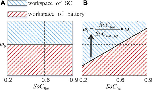
FIGURE 4. (A) Traditional LPF power distribution diagram, (B) self-adaptive LPF power distribution diagram considering
With the self-adaptive LPF power distribution method, the new reference current
In the power distribution control strategy, the DC bus voltage is controlled by the PV and the HESS.
In order to stabilize the DC bus voltage,
When the energy emitted by the system can satisfy (5),
Figure 5 is the dual-loop control block diagram with a power feedforward. The proportional and integral gain of the PI controllers are
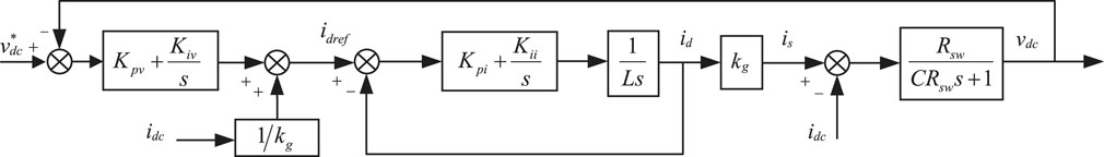
FIGURE 5. Dual-loop control structure of the inverter.
According to Figure 1, the mathematical model of the grid-connected inverter under the dq axis is as follows:
where
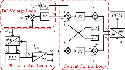
FIGURE 6. Topology diagram of the control system.
According to (7),
According to (8), the power feedforward item
The voltage loop control is to maintain the power balance and stabilize the DC side voltage (Harnefors et al., 2007). The introduction of a power feedforward link will reduce the signal of the outer loop voltage control command, thereby reducing the steady-state error of vdc, improving the response speed. Figure 7 compares the frequency characteristic curve of
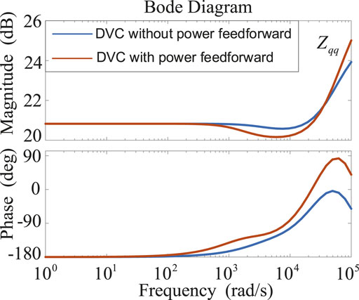
FIGURE 7. Frequency characteristics of
The model of output impedance is built in d-q axis. In order to distinguish the variables of the system and the control loop, the superscript
In the formula,
As mentioned, the inverter uses PLL to obtain the phase information of the grid voltage. The angle output by the PLL will then be used for the d-q axis conversion inside the inverter, so the dynamic characteristics of the PLL will affect the output voltage, current, and duty ratio signals of the inverter, which in turn affects its output impedance (Bakhshizadeh et al., 2016) Eq. 13 is the transfer function of PLL.
where,
When a small signal disturbance is applied to the output voltage, the relationship between the control loop voltage
In the same way, the duty ratio signal has the following relationship:
For the control loop inductor current, there is the following relationship:
The ACC control loop in Figure 8 is realized by converting the system output current
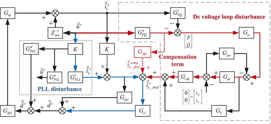
FIGURE 8. Small signal model of the grid-connected inverter with PLL, ACC, and DVC.
Ignoring the power loss of switching devices, the active power balance equation is as follows:
Add a small signal disturbance the
In the formula,
The input current
Set
The transfer function matrix
To obtain the impedance model of the inverter, supposing that on the DC side of the inverter, besides the DC voltage
Let the power feedforward term
Therefore, according to Figure 8, the output impedance matrix of the grid-connected inverter small-signal model can be derived as follows:
Under weak grid conditions, the increase of
In Figure 9A, the Nyquist curves of the impedance ratio are shown. As
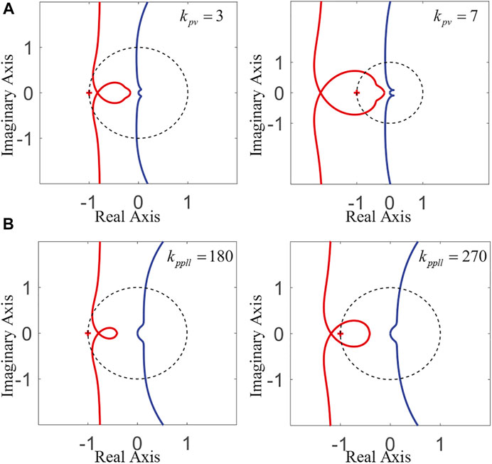
FIGURE 9. (A) Impedance ratio curves of different
In a weak grid, the PLL and the grid impedance are coupled with each other, and the voltage at the PCC point is distorted. The increase in
In Figure 9B, it can be seen that as
Aiming at the problem that the grid impedance, the PLL, and the DC voltage loop are coupled with each other, corresponding control methods need to be adopted to suppress unstable factors.
The disturbance path of the DC voltage loop in Figure 8 shows that
Compensation signal:
Since
Figure 10 shows the disturbance path of the PLL, where the voltage at the PCC point passes through the transfer matrix
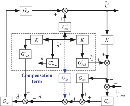
FIGURE 10. Small-signal model of the grid-connected inverter.
According to Figure 10, let the compensation term
Due to the control voltage being
where
Since
The adjustment gain
Figure 11 of the current loop control system with compensation terms is shown in, where
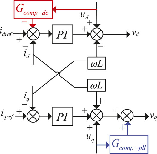
FIGURE 11. Diagram of the current loop control system with compensation terms.
This section uses the data in Table 1 to analyze the frequency characteristics of the inverter output impedance based on the previous deduction.
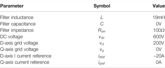
TABLE 1. Grid-Connected system parameters.
Comparison of simulation results of impedance frequency characteristics with and without Gcomp−dc is shown in Figure 12.

FIGURE 12. Impedance frequency characteristics with and without
It can be seen from the figure that when the PLL is acting, the output angle of the PLL is affected by the q-axis voltage, and
After adding
Figure 13 shows the impedance frequency characteristics with and without
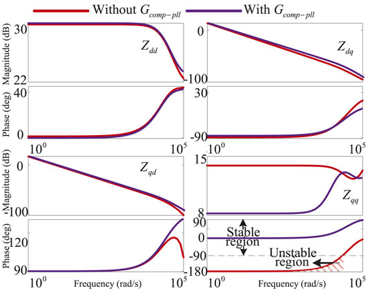
FIGURE 13. Impedance frequency characteristics with and without
The negative influence of PLL on the q-axis makes
As shown in Figure 14, the inverter current vector is synchronized with the grid voltage vector. Assuming that the inverter only delivers active power to the grid, when the disturbance occurs on the q-axis, the voltage vector will transition from the original equilibrium state
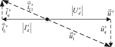
FIGURE 14. Phasor diagram of the inverter when perturbation happens in q channel.
The amplitude of grid voltage remains unchanged, and as the grid-connected power becomes larger, the amplitude of
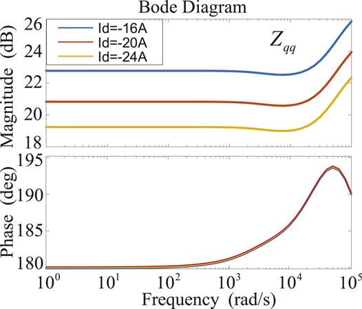
FIGURE 15. Frequency characteristics of
In Figure 15, different grid-connected power has no effect on the phase angle of
In Figure 13, the addition of the compensation term not only eliminates the negative impedance characteristic of
In order to verify the validity of the proposed control strategy, a HIL simulation platform was built in the OPAL-RT real-time simulation system which comprises an external controller and simulation computer. Figure 16 is the OPAL-RT HIL system structure diagram. The host computer (Host PC) is used to build the system model and download it to the target computer (OP5600) through the TPC/IP channel; the target computer uploads information to the Host PC to monitor the operation of the model in real time. The grid-connected inverter controller adopts the TMS320F28335 digital signal processor (DSP). The DSP controller is responsible for collecting model output signals, performing real-time calculations, and generating PWM signals to send to the I/O board of the target machine to control the inverter.
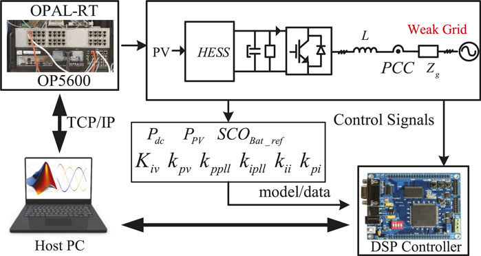
FIGURE 16. HIL experiment topology.
When the output power of the PV array fluctuates:
Figure 17 shows the control experiment results of the PV and energy storage system under case 1.
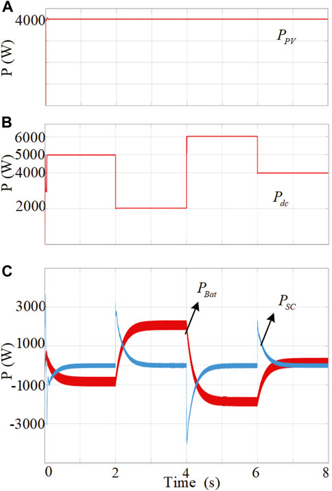
FIGURE 17. (A) DC bus output power
Figure 18 compares the waveforms of the vdc in different energy storage systems versus
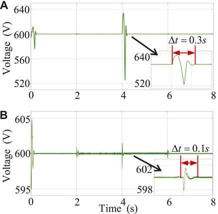
FIGURE 18. (A)
When the output power of the DC bus fluctuates:
Figure 19 shows the control experiment results of the PV and energy storage system in case 2. At first
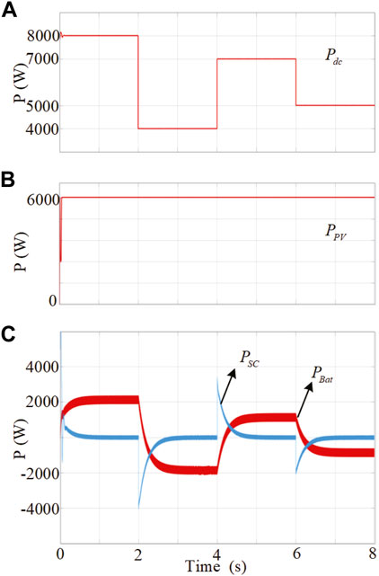
FIGURE 19. (A) DC bus output power
Figure 20 compares the waveforms of the
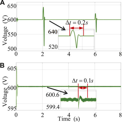
FIGURE 20. (A)
In order to suppress the negative impact of DVC and PLL, the experimental results of the improved method for the traditional inverter control strategy are as follows. Figures 21, 22 show the simulation results of the grid-connected current before and after the compensation control is added to the inverter. The addition of the DVC compensation proposed in this article effectively eliminates the negative impact of the DC voltage loop, and the harmonic distortion rate of the grid-connected current is reduced from 4.18% to 1.02%. The system becomes stable and meets the grid-connected standards. The harmonic distortion rate of the grid-connected current is reduced from 1.02% to 0.68% when the negative influence of the PLL is compensated on the q-axis, which proves the validity of the control method proposed in this study.
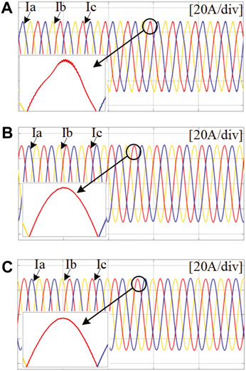
FIGURE 21. Grid-connected current waveform; (A) without compensation; (B) with DVC compensation; (C) with PLL compensation.
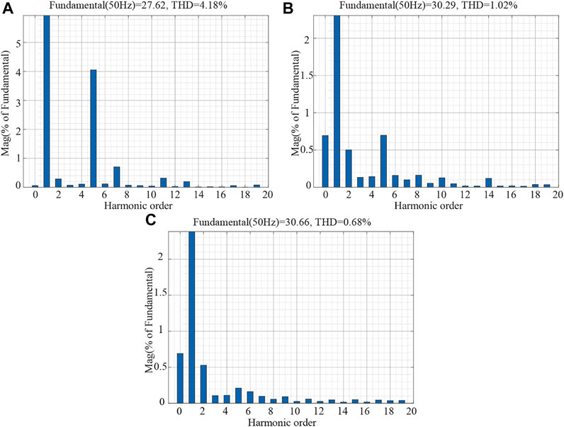
FIGURE 22. Grid-connected current THD; (A) traditional control without compensation; (B) with DVC compensation; (C) with PLL compensation.
In Figure 23, the experimental results show that in the very weak-grid condition, after compensation is added at 0.5 s, the distortion of the grid current is suppressed. The grid-connected system is restored to a stable state.
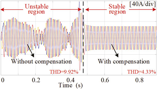
FIGURE 23. Grid-connected current under very weak-grid.
The common fault in the grid-connected operation of the PV system is simulated. The single-phase grounding fault current is measured at the PCC point. When a single-phase ground fault occurs at the PCC point, the grid-connected current will change rapidly. A-phase ground fault occurs at 0.9 s. At 1.2 s, the A-phase ground fault is eliminated. The experimental results are shown in Figure 24. When phase A is grounded, it increases rapidly and distorts. After the fault is eliminated, the current can quickly recover to the current waveform before the A phase is grounded in about 0.01 s. After adding compensation, due to the negative feedback signal in the DVC compensation, the output current is greatly reduced when the fault occurs, and the current waveform is almost stable. The experimental results show that the proposed control method has a certain anti-interference ability to single-phase ground fault.
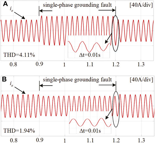
FIGURE 24. Phase-A grounding fault current; (A) without compensation; (B) with compensation.
Aiming at the DC side voltage disturbance of the PV and energy storage system, this study adopts a HESS with a self-adaptive LPF to quickly and effectively stabilize the DC bus voltage. A small-signal model of the grid-connected inverter is established in the dq coordinate system, and the influence of the DC voltage loop and PLL on the output impedance of the inverter is discussed. The DC voltage loop disturbance compensation method based on power feedforward and the PLL disturbance compensation method based on voltage feedforward are proposed. The analysis results of the impedance frequency characteristics and HIL experiment show that the proposed method can reduce the range that the output impedance appears as a negative characteristic, thereby improving the stability of the system.
The original contributions presented in the study are included in the article/Supplementary Material; further inquiries can be directed to the corresponding author.
XL: Investigation, Conceptualization, Methodology, Validation, and Writing—review and editing. CL: Investigation, Conceptualization, Methodology, Software, Writing—original draft, and Writing—review and editing. RW: Supervision and Validation. YZ: Validation and Writing. LZ: Validation and review and editing.
This study is supported by the National Key R&D Program of China under grant (2018YFA0702200), the National Natural Science Foundation of China (62173074), the Key Project of National Natural Science Foundation of China (U20A2019), the State Key Laboratory of Alternate Electrical Power System with Renewable Energy Sources (Grant No. LAPS22002).
The authors declare that the research was conducted in the absence of any commercial or financial relationships that could be construed as a potential conflict of interest.
All claims expressed in this article are solely those of the authors and do not necessarily represent those of their affiliated organizations, or those of the publisher, the editors, and the reviewers. Any product that may be evaluated in this article, or claim that may be made by its manufacturer, is not guaranteed or endorsed by the publisher.
Akram, U., Khalid, M., and Shafiq, S. (2018). Optimal Sizing of a Wind/solar/battery Hybrid Grid‐connected Microgrid System. IET Renew. Power Gener. 12, 72–80. doi:10.1049/iet-rpg.2017.0010
Bakhshizadeh, M. K., Wang, X., Blaabjerg, F., Hjerrild, J., Kocewiak, Ł., Bak, C. L., et al. (2016). Couplings in Phase Domain Impedance Modeling of Grid-Connected Converters. IEEE Trans. Power Electron. 31, 6792–6796. doi:10.1109/TPEL.2016.2542244
Cao, W., Ma, Y., Yang, L., Wang, F., and Tolbert, L. M. (2017). D-Q Impedance Based Stability Analysis and Parameter Design of Three-Phase Inverter-Based AC Power Systems. IEEE Trans. Ind. Electron. 64, 6017–6028. doi:10.1109/tie.2017.2682027
Cespedes, M., and Sun, J. (2014). Adaptive Control of Grid-Connected Inverters Based on Online Grid Impedance Measurements. IEEE Trans. Sustain. Energy 5, 516–523. doi:10.1109/tste.2013.2295201
Davari, M., and Mohamed, Y. A.-R. I. (2016). Robust Vector Control of a Very Weak-Grid-Connected Voltage-Source Converter Considering the Phase-Locked Loop Dynamics. IEEE Trans. Power Electron. 32, 977–994. doi:10.1109/TPEL.2016.2546341
Dong, D., Wen, B., Boroyevich, D., Mattavelli, P., and Xue, Y. (2014). Analysis of Phase-Locked Loop Low-Frequency Stability in Three-phase Grid-Connected Power Converters Considering Impedance Interactions. IEEE Trans. Industrial Electron. 62, 310–321. doi:10.1109/TIE.2014.2334665
Harnefors, L., Bongiorno, M., and Lundberg, S. (2007). Input-admittance Calculation and Shaping for Controlled Voltage-Source Converters. IEEE Trans. Ind. Electron. 54, 3323–3334. doi:10.1109/tie.2007.904022
Harnefors, L., Wang, X., Yepes, A. G., and Blaabjerg, F. (2015). Passivity-based Stability Assessment of Grid-Connected Vscs—An Overview. IEEE J. Emerg. Sel. Top. Power Electron. 4, 116–125. doi:10.1109/JESTPE.2015.2490549
Jing, W., Hung Lai, C., Wong, S. H. W., and Wong, M. L. D. (2017). Battery‐supercapacitor Hybrid Energy Storage System in Standalone DC Microgrids: Areview. IET Renew. Power Gener. 11, 461–469. doi:10.1049/iet-rpg.2016.0500
Lu, D., Wang, X., and Blaabjerg, F. (2018). Impedance-based Analysis of Dc-Link Voltage Dynamics in Voltage-Source Converters. IEEE Trans. Power Electron. 34, 3973–3985. doi:10.1109/TPEL.2018.2856745
Nicolini, A., Pinheiro, H., Carnielutti, F., and Massing, J. (2020). PLL Parameters Tuning Guidelines to Increase Stability Margins in Multiple Three‐phase Converters Connected to Weak Grids. IET Renew. Power Gener. 14, 2232–2244. doi:10.1049/iet-rpg.2020.0028
Sun, J. (2011). Impedance-based Stability Criterion for Grid-Connected Inverters. IEEE Trans. Power Electron. 26, 3075–3078. doi:10.1109/tpel.2011.2136439
Tricarico, T., Gontijo, G. F., Aredes, M., Dias, R., and Guerrero, J. M. (2020). New Hybrid‐microgrid Topology Using a Bidirectional Interleaved Converter as a Robust Power Interface Operating in Grid‐connected and Islanded Modes. IET Renew. Power Gener. 14, 134–144. doi:10.1049/iet-rpg.2019.0626
Wang, X., Li, Y. W., Blaabjerg, F., and Loh, P. C. (2014). Virtual-impedance-based Control for Voltage-Source and Current-Source Converters. IEEE Trans. Power Electron. 30, 7019–7037. doi:10.1109/TPEL.2014.2382565
Wang, X., Ruan, X., Liu, S., and Tse, C. K. (2010). Full Feedforward of Grid Voltage for Grid-Connected Inverter with Lcl Filter to Suppress Current Distortion Due to Grid Voltage Harmonics. IEEE Trans. Power Electron. 25, 3119–3127. doi:10.1109/tpel.2010.2077312
Wen, B., Boroyevich, D., Burgos, R., Mattavelli, P., and Shen, Z. (2015a). Analysis of Dq Small-Signal Impedance of Grid-Tied Inverters. IEEE Trans. Power Electron. 31, 675–687. doi:10.1109/TPEL.2015.2398192
Wen, B., Boroyevich, D., Burgos, R., Mattavelli, P., and Shen, Z. (2014). Small-signal Stability Analysis of Three-phase Ac Systems in the Presence of Constant Power Loads Based on Measured Dq Frame Impedances. IEEE Trans. Power Electron. 30, 5952–5963. doi:10.1109/TPEL.2014.2378731
Wen, B., Dong, D., Boroyevich, D., Burgos, R., Mattavelli, P., and Shen, Z. (2015b). Impedance-based Analysis of Grid-Synchronization Stability for Three-phase Paralleled Converters. IEEE Trans. Power Electron. 31, 26–38. doi:10.1109/TPEL.2015.2419712
Xu, D., and Cen, H. (2021). A Hybrid Energy Storage Strategy Based on Multivariable Fuzzy Coordinated Control of Photovoltaic Grid‐connected Power Fluctuations. IET Renew. Power Gener. 15, 1826–1835. doi:10.1049/rpg2.12152
Xu, J., Xie, S., Qian, Q., and Zhang, B. (2017). Adaptive Feedforward Algorithm without Grid Impedance Estimation for Inverters to Suppress Grid Current Instabilities and Harmonics Due to Grid Impedance and Grid Voltage Distortion. IEEE Trans. Ind. Electron. 64, 7574–7586. doi:10.1109/tie.2017.2711523
Xue, M., Zhang, Y., Kang, Y., Yi, Y., Li, S., and Liu, F. (2012). Full Feedforward of Grid Voltage for Discrete State Feedback Controlled Grid-Connected Inverter with Lcl Filter. IEEE Trans. Power Electron. 27, 4234–4247. doi:10.1109/tpel.2012.2190524
Yang, D., Ruan, X., and Wu, H. (2014). Impedance Shaping of the Grid-Connected Inverter with Lcl Filter to Improve its Adaptability to the Weak Grid Condition. IEEE Trans. Power Electron. 29, 5795–5805. doi:10.1109/tpel.2014.2300235
Yang, L., Chen, Y., Luo, A., Chen, Z., Zhou, L., Zhou, X., et al. (2019). Effect of Phase‐locked Loop on Small‐signal Perturbation Modelling and Stability Analysis for Three‐phase LCL‐type Inverter Connected to Weak Grid. IET Renew. Power Gener. 13, 86–93. doi:10.1049/iet-rpg.2018.0072
Yuan, H., Yuan, X., and Hu, J. (2017). Modeling of Grid-Connected Vscs for Power System Small-Signal Stability Analysis in Dc-Link Voltage Control Timescale. IEEE Trans. Power Syst. 32, 3981–3991. doi:10.1109/tpwrs.2017.2653939
Zhang, X., Xia, D., Fu, Z., Wang, G., and Xu, D. (2018). An Improved Feedforward Control Method Considering Pll Dynamics to Improve Weak Grid Stability of Grid-Connected Inverters. IEEE Trans. Ind. Appl. 54, 5143–5151. doi:10.1109/tia.2018.2811718
Keywords: PV and energy storage system, weak power grids, grid-connected inverter, phase-locked loop, stability analysis
Citation: Li C, Liu X, Wang R, Zhang Y and Zhang L (2022) An Improved Dual-Loop Feedforward Control Method for the Enhancing Stability of Grid-Connected PV and Energy Storage System Under Weak Grids. Front. Energy Res. 10:939376. doi: 10.3389/fenrg.2022.939376
Received: 09 May 2022; Accepted: 30 May 2022;
Published: 22 July 2022.
Edited by:
Qihe Shan, Dalian Maritime University, ChinaReviewed by:
Kenneth E. Okedu, National University of Science and Technology (Muscat), OmanCopyright © 2022 Li, Liu, Wang, Zhang and Zhang. This is an open-access article distributed under the terms of the Creative Commons Attribution License (CC BY). The use, distribution or reproduction in other forums is permitted, provided the original author(s) and the copyright owner(s) are credited and that the original publication in this journal is cited, in accordance with accepted academic practice. No use, distribution or reproduction is permitted which does not comply with these terms.
*Correspondence: Xinrui Liu, bGl1eGlucnVpQGlzZS5uZXUuZWR1LmNu
Disclaimer: All claims expressed in this article are solely those of the authors and do not necessarily represent those of their affiliated organizations, or those of the publisher, the editors and the reviewers. Any product that may be evaluated in this article or claim that may be made by its manufacturer is not guaranteed or endorsed by the publisher.
Research integrity at Frontiers
Learn more about the work of our research integrity team to safeguard the quality of each article we publish.