 Chunyu Yin
 Rong Liu
 Yongjun Jiao1
 Shengyu Liu
94% of researchers rate our articles as excellent or good
Learn more about the work of our research integrity team to safeguard the quality of each article we publish.
Find out more
ORIGINAL RESEARCH article
Front. Energy Res., 07 July 2022
Sec. Nuclear Energy
Volume 10 - 2022 | https://doi.org/10.3389/fenrg.2022.936288
In this article, a simulation code for tritium diffusion behavior analysis in FeCrAl cladding is developed based on the COMSOL platform. The simulated results are in good agreement with experimental and theoretical results. The effects of different concentrations of tritium and temperature distributions on the diffusion behavior of tritium in FeCrAl cladding were further investigated. Finally, the optimal effect of different coating schemes on the tritium resistance of the FeCrAl cladding was investigated. The results show that higher temperatures lead to higher cladding diffusion coefficients, which will further lead to higher fluxes of tritium into and out of the cladding, which is found to further result in a higher tritium flux into and out of the cladding, as well as shorter tritium diffusion times. It is found that higher temperature will lead to more tritium flux into and out of the cladding and shorter time for the tritium flux to reach a steady state on the right side of the cladding. At the same time, the higher tritium partial pressure on the fuel side of the cladding will lead to a longer time for the tritium flux to reach a steady state on the water side of the cladding. The longer time to reach the steady state on the water side of the cladding increases the tritium flux into the cladding.
The nuclear accident in Fukushima in Japan has aroused people’s concern about the safety of nuclear reactors in the case of accidents, so there is a growing interest in the research and development of accident-tolerant fuel, and the accident-tolerant fuel could have a higher safety margin in the case of loss of coolant accident (LOCA). The FeCrAl alloy can form Cr2O3 and α-Al2O3 protective oxide films under high-temperature water vapor above 800°C, which can alleviate or even avoid the problem of zirconium water reaction under LOCA conditions, and can greatly improve the safety margin of light water reactor. Therefore, the FeCrAl alloy is one of the candidate cladding materials for accident-tolerant fuel (Terrani et al., 2014; Rebak, 2020; Garud et al., 2022). FeCrAl usually contains 10–15 wt% Cr and 3–6 wt% Al. It has a body-centered cubic crystal structure and a high melting point (about 1,500°C) together with excellent oxidation resistance (Print et al., 2013). However, the use of FeCrAl alloys also poses the problem of increasing the concentration of tritium in the coolant, a radioactive element that emits beta rays and has a half-life of 450 days (Lucas and Unterweger, 2000). The annual emission of gaseous tritium should not exceed 1.5 × 10¹³ Bq for a light water reactor with a thermal power of 3000 MW, liquid tritium emission should not exceed 7.5 × 10¹³ Bq, and gaseous tritium emission should not exceed 4.5 × 10¹³ Bq for heavy water reactors. Tritium is one of the radionuclides released into the environment from nuclear power plants, and is also the main radionuclide dose evaluation in nuclear facilities. The ternary fission reaction of nuclear fuel in light water reactors is one of the main sources of tritium. The transmittance of tritium in FeCrAl is two orders of magnitude higher than in zirconium alloy, which could lead to more tritium diffusion into the coolant and increase its tritium content, thus affecting the separation and emission strategy of tritium in nuclear power plants. Therefore, there is a need to study the diffusion behavior of tritium in FeCrAl alloys.
Currently, an effective method to prevent tritium diffusion is to coat the surface of the cladding with a low diffusion coefficient of tritium to delay the entry of tritium into the coolant and reduce the amount of tritium released into the coolant during the fuel rod irradiation period. Yeom et al. (2019) studied the corrosion resistance of zircalloy cladding, which was coated with Cr in high-temperature steam, and the results also showed that Cr coating provided stable corrosion resistance for zircalloy cladding. Recently, Yeo et al. (2022) studied the barrier effect of plasma nitride Cr coating and untreated Cr coating on chemical elements, and the results of the study showed that plasma nitride Cr coating has better chemical barrier effect. Lee et al. (2019) studied the corrosion resistance of SiC/SiC composite cladding coated with Cr in high-temperature steam. By analyzing the experimental results, it was concluded that Cr coating had excellent corrosion resistance at high temperature and could effectively protect the cladding from steam corrosion.
There are many reports on the diffusion behavior of tritium in cladding alloys, and many researchers have made experimental measurement on the diffusion of hydrogen (tritium) in FeCr alloys and FeCrAl alloys. In the early stage, Huffin and Williams conducted a hydrogen permeability measurement study on the FeCrAl alloy (20% Cr, 5% Al, and 75% Fe) and 446 stainless steel (25% Cr and 75% Fe) (Huffine and Williams, 1960), considering the conditions with and without oxidation layer. Although the study was conducted at relatively high temperatures (922–1,450 K), the researchers found that hydrogen permeability was about three orders of magnitude smaller in alloys with oxide layers than in alloys without oxide layers. Then Stempien developed a tritium transport model to predict its behavior in heat exchanger tubes for fluoride salt-cooled high-temperature reactors during reactor startup (Stempien, 2015). Furthermore, Hu et al. (2015) from Tennessee State University, experimentally measured the hydrogen permeability of the three types of FeCrAl alloys in the temperature range of 350–650°C, and found that the permeability of hydrogen in FeCrAl alloy is about 3–5 times higher than that of 304 stainless steels at 650 and 350°C, so temperature also has a great influence on permeability. The higher the Cr content, the lower the permeability. Furthermore, a one-dimensional diffusion model of tritium in FeCrAl alloy was established based on the BISON code (Hales et al., 2016), the tritium content in the coolant was estimated, and a tritium resistance scheme was proposed by coating the inner surface of the cladding material with aluminum oxide. In addition, the BISON code developed by Idaho National Laboratory also analyzed the diffusion behavior of hydrogen in the fuel and cladding (Hales et al., 2016). Based on Fick’s law and taking into account the Soret effect, this study revealed the main input parameters and environmental conditions affecting hydrogen distribution. Meanwhile, Zhou and Tong (2021) from Shanghai Jiao Tong University developed a one-dimensional simulation program of modeling tritium diffusion behavior in zirconium alloys based on the tritium diffusion model, and analyzed the effect of different tritium concentration and temperature distribution on tritium diffusion behavior in zirconium cladding. Previously, there were many codes developed for investigating hydrogen diffusion behavior and its isotopes in structure materials; typical codes are TRITGO from Oak Ridge National Laboratory (Hanson et al., 2006), TPAC and TMAP codes from Idaho National Laboratory (Eung et al., 2010), THYTAN code from Japan Atomic Energy Agency (Longhurst, 2004), and TBEC code from Korea Advanced Institute of Science and Technology (Ohashi and Sherman, 2007). Among these codes, TRITGO, THYTAN, and TPAC codes can simulate tritium diffusion behavior in a large range and can cover full reactor core calculation. TBEC and TMAP code adopted a differential method to solve the tritium diffusion equation based on Fick’s law, and compared with Sievert’s law method, more attention is paid to tritium diffusion behavior in structural materials. In this article, based on the diffusion model of tritium in cladding materials, a numerical simulation code of investigating tritium diffusion behavior in FeCrAl alloys was developed on the COMSOL platform, and the code was verified by a typical case. Then, the diffusion of tritium in FeCrAl alloy cladding materials at different concentrations and temperatures was analyzed. Finally, tritium migration and concentration distributions were calculated for coatings with different types, thicknesses, and defects. The effect of different tritium blocking schemes on the tritium blocking performance of the FeCrAl cladding was also investigated.
The tritium diffusion code developed in this work considers the diffusion behavior under the influence of temperature change. Therefore, the heat transfer model and diffusion model are selected to be considered in the development of tritium diffusion code in the FeCrAl cladding.
The heat transfer model of the fuel is determined by the following heat transfer equation:
where (K) is the temperature;
where
The heat transfer in the gap between the fuel and the cladding is modeled using a one-dimensional steady-state heat transfer model, where the radial heat flux is calculated as:
where
Tritium is released into the coolant after it is generated in the reactor core in four main stages: 1) diffusion in the core fuel, 2) entry into the gap between the fuel and the cladding, 3) adsorbed by the inner surface of the cladding, and 4) diffusion in the cladding material and its oxide layer, and release into the coolant. The diffusion process is influenced by the temperature distribution, tritium concentration, tritium diffusion coefficient, and the multilayer structure of the FeCrAl alloy.
Diffusion occurs when there is a chemical potential gradient of hydrogen isotopes in the FeCrAl alloy, such as a concentration gradient and a temperature gradient. Diffusion due to concentration gradients follows Fick’s law, as shown in Equation (4), that is, under steady-state diffusion conditions, the mass of the diffusible material per unit time passing through a unit area perpendicular to the direction of diffusion is proportional to the concentration gradient of that cross-section:
where C is the solid-solution tritium concentration in atom·m−3;
The diffusion coefficient of hydrogen isotopes is also affected by the temperature distribution, and is found to increase with an increasing temperature, as shown in Equation 5:
where D is the diffusion coefficient, m2·s−1.
For the three isotopes of hydrogen, deuterium, and tritium, the ratio of their diffusivity is theoretically considered to be inversely proportional to the square root of their atomic weight:
Sawatzky (1960) found that temperature gradients in a material not only affects the diffusion coefficient, but may also drive diffusion directly, a phenomenon known as the thermal diffusion effect. The expression for the thermal diffusion flux is given as:
where
Thus, the diffusion of hydrogen isotopes in materials where a temperature gradient exists is the result of coupled thermal diffusion and concentration gradient diffusion:
where t is the time in s and
The rate of tritium production in the fuel is determined by the operating conditions of the reactor. According to the calculations of Katakura (2012), for a fuel element with a diameter of 8.2 mm, assuming the linear power of the fuel element is 220 W·cm−1, the power density is 416.6 W·cm−3 for the fuel element, and we can get the fission rate as 1.26×10¹³ fissions·cm−3·s−1, the amount of tritium produced in this process is 1.18 × 10⁻⁴ atom/fission, so the tritium production rate is approximately 1.335×10⁹ atoms/cm3/s. According to Dolle et al.’s estimation (Dollè et al., 1980), 50% of the tritium produced in the fuel will be released into the gap between the fuel and the cladding.
The concentration of tritium diffusing from the gap to the cladding inner surface can be calculated by the following equation:
where
Assuming that tritium is in local equilibrium at the interface between the gap and the cladding, which means that tritium cannot accumulate on this surface, the flux from the gap to the cladding surface is equivalent to the flux from the cladding surface to the cladding:
Since the distribution of tritium in the gap is assumed to be uniform, the expression for the tritium flux from the gap to the cladding can be derived from Equations 7, 8 as:
where a is the ratio of the gap volume to the cladding inner surface area in m.
According to Sievert’s law, tritium concentration is proportional to
where S is the solubility of tritium in the cladding material;
The boundary conditions are derived from Equations 7 to 10 and Fick’s law:
1. Boundary conditions at the cladding inner surface:
2. Boundary conditions at the cladding outer surface:
3. Based on Fick’s law, the diffusion of tritium in the cladding was calculated as follows:
where
The tritium concentration distribution in the cladding is calculated by solving Equations 11–13 based on the COMSOL platform and compared with the reported data and simulated results of BISON’s model (O’Neal, 2021; O’Neal et al., 2022). The comparison results are presented in Figures 1–3 (O’Neal, 2021; O’Neal et al., 2022), which show the distribution of tritium concentration in the radial direction in the FeCrAl cladding at 10,000; 50,000; and 120,000 s, respectively. From these figures, it could be seen that the calculated results by COMSOL can accurately simulate the distribution of tritium concentration in the cladding at different time, and the COMSOL calculated result is found to be closer to the reported concentration distribution than that of the BISON calculation. Figure 4 shows tritium distribution in the cladding calculated by COMSOL.
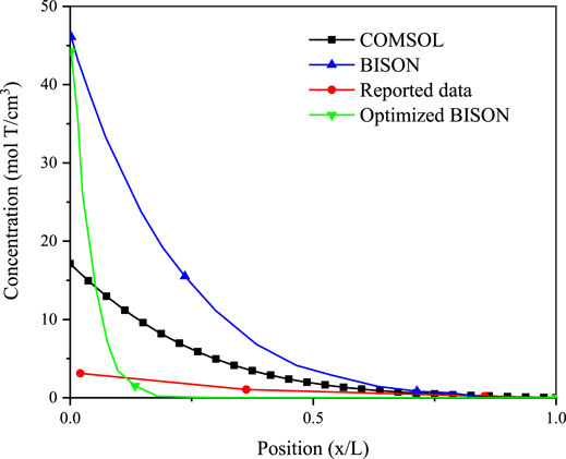
FIGURE 1. Tritium distribution at the radial direction in the FeCrAl cladding of simulated and experimental results at 10,000 s, and concentrations are times 1012.
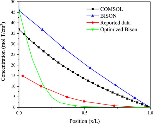
FIGURE 2. Tritium distribution at the radial direction in the FeCrAl cladding of simulated and experimental results at 50,000 s, and concentrations are times 1012.
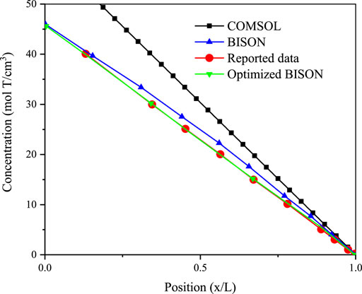
FIGURE 3. Tritium distribution at the radial direction in the FeCrAl cladding of simulated and experimental results at 120,000 s, and concentrations are times 1012.
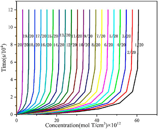
FIGURE 4. Tritium distribution in the FeCrAl cladding at the end of the simulation.
According to Equation 5, the tritium diffusivity may differ significantly under different temperature conditions, so the effect of temperature on tritium diffusion behavior are investigated in this work. Figures 5, 6 show the effect of different temperatures on tritium flux into the cladding inner and outer surface. It could be seen that the flux of tritium into and out of the FeCrAl cladding is affected by different temperature above 700 K, and this is mainly ascribed to the effect of temperature on the diffusion coefficient of tritium in FeCrAl, in which the effect of temperature on the diffusion coefficient is exponential. The diffusion coefficient of tritium is found to increase with increasing temperature, and the rate of tritium entering and leaving the cladding. It could be seen from Figure 6 that the time to reach the steady state of the tritium concentration at the cladding outer side is about 30 s at 573.15 K, about 20 s at 673.15 K, and the shortest time, about 10 s, when the cladding temperature is 873.15 K. This is because the time to reach the steady state of tritium concentration at the cladding outer side will be shortened when the temperature increases and then the diffusion process will be accelerated.
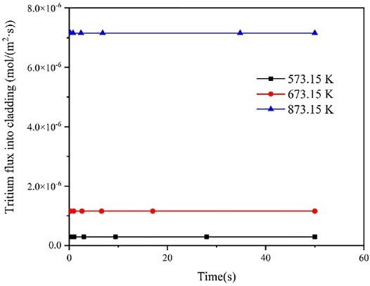
FIGURE 5. Effect of different temperature on tritium flux into the cladding inner surface.
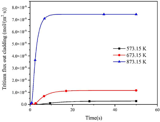
FIGURE 6. Effect of different temperature on tritium flux out of the cladding outer surface.
Since the concentration of tritium at the inner surface of cladding is affected by the partial pressure of tritium in fuel rods, the effect of different internal pressure of fuel rods on the diffusion behavior of tritium in the FeCrAl cladding was studied in this work, as shown in Figures 7 and 8. It could be seen that different pressure has a big effect on the flux of tritium into and out of the FeCrAl cladding, which is mainly due to the fact that the internal pressure of the fuel rod affects the partial pressure of tritium inside the cladding. According to Figure 7, it could be seen that when the fuel rod internal pressure increases, the time for the tritium flux at the cladding outer surface to reach a steady state will increase. This is because an increase in the fuel rod internal pressure will increase the tritium concentration at the cladding inner surface for the steady-state case, while the tritium diffusion in the cladding does not change, therefore the time to reach a steady state will increase.
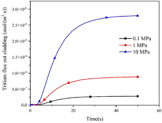
FIGURE 7. Effect of different fuel rod internal pressures on tritium flux rates on the cladding outer surface.
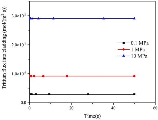
FIGURE 8. Effect of different fuel rod internal pressures on tritium flux rates on the cladding inner surface.
In this section, the tritium diffusion code for the FeCrAl cladding with different coating schemes were considered. To save computing resources and reduce computing time, only the geometric construction of the cladding was carried out in this study, and since tritium diffusion and heat transfer in the axial direction were not considered, the height of the cladding was set as 1 mm. Two different coating schemes (i.e., coating on cladding inner and outer surface, respectively) were explored as our tritium barrier scheme. The specific geometric parameters are listed in Table 1.

TABLE 1. The parameters of geometry.
In this work, different types of coatings, different coating thicknesses, and different coating defect were studied. Among them, Cr, Cr2O3, and Al2O3 were selected as the three types of coating, and the tritium diffusion coefficients of different coatings were obtained by the first-principles calculation. In order to improve the simulation accuracy, an incremental partition method was used to divide the radial nodes of the cladding, where the width ratio of the widest mesh to the narrowest mesh was 10. The simulation parameters are summarized in Table 2. The tritium diffusion coefficients of different coatings are listed in Table 5. The detailed computational mesh is shown in Figure 9.
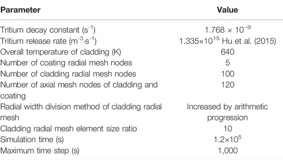
TABLE 2. Simulation parameters.

FIGURE 9. The computational mesh of FeCrAl cladding with coating.
Based on our validated code, tritium diffusion was simulated to investigate the effect of coating thickness. Since the diffusion mechanism of tritium is the same in different coatings, Cr was selected as a representative coating for the simulation. The coating thickness, coating position, and relevant simulation parameters of the coating are listed in Table 3.
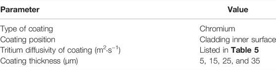
TABLE 3. Simulation parameters of cladding with different coating thickness.
As shown in Figure 10, the concentration distribution of tritium in the FeCrAl cladding with different coating thickness at 1.2 × 10⁵ s was compared. According to the concentration scale in Figure 10 and the concentration distribution broken line in Figure 11, the coating thickness is found to have negligible influence on the concentration distribution of tritium inside the cladding. However, due to the limitation of manufacturing process, it is impossible to coat the surface of the cladding with excessive thickness. Therefore, 5-μm thick coating could be adopted as the best thickness choice.
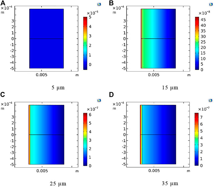
FIGURE 10. Tritium concentration distribution at 1.2 × 10⁵ s for the Cr coating with different coating thickness. (A) 5 μm, (B) 15 μm, (C) 25 μm, and (D) 35 μm.
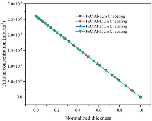
FIGURE 11. Radial tritium concentration distribution in the FeCrAl cladding with different thickness.
Tritium migration was simulated with different coating positions and defect. The type of coating, coating position, coating defect, and relevant simulation parameters are listed in Table 4.

TABLE 4. Parameters of coating with different coating positions and defect.
In this work, the chromium coating was selected as the representative coating for the simulation. Three comparison points, namely, 10,000; 50,000; and 120,000 s, were selected to analyze the tritium distribution in the FeCrAl cladding with different coating defects. The tritium distribution in the FeCrAl cladding with different coatings at t = 120,000 s is shown in Figure 12, and the tritium distribution in the radial direction for the cladding with coating defects at different positions at t = 120,000 s is shown in Figure 13. As can be seen from Figures 12 and 13, the concentration of tritium in the outer surface coating was found to be higher than that in the inner surface coating at the same time. Moreover, the higher the integrity of the coating, the higher the concentration of tritium accumulated in the coating.
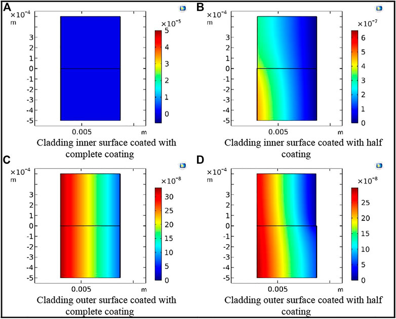
FIGURE 12. Tritium concentration distribution in the cladding with different coating defects at t = 120,000 s. (A) Cladding inner surface coated with complete coating. (B) Cladding inner surface coated with half coating. (C) Cladding outer surface coated with complete coating. (D) Cladding outer surface coated with half coating.
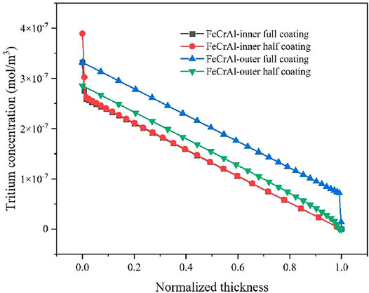
FIGURE 13. Radial tritium concentration distribution at t = 10,000 s.
Figure 14 compares the total amount of tritium released into the coolant at t = 120,000 s for the cladding coated with different missing states of coating layer. It can be clearly seen that the inner coating scheme could effectively prevent the tritium from entering the cladding and the coolant on the water side. It is important to note that the model used in this work assumes that tritium can be rapidly absorbed at the FeCrAl cladding surface with a tritium concentration of 0. This assumption will lead to the release of tritium. It is expected that the effect of tritium resistance will be better than what is shown in the figure when coating is on the water side of the cladding.
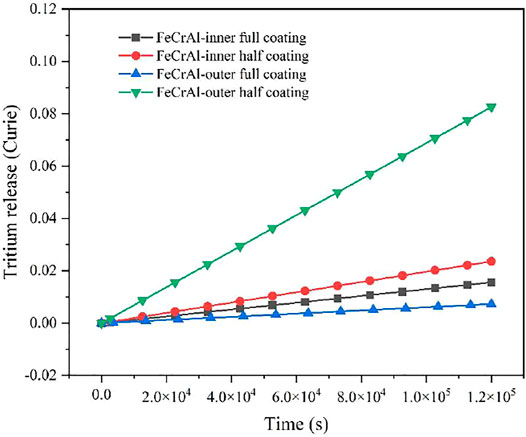
FIGURE 14. Total amount of tritium released to the coolant for FeCrAl cladding with different coating scheme within 120,000 s.
As shown in Figure 15, the axial tritium distribution in the FeCrAl cladding with different coating schemes are compared. We can see from Figure 15 that when the outer surface coating has coating defects, the tritium concentration gradient at the coating defects is large, resulting in an uneven axial tritium distribution. However, when the inner surface coating has coating defects, no significant difference in the tritium concentration was observed at the inner surface of the FeCrAl cladding, thus the difference in axial tritium distribution is small when using the inner coating.
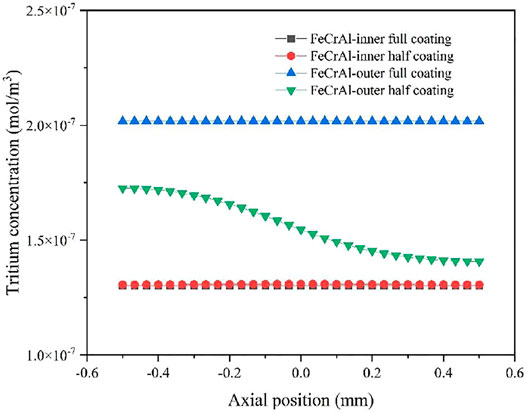
FIGURE 15. Axial tritium distribution in the FeCrAl cladding at 120,000 s.
Figure 16 shows the variation of tritium concentration in the FeCrAl cladding coated with four different types of coating schemes, and we can see that the variation of tritium concentration in the FeCrAl cladding reaches a steady state at 1,000 s.
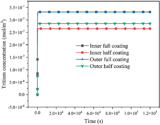
FIGURE 16. Variation of tritium concentration in the FeCrAl cladding coated with four different types of coating schemes. Based on the abovementioned simulation results, it is clear that tritium concentrations of the four different types of coating schemes reach a steady state at t = 10,000 s. There is no significant difference in the tritium concentration distribution within 1.2 × 10⁵ s.
Table 5 summarized the hydrogen diffusion coefficients of three types of coatings, DH, which are calculated by the VASP code, and the tritium diffusion coefficient is calculated based on Equation 6 introduced previously. Then, the tritium distribution in the FeCrAl cladding with different coatings could be calculated, as shown in Figure 17. It could be seen that at the end of the calculated time, the tritium concentration within the cladding was significantly reduced by using the Al2O3 coating layer, so in order to reduce the total amount of tritium within the coolant, the Al2O3 coating scheme could be chosen as the possible solution.

TABLE 5. Hydrogen diffusion coefficient of three types of coatings.
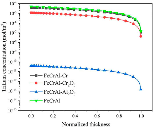
FIGURE 17. Tritium distribution in the FeCrAl cladding with different coatings under a steady state condition.
For FeCrAl cladding coated with different types of coatings, a better tritium resistance scheme is needed to more accurately assess the amount of tritium released into the coolant. In this work, the total amount of tritium released by the abovementioned FeCrAl cladding with three different types of coatings on the inner and outer surfaces of the cladding was calculated as follows:
where
As shown in Figures 18 and 19, it is evidently seen that the amount of tritium released from the three types of the coated FeCrAl cladding is essentially the same when the coating is applied to the inner surface of the FeCrAl cladding, which is due to the essentially same tritium concentration gradient on the outer surface of the FeCrAl cladding. The difference in the total amount of tritium diffused to the coolant is due to the internal and external layout of the cladding, but also to the different tritium diffusion coefficients of the cladding and the zero-concentration boundary conditions at the outer boundary of the cladding resulting in different concentration gradients at the outer surface of the cladding. The reduction in tritium release was found to be most pronounced when the coating was applied to the outer surface of the cladding. This is because the tritium diffusion coefficient of the Al2O3 coating is much smaller than that of the Cr and Cr2O3 coating.
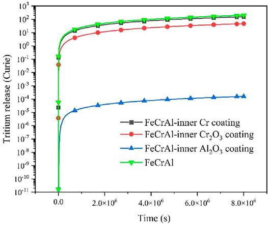
FIGURE 18. Total tritium release when the coating is on the inner surface of the FeCrAl cladding.
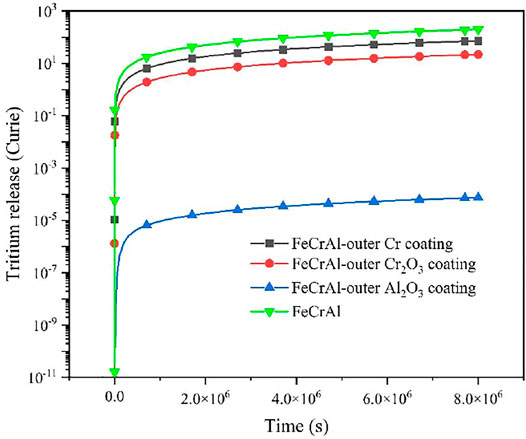
FIGURE 19. Total tritium release when the coating is on the outer surface of the cladding.
In this article, the diffusion behavior of tritium in the FeCrAl cladding considering temperature variation is investigated using the COMSOL multiphysics analysis platform. The accuracy of the numerical tritium diffusion code was verified, and the effects of different temperatures and pressures on the diffusion of tritium in the FeCrAl alloys were studied. Then, the effects of coating thickness, coating integrity, coating location, and different types of coatings as tritium barrier in the FeCrAl cladding were investigated. The conclusions are presented in the following:
1) The higher the cladding temperature, the higher the tritium diffusion coefficient of the FeCrAl cladding, which further reduces the time for tritium flux to reach a steady state on the water side of the cladding.
2) The higher the partial pressure of tritium on the fuel side of the cladding, the higher the tritium flux into the cladding, which results in a longer time for the tritium flux to reach a steady state.
3) The coating thickness is found to have no significant effect on the tritium concentration distribution in the FeCrAl cladding within 1.2 × 10⁵ s.
4) The coating was found to be more effective as a barrier to tritium when it was applied to the inner surface of the cladding, and the effectiveness of tritium resistance was found to be positively correlated with the integrity of the coating.
5) The Al2O3 coating was found to be the most effective against tritium as a barrier to tritium compared to the Cr and Cr2O3 coatings, which can effectively reduce the tritium concentration within the coating.
The original contributions presented in the study are included in the article/Supplementary Material. Further inquiries can be directed to the corresponding authors.
CY: Data curation, investigation, and writing—original draft. RL: Conceptualization, methodology, supervision, writing—review, and editing. YJ: Investigation, validation, writing—review, and editing. SL: Conceptualization, methodology, writing—review, and editing. ZD: Methodology, writing—review, and editing. SG: Investigation, validation, review, and editing. LH: review and editing. PC: Conceptualization, methodology, supervision, writing—review, and editing.
The financial supports from the Nation Key Research and Development Program of China 2019YFB1901000 are highly appreciated.
The authors declare that the research was conducted in the absence of any commercial or financial relationships that could be construed as a potential conflict of interest.
All claims expressed in this article are solely those of the authors and do not necessarily represent those of their affiliated organizations, or those of the publisher, the editors, and the reviewers. Any product that may be evaluated in this article, or claim that may be made by its manufacturer, is not guaranteed or endorsed by the publisher.
Dollè, L., Houdaille, B., Leger, D., and Roth, E. (1980). Tritium in Fission Reactors Production and Management. Paris-Saclay: CEA Centre d'Etudes Nucleaires de Saclay.
Eung, S. K., Chang, H. O., and Patterson, M. (2010). Study on the Tritium Behaviors in the VHTR System. Part 1: Development of Tritium Analysis Code for VHTR and Verification. Nucl. Eng. Des. 240, 1758–1767. doi:10.1016/j.nucengdes.2010.02.023
Garud, Y. S., Hoffman, A. K., and Rebak, R. B. (2022). Hydrogen Isotopes Permeation in Clean or Unoxidized FeCrAl Alloys: A Review. Metall. Mater Trans. A 53, 773–793. doi:10.1007/s11661-021-06535-8
Hales, J. D., Williamson, R. L., Novascone, S. R., Pastore, G., Spencer, B. W., Stafford, D. S., et al. (2016). BISON Theory Manual the Equations behind Nuclear Fuel Analysis. United States: Idaho National Lab. (INL), Idaho Falls, ID United States.
Hanson, D. L., Richards, M. B., and Connors, G. P. (2006). TRITGO Code Description and User’s Guide. San Diego, CA: GA company, GA Project 20128-911081.
Hu, X., Terrani, K. A., Wirth, B. D., and Snead, L. L. (2015). Hydrogen Permeation in FeCrAl Alloys for LWR Cladding Application. J. Nucl. Mater. 461, 282–291. doi:10.1016/j.jnucmat.2015.02.040
Huffine, C. L., and Williams, J. M. (1960). Hydrogen Permeation through Metals, Alloys and Oxides at Elevated Temperatures. Corrosion 16 (9), 430t–432t. doi:10.5006/0010-9312-16.9.102
Katakura, J. (2012). JENDL FP Decay Data File 2011 and Fission Yields Data File 2011. Tokai, Ibaraki, Japan: Japan Atomic Energy Agency, JAEA-Data/Code-2011-025.
Lee, J. J., Takaaki, K., Bruce, P., and Yutai, K. (2019). “High-Temperature Steam Oxidation of Cr-Coated SiCf/SiC Composite for LWR Cladding Applications,” in International Nuclear Fuel Cycle Conference, Seattle, Washington, United States, September 22–27, 2019.
Longhurst, G. R. (2004). TMAP7 User Manual. Idaho Falls, United States: Idaho National Lab. (INL), INL/EXT-04-02352.
Lucas, L. L., and Unterweger, M. P. (2000). Comprehensive Review and Critical Evaluation of the Half-Life of Tritium. J. Res. Natl. Inst. Stand. Technol. 105 (4), 541–549. doi:10.6028/jres.105.043
Ohashi, H., and Sherman, S. (2007). Tritium Movement and Accumulation in the NGNP System Interface and Hydrogen Production. Idaho Falls, ID, United States: Idaho National Lab. (INL), INL/EXT-07-12746.
O’Neal, M. (2021). Assessment of Component Level Tritium Transport for Fission and Fusion Systems. Masters theses. Knoxville: University of Tennessee.
O’Neal, M., Seo, S. B., Maldonado, G. I., and Brown Nicholas, R. (2022). Assessment of BISON Capabilities for Component-Level Prediction of Tritium Transport in Fusion and Fission Applications. Fusion Eng. Des. 175, 112996. doi:10.1016/j.fusengdes.2021.112996
Print, B. A., Terrani, K. A., Brady, M. P., Cheng, T., and Keiser, J. R. (2013). High Temperature Oxidation of Fuel Cladding Candidate Materials in Steam-Hydrogen Environments. J. Nucl. Mater. 440, 420–427. doi:10.1016/j.jnucmat.2013.05.047
Rebak, R. B. (2020). Accident Tolerant Materials for Light Water Reactor Fuels. Amsterdam, Netherlands: Elsevier, 43–62. doi:10.1016/b978-0-12-817503-3.00003-1
Sawatzky, A. (1960). The Diffusion and Solubility of Hydrogen in the Alpha Phase of Zircaloy-2. J. Nucl. Mater. 2 (1), 62–68. doi:10.1016/0022-3115(60)90025-8
Stempien, J. D. (2015). Tritium Transport, Corrosion, and Fuel Performance Modeling in the Fluoride Salt-Cooled High-Temperature Reactor (FHR). PhD thesis. Massachusetts Institute of TechnologyDepartment of Nuclear Science and Engineering.
Terrani, K. A., Zinkle, S. J., and Snead, L. L. (2014). Advanced Oxidation-Resistant Iron-Based Alloys for LWR Fuel Cladding. J. Nucl. Mater. 448 (1-3), 420–435. doi:10.1016/j.jnucmat.2013.06.041
Yeo, S., Min Lee, C., Soo Yoon, H., and Hwan Kim, J. (2022). Synthesis of Plasma-Nitrided Cr Coatings on HT9 Steel for Advanced Chemical Barrier Property in a Nuclear Cladding Application. Appl. Surf. Sci. 579, 152133. doi:10.1016/j.apsusc.2021.152133
Yeom, H., Maier, B., Johnson, G., Dabney, T., Lenling, M., and Sridharan, K. (2019). High Temperature Oxidation and Microstructural Evolution of Cold Spray Chromium Coatings on Zircaloy-4 in Steam Environments. J. Nucl. Mater. 526, 151737. doi:10.1016/j.jnucmat.2019.151737
Keywords: FeCrAl cladding, tritium, diffusion behavior, numerical simulation, coating
Citation: Yin C, Liu R, Jiao Y, Liu S, Duan Z, Gao S, He L and Chen P (2022) Numerical Simulation of Tritium Diffusion Behavior in FeCrAl Cladding. Front. Energy Res. 10:936288. doi: 10.3389/fenrg.2022.936288
Received: 05 May 2022; Accepted: 26 May 2022;
Published: 07 July 2022.
Edited by:
Wenzhong Zhou, Sun Yat-sen University, ChinaReviewed by:
Raul B. Rebak, General Electric, United StatesCopyright © 2022 Yin, Liu, Jiao, Liu, Duan, Gao, He and Chen. This is an open-access article distributed under the terms of the Creative Commons Attribution License (CC BY). The use, distribution or reproduction in other forums is permitted, provided the original author(s) and the copyright owner(s) are credited and that the original publication in this journal is cited, in accordance with accepted academic practice. No use, distribution or reproduction is permitted which does not comply with these terms.
*Correspondence: Rong Liu, cmxpdTI5MDE0N0Bob3RtYWlsLmNvbQ==; Ping Chen, Y2hlbnBpbmdfbnBpY0AxNjMuY29t
Disclaimer: All claims expressed in this article are solely those of the authors and do not necessarily represent those of their affiliated organizations, or those of the publisher, the editors and the reviewers. Any product that may be evaluated in this article or claim that may be made by its manufacturer is not guaranteed or endorsed by the publisher.
Research integrity at Frontiers
Learn more about the work of our research integrity team to safeguard the quality of each article we publish.