 Xian Xu1
 Hualing Han
- 1State Grid Jiangsu Electric Power Company, Nanjing, China
- 2China Electric Power Research Institute, Nanjing, China
The photovoltaic power station has a good development prospect because it can realize concentrated and efficient utilization of solar energy. Considering the detail model of the photovoltaic power station has a power electronic device with a high-frequency switching characteristic, it is not suitable for electromagnetic transient analysis of a large photovoltaic power plant. To solve this problem, this study proposes a simplified model, average model, which uses a controlled current source to replace the power electronic converter and analyzes application backgrounds, advantages, and disadvantages of two models. Then, the control circuit of the average model is improved to switch the control mode by itself when the high- and low-voltage fault occur in the system to make sure the high- and low-voltage ride-through can be completed successfully. Finally, the correctness and effectiveness of the improved average model are verified by simulation.
Introduction
In order to cope with global climate change and ensure the coordination of environmental protection and economic development, various countries around the world are vigorously promoting renewable energy. Among many renewable energy sources, solar energy is undoubtedly the most potential energy form, which is safe, clean, widespread, and abundant. The development of solar energy has great significance to meet the global energy demand and reduce the dependence on traditional energy.
The general idea of photovoltaic power generation system modeling is as follows: first, it needs to model each component module. Then, each component module is connected to form the overall model of the photovoltaic power generation system. The photovoltaic array model includes the V–I characteristic index model and the engineering four-parameter model. The exponential model which is described in the work of De Soto, (2004); and J. A. Gow and Manning (1999) includes time-varying parameters related to light and temperature, but these parameters are difficult to obtain without the direct provision of the manufacturer. Therefore, the multiple parameters and the large amount of computation are the main shortcomings of the exponential model. J. Su et al. (2001) proposed an engineering four-parameter model based on the simplified model (M. Zhang and Chen, 2014).
The commonly used modeling method of the photovoltaic grid-connected inverter is the double closed-loop control method (M. Elkayam and Kuperman, 2019; A. M. Gaikwad and Mittal, 2020; C. Zhou et al., 2019). The voltage outer loop is that it collects the measured direct current (DC) side voltage to compare with the reference voltage, and generates the current inner loop reference value using the proportional-integral (PI) controller; The current inner loop is that it uses the current reference value obtained from the outer loop to compare with the measured current, which is obtained from the d–q axis coordinate (Y. Zhang et al., 2013). Then, the corresponding control signal, which is generated using the PI controller and decoupling triggers the power electronic switching device (IGBT) to turn off, and the inverter process is completed to output alternating current (AC).
The transient fault occurs in the grid. If the grid-connected inverter does not have the voltage ride-through ability, it may suddenly disconnect from the grid and result in further deterioration of the operating status in the grid to cause serious accident. The voltage ride-through ability includes low voltage ride-through (LVRT) and high voltage ride-through (HVRT).
M. Mirhosseini et al. (2015); EI Moursi et al. (2013) analyzed and verified the low voltage ride-through ability under symmetric and asymmetric faults based on the control strategy of positive and negative sequences. The low voltage ride-through control strategy of the photovoltaic power generation system proposed in Sosa et al. (2016); Kawabe and Tanaka et al. (2015) considers the transient recovery time of active power. Y. Zhang et al. (2013); M. Zhang and Chen (2014) improved the control strategy based on the double closed-loop control of active power and reactive power decoupling to meet the requirement of LVRT. It can be seen from the earlier literatures that the current research on low voltage ride-through by scholars has not considered the modeling of the active power recovery stage after fault removal, and further research has found that the low voltage ride-through recovery process of the photovoltaic inverter during the modeling process should not be ignored.
Y. He and Hu (2012); Xie et al. (2012a); Xie et al. (2012b); Mohseni and Islam (2012) have carried out much research on the HVRT control strategy of the doubly fed wind turbine. The proposed control methods such as “virtual impedance” and “rotor current hysteresis” can effectively improve the electromagnetic transient performance of the doubly fed wind turbine excited by the grid voltage swell.
After in-depth research on each module of the photovoltaic power generation system, some scholars set out to establish the overall model of the photovoltaic power generation system. The photovoltaic power generation system model generally includes the detail and simplified models. Nanou and Papathanassiou (2014); Kim et al. (2009); Y. Liu et al. (2015) established the detail model of the photovoltaic power generation system on different simulation software platforms. The detail model can accurately reflect the dynamic response under various working conditions. While the detail model contains switching devices, it will result in higher simulation sample rate requirement, and the simulation operation time takes too long. So it is not suitable for the simulation analysis of the large-scale photovoltaic power plant.
This article simplifies the model of the photovoltaic power generation unit and improves the simplified model by considering the high and low voltage ride-through aiming at the current situation that there are few research studies on the generalized modeling of the grid-connected photovoltaic power generation system. It uses controlled current source to replace the power electronic switching device, which included in the detail model of the photovoltaic power generation unit to build an average model, and the advantages and disadvantages of these models are compared and analyzed. Then, further improvement can be made.
Detail Model of the Photovoltaic Power Generation System
Maximum Power Point Tracking
The control purpose of MPPT is automatically adjusting the operating point of the photovoltaic array in spite of changing in external links, so that its output power can be maintained as maximum as possible. MPPT algorithms mainly include constant voltage method (CVT), perturb and observe (P&O) method, incremental conductance (INC), fuzzy logic control method, and other algorithms. The P&O method is adopted in this article, and its flow chart is shown in Figure 1.
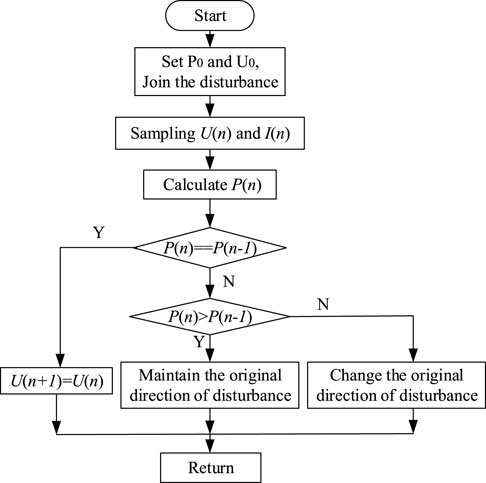
FIGURE 1. Flow chart of P&O.
The principle of P&O method is sampling the output power of the PV array at a certain working voltage, and then it increases or decreases a small voltage at the original working voltage. It samples the power after the working voltage changes, and this process can be called disturbance. The size of the power before and after disturbance is compared. If the power obtained after disturbance increases, it will continue to disturb in the original disturbance direction. If the power obtained after disturbance decreases, the direction of disturbance is opposite to the original direction. Such repeated disturbance controls the variation of working voltage for the photovoltaic array, so that its output power oscillates to reach the steady state in a small range. That means the operating point of the photovoltaic array finally stabilizes around the maximum power point. The advantages of this algorithm are simple, achievable, and it can be widely used in the maximum power point control of the photovoltaic power generation system.
PV Inverter Model
The grid-connected inverter is the core device of the photovoltaic grid-connected power generation system, which is responsible for converting the DC outputs from the photovoltaic array into AC. Considering the inverter has different loads, it can be divided into an active inverter and a passive inverter. The photovoltaic grid-connected inverter is an active inverter.
According to the characteristic of the DC side power supply, it can be divided into Voltage Source Inverter (VSI) and Current Source Inverter (CSI). The former is often used in grid-connected power generation mode, and the latter is often used in independent power generation mode.
When the pulsating waveform of the power is embodied by DC voltage, it can be called the current source inverter. The topology is shown in Figure 2A. The ideal operation mode of the inverter is maintaining the electrical power constant and no pulsation during the process of converting DC to AC, but there is power pulsation in the actual circuit.
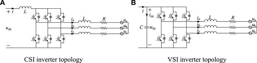
FIGURE 2. CSI and VSI inverter topology. (A) CSI inverter topology. (B) VSI inverter topology.
Under the influence of the series inductance, the front-end circuit of the inverter will present the characteristic of current source with high impedance. CSI mainly has the following characteristics:
1) When the inverter is in a huge fault state, the rising rate of the fault current can be limited by the large inductance of the CSI DC side
2) The loss of the inductance on the CSI DC side is higher than the capacitance of the VSI DC side
When the power pulsation waveform of the inverter is represented by the DC, it is called the voltage source inverter, and its topology is shown in Figure 2B. VSI connects the large capacitor in parallel in the loop, and the energy storage function of the capacitor can absorb reactive power and smooth the rectified voltage waveform. So the DC side input of the inverter can be regarded as voltage source.
Under the influence of the parallel capacitor, the front-end circuit output of the inverter has the characteristic of voltage source with low impedance. The inverter mainly has the following characteristics:
1) The loss of the capacitor generated by the VSI DC side is smaller than the inductive loss of the CSI DC side
2) The purpose of paralleling the large capacitor on the DC side of the VSI is to provide overvoltage protection to the switching device
In the process of establishing the mathematical model of the photovoltaic inverter, the high-frequency harmonic related to the switching frequency is ignored, and the mathematical model of the inverter is obtained based on the analysis of the converter fundamental wave. The model not only clearly expresses the working mechanism of the converter and the relationship between various physical quantities but also is suitable for control system analysis and the controller design. According to the topological structure diagram of the VSI grid-connected inverter in Figure 2, this article establishes the mathematical models of the three-phase inverter under grid-connected mode in the three-phase static coordinate system, the two-phase static coordinate system, and the d–q axis coordinate system, respectively. To establish the mathematical model of the inverter, some assumptions are as follows:
1) All inductors and capacitors are ideal
2) The grid electromotive force ea, eb, and ec are three-phase pure sine wave electromotive force
3) The switch tubes are all ideal, ignoring the switch dead time
4) The resistance R in the figure is the sum of the parasitic resistance of the inductor and the equivalent resistance of the fully controlled switching device
The state equation of the three-phase photovoltaic inverter in the three-phase abc stationary coordinate system can be obtained by
The simplified state equation of the three-phase photovoltaic inverter in the two-phase α-β stationary coordinate system can be obtained by
According to the instantaneous power theory, the power injected by the inverter into the grid can be calculated as
The photovoltaic cell technology guarantees the energy input of the photovoltaic grid-connected power generation system, and the grid-connected output of the system energy will be realized through the grid-connected current control strategy. The grid-connected inverter control strategy is the key technology to realize the high-performance grid-connected power generation system, which determines the energy balance and output power quality of the system. The inverter control adopts the control strategy based on the voltage orientation on the grid side, which converts each control variable to the d–q axis coordinate system to realize the decoupling control of the active power and reactive power of the inverter. At this time, eq = 0. The specific control method is using double closed-loop control scheme, which includes voltage outer loop and current inner loop.
The purpose of the voltage outer loop is to maintain the DC voltage stable, so that the electric energy generated by the photovoltaic array can stably complete the inverter process to deliver to the grid. By collecting the voltage of the DC side in real time and comparing with the reference voltage of the MPPT, the active current reference value Iderf is generated using the PI controller. The reactive current reference value Iqref is set to zero in the steady state, and the corresponding reactive current reference value is given according to the control strategy of the specific inverter during the low voltage ride-through period. The current inner loop adopts the control method of d–q axis feedforward decoupling, and realizes the decoupling control using the prepositioned PI controller. The relevant control equations are shown as follows:
In this formula, Pref and Qref are the reference power set in the system, and the photovoltaic power station is connected to the grid with the power factor one, Idref and Iqref are the active reference current and the reactive reference current, respectively, Vpv is the actual voltage effective value at the output terminal of the inverter, kp and ki are the proportional and integral gain of the PI controller, respectively.
It can be seen from the previously mentioned formulas that the active power output and reactive power output of the inverter can be controlled by adjusting id and iq.
The schematic diagram of the inverter grid-connected control system based on d–q decoupling is shown in Figure 3 and it adopts double-loop control. The inner loop is current control, and the outer loop is active power control and reactive power control.
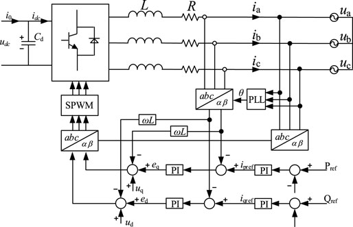
FIGURE 3. Schematic diagram of the inverter grid-connected control system based on d–q decoupling.
Detail Model of the Current Source Inverter
The current-regulated current source inverter (CR-CSI) model is a detail model of the 1 MW photovoltaic power generation system based on current source inverter. The structure diagram and inverter control strategy are shown in Figure 4 and Figure 5.
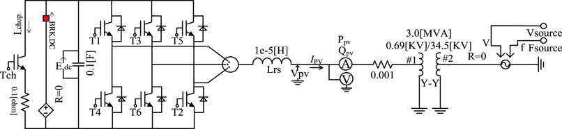
FIGURE 4. CR-CSI model based on the current source inverter.
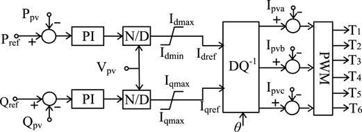
FIGURE 5. CR-CSI inverter control strategy.
As can be seen from Figure 5, the current value is compared with the PWM triangular carrier to the output current signal, which drives the IGBT to control its shutdown. In other words, the inverter output power is directly controlled by the current.
The active reference current (Idref) and reactive reference current (Iqref) expressions are
In the aforementioned formulas, Pref and Qref are the reference power set in the system, and the photovoltaic power station is connected to the grid with the power factor one. Ppv and Qpv are the actual power at the output of the inverter; Vpv is the actual voltage effective value at the output terminal of the inverter; kp and ki are the proportional and integral gain of the PI controller respectively; Idref and Iqref are the active reference current and the reactive reference current, respectively. In addition, Idmax, Idmin and Iqmax, Iqmin are the upper and lower limit of active current and reactive current, respectively; Ipva, Ipvb, and Ipvc are the actual abc three-phase current, which are outputted by the inverter; and θ is the phase angle, which phase-locked loop (PLL) tracks the grid voltage in the real time for the conversion of abc three-phase and d–q two-phase (all the values with _pu in the figures and formulas are normalized values, which will not be repeated later). Supposing Pref = 1 and Qref = 0.
Idmax, Idmin and Iqmax, Iqmin can be given by modeling parameter alone. It can only give the maximum current limit value Imax of the inverter:
Detail Model of the Voltage Source Inverter
The current-regulated voltage source inverter (CR-VSI) model is a detail model of the 1 MW photovoltaic power generation system based on the voltage source inverter. Its structural block diagram is the same as the CR-CSI model, but the signal that triggers the inverter IGBT is different, that means the inverter control strategy is different.
Normally, the output power of the photovoltaic grid-connected power generation system inverter is directly controlled by the current, and the voltage cannot directly control the power output of the inverter. The CR-VSI model uses the voltage to control current indirectly, so as to achieve the purpose which controls power output in the system.
The difference between the CR-CSI model and the CR-VSI model is shown in Figure 6. The CR-CSI model uses the difference between the reference current Is-reference and the actual measured current Is-measured to generate current signal, which can trigger the IGBT to shut down; the CR-VSI model uses the voltage feedback and the reference current Is-reference to generate voltage signal to trigger the IGBT to shut down. All in all, CR-CSI uses the reference current to generate the current signal to trigger IGBTs directly; while the CR-VSI uses the reference current to generate the voltage signal to trigger IGBTs indirectly.
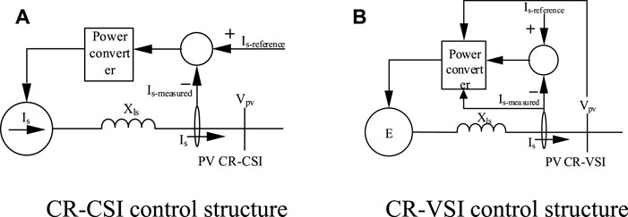
FIGURE 6. Comparison of CR-CSI and CR-VSI control structure. (A)CR-CSI control structure. (B) CR-VSI control structure.
Both the CR-CSI model and the CR-VSI model all take Vs as the input of the phase-locked loop in the inverter control link, that means it coincides with the d-axis. The decomposition of the two model system parameters in the d–q axis coordinate system is shown in Figure 7.
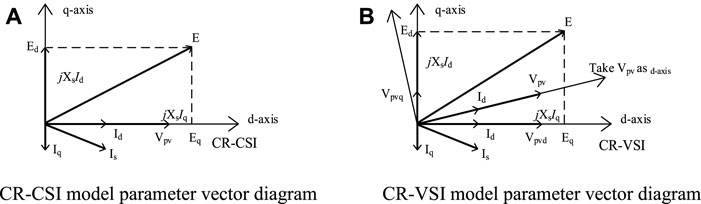
FIGURE 7. Parameter vector diagram of the CR-CSI and CR-VSI models. (A) CR-CSI model parameter vector diagram. (B)CR-VSI model parameter vector diagram
The equation which the CR-VSI model controls the output voltage E is
The voltage d–q axis separation equation is
Taking Vpv as the input of the phase-locked loop (PLL), that means it coincides with the d-axis. Vpvd = Vpv, Vpvq = 0. So, the voltage equation is transformed into
Combining Eqs 8–11, the CR-VSI inverter control strategy is shown in Figure 8.
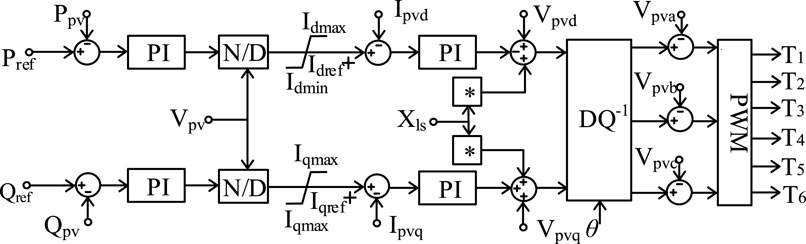
FIGURE 8. Control strategy of the CR-VSI inverter.
The aforementioned content introduces two detail models of the photovoltaic power generation system, and the CR-CSI model is common. Compared with the CR-VSI model, the CR-CSI model directly adopts current control, which can quickly provide sufficient active power and reactive power for the photovoltaic grid-connected power conversion system. The current inner loop control is realized in the d–q coordinate system. The output current of the AC side for the grid-connected inverter is converted into the DC quantities id and iq in the synchronous-rotating coordinate system through coordinate transformation, which compare with the current reference value idref and iqref delivered by the outer loop. The PI controller is used to realize the control of id and iq without static error. After the output signal of the current inner loop regulator is inversely transformed by d–q/abc, the corresponding switch drive signal of the grid-connected inverter can be obtained through sinusoidal pulse width modulation (SPWM) to realize the control of the inverter bridge.
The outer loop control is realized on the basis of the inner loop control, and the output signal of the outer loop PI controller is transmitted to the current inner loop as the current reference value idref and iqref. The control of active power is realized by controlling the d-axis current of the inverter to maintain the balance between the output power of the photovoltaic array and the output power of the inverter. The control of reactive power is realized by controlling the q-axis current of the inverter.
The Improved PV Average Model Considering High- and Low-Voltage Fault Ride-Through
The Establishment of the Photovoltaic Power Generation System Average Model
It is necessary to clarify the purpose of simulation research when simplifying the photovoltaic power generation system model, and then the corresponding model can be established. The detail models which are described earlier all have high-frequency devices, and it makes the simulation run time too long. It is not suitable for the simulation analysis of large-scale photovoltaic power plant which connects to the power system.
This section will further simplify the simulation model based on the detail model of the CR-CSI model. The three-phase controlled current source is used to replace power electronic device, which has high-frequency characteristic, and then simplified model–CSI average model is established. This model removes the IGBT switching device model and the capacitor which provides DC support in the CR-CSI model, and retains the inverter control circuit. The circuit structure and control circuit are shown in Figure 9.
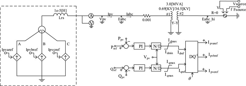
FIGURE 9. Average model.
From Figure 9, it is obvious that the average model and the CR-CSI model both directly control the output of the power converter by the current. While the difference is that the PWM generation module is ignored, Idref and Iqref are directly transformed by the dq–abc coordinate to control the average model. When the number of photovoltaic power generation units in the photovoltaic power station is large, the simulation time of the detail model will be too long. In this case, the average model can be selected to replace the detail model of the photovoltaic power station.
Modeling Considering Low-Voltage Ride-Through Control
When the point voltage of common coupling (PCC) of the photovoltaic power station drops to zero, the power station should ensure that it will not run off the grid for 0.15 s; while the PCC voltage drops to 0.2 p.u, the power station should ensure that it will not run off the grid for 0.625 s. The inverter should be able to detect the fault in time after low voltage fault occurs in the power grid, and switch the control mode from the steady state operation mode to the low voltage fault transient control mode.
When the grid falls, the inverter current will increase sharply. The power switch tube may be destroyed due to excessive current, resulting in low voltage ride-through failure. However, the traditional LVRT ability focuses on power and current quality, and there is less research on the overcurrent problem. Therefore, whether the low voltage fault transient control mode can realize the LVRT ability, the key technology is the control of the output current during the low voltage ride-through period, that means it limits the output of the active reference current and injects additional reactive current to provide enough reactive power to the system so that the terminal voltage can restore.
1) Limiting active reference current
There are two main aspects to limit the active reference current:
1) When low voltage fault occurs, the reactive power is mainly considered as the priority. So the current limit of Idmax, Idmin, and Iqmax, Iqmin is no longer applicable, and the conversion is as follows:
2) On the basis of 1), the active reference current is further reduced to obtain a new active reference current Idref_l according to the piecewise linear relationship in Figure 10. The linear shrinking relationship depends on the measured terminal voltage of the PCC, and the Idref_1 is reduced at different depths considering the voltage drop degree is different.
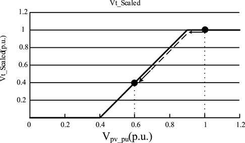
FIGURE 10. Limitation of active reference current Idref under low voltage.
In the case of low voltage, the new active reference current Idref_l is
2) Injecting reactive current
The additional reactive current Iq_l_inject is injected on the basis of outputting reactive reference current in the steady state operation mode, and the new reactive reference current Iq_ref_d is obtained.
Injecting additional reactive current Iq_d_inject:
In this formula, Vref is the reference voltage, which is taken as 1 p.u.; CLV is constant (the value ranges from zero to 10, and the empirical value is two).
In the case of low voltage, the new reactive reference current Iqref _l is
Modeling Considering High-Voltage Ride-Through Control
At present, the HVRT technology is in primary stage, and relevant standards have not been clearly defined (Wei et al., 2021; Xiao et al., 2021). According to previous researches, it finds that it is similar to the LVRT ability. When the grid-side voltage increases, the control mode is switched from the steady state operation mode to the high voltage fault transient control mode, and the output power of the photovoltaic inverter is controlled to recover voltage. The essence is also controlling the output current during high and low voltage ride-through period, and that means it limits the active current and injects additional reactive current. However, the difference from LVRT ability is the injection of reactive current. The control goal of reactive power is no longer making the inverter output enough reactive power, but making the inverter absorb reactive power from the grid. Therefore, the additional reactive current which is injected at this time is inductive reactive current, as shown in Figure 11.
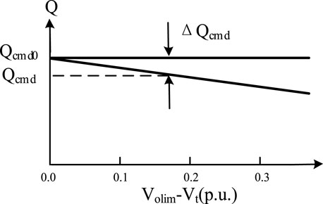
FIGURE 11. Inductive current injected under high voltage.
In the figure, Qcmd0 and Qcmd are the reactive power output in steady state operation mode and high voltage fault transient control mode, respectively; ΔQcmd is introduced inductive reactive power.
Injecting inductive reactive current Iq_h_inject:
In this formula, Volim is the threshold voltage, which is 1.1 p.u.; Chv is constant, and the specific value is determined by the local photovoltaic power generation system. If the voltage change in the local network exceeds the normal value, Chv will be adjusted accordingly. This article takes 0.7.
Then in the case of high voltage, the new reactive reference current Iqref_h is
In summary, the transient control during high and low voltage fault includes three aspects which are as follows:
1) Active power control during high- and low-voltage fault: considering reactive power is given priority to support voltage recovery during high and low voltage fault, the active power reference current depends on the voltage drop degree and the reactive reference current.
2) Reactive power control during low-voltage fault: according to the voltage drop degree, the corresponding capacitive reactive current is injected to improve the reactive power output of the inverter. Therefore, the low voltage ride-through can be realized.
3) Reactive power control during high-voltage fault: according to the degree of voltage swell, it injects corresponding inductive reactive current to make the inverter absorb the reactive power from the grid. Therefore, the high-voltage ride-through can be realized.
On the basis of the conventional PI controller, the control module which includes LVRT ability and HVRT ability is added, and it can be selectively put into operation according to the actual operating condition of the photovoltaic power generation system. Therefore, the established photovoltaic power generation system simulation model has more extensive applicability.
Case Study
Comparison of the Detail and Average Model
The average model removes the IGBT switching device model and the capacitor, which provides DC support in the detail model. Compared with the detail model, average model changes a lot. Therefore, whether the average model can accurately reflect the output characteristic of the photovoltaic grid-connected power generation system needs to be verified by simulation comparison.
The establishment of photovoltaic power generation grid-connected system model with capacity of 1 MW on the PSCAD/EMTDC software platform is taken as an example. The simulation time of both models are all 10 s, and the simulation step size is 10 μs The switching frequency of the detail model is 1,950 Hz, and the reactive power reference value in the system is 0 Mvar. When the system reaches in the steady state, it sets two situations 1) increasing the active power reference value from 1 p.u. to 1.2 p.u.; and 2) when the simulation time is 2.5 s, the voltage on the grid side will drop, and the magnitude of the drop is 28%. The duration is 3 s. According to the aforementioned content, the simulation results of the two models are compared.
From the simulation results in Figures 12–14. In terms of simulation time, the simulation running time of the detail model is 180 s, while the simulation running time of the average model is 53 s. So the average model can solve the problem that the detail model needs too long simulation time. It improves the simulation speed greatly. Even though the error of reactive power relative to active power is slightly larger in the model simulation proposed in this article, it can accurately reflect the output characteristic of the photovoltaic power plant, and retain good dynamic performance of the system. Two models have their own characteristics, and the biggest difference of them is whether they have high-frequency switching device. The detail model has high-frequency switching device, and the output of the voltage and current include the fundamental wave and harmonic, while the average model does not have high-frequency switching device, and the output only includes the fundamental wave. The effect of filter cannot be reflected. The comparison of the two models is shown in Table 1.
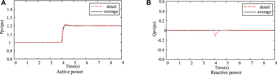
FIGURE 12. Power output of grid-connected point when active power increases. (A) Active power. (B) Reactive power.
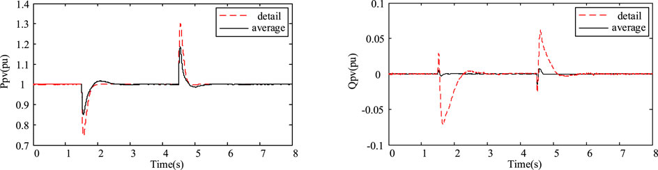
FIGURE 13. Power output of grid-connection point under voltage drop.
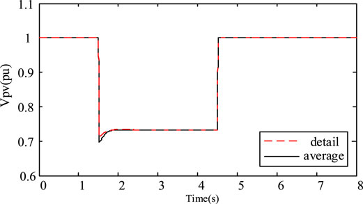
FIGURE 14. Voltage effective value of grid-connected point under voltage drop.
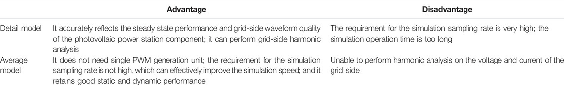
TABLE 1. Comparison of advantages and disadvantages between the detail and average models.
In summary, in view of the advantages and disadvantages of two models, different models should be selected according to the actual research purpose. The detail model is suitable for research occasion where the photovoltaic power plant has strict requirement on power quality, while the average model is more suitable for the simulation analysis of large-scale photovoltaic power plant, which is connected to the power system without special requirement for harmonic analysis.
Performance Verification Under Low-Voltage Fault
On the basis of the original PI controller of the average model, it adds a control module with LVRT ability and HVRT ability. Then, the improved control strategy is simulated and verified.
1) Low-voltage fault: it sets the reactive reference power in the system to 0 Mvar, that means the inverter works in the unit power factor state. When the system reaches in the steady state, it sets three-phase fault in the PCC point at 2 s, and clears the fault after 0.5 s.
From the simulation results in Figures 12–14, when the symmetrical three-phase short-circuit fault occurs at the PCC point, the improved average model is judged by voltage, and the circuit control mode is switched from the steady state operation model to the low voltage fault transient control mode to reduce the active power, which the photovoltaic power converter transmits to the grid. However, the reactive power will increase greatly, which supports the grid voltage effectively. In addition, the terminal voltage of the PCC point is more stable during the drop, which is conducive to the further implementation of the control strategy. When switching to the low voltage fault transient control mode, the terminal voltage of the PCC point drops to 0.6 p.u. When continuing the steady state operation mode, the terminal voltage of the PCC point drops to 0.6 p.u. This conclusion verifies that the improved control strategy has low voltage ride-through ability of the photovoltaic power generation system.
From the simulation results in Figures 15–17, when the symmetrical three-phase short-circuit fault occurs in PCC, the improved average model passes the voltage logic judgment and introduces the low voltage ride-through technology. The reactive power injected into the power grid by photovoltaic power generation will be greatly increased, and the injection of active power will be significantly reduced. The control strategy which gives priority to reactive power and limits active power can be effectively realized. According to the simulation results, the voltage at PCC terminal drops to 0.6 p.u. without considering the simulation model of low voltage ride-through ability. When the simulation model considers the low voltage ride-through ability, the PCC terminal voltage only drops to 0.69 p.u., and it can effectively support the power grid voltage.
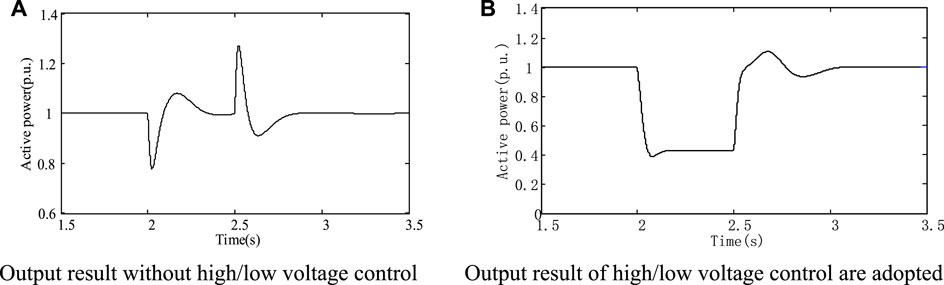
FIGURE 15. Active power output of PCC under low voltage fault. (A) Output result without high/low voltage control. (B) Output result of high/low voltage control are adopted.
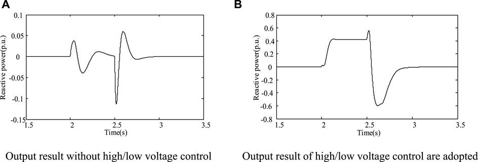
FIGURE 16. Reactive power output of PCC under low voltage fault. (A) Output result without high/low voltage control. (B) Output result of high/low voltage control is adopted.
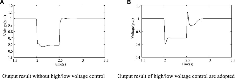
FIGURE 17. Terminal voltage output of PCC under low voltage fault. (A) Output result without high/low voltage control. (B) Output result of high/low voltage control are adopted
Performance Verification During High-Voltage Fault
The reactive reference power in the system is set to 0 Mvar, and that means the inverter works in the state of unit power factor. When the system reaches in the steady state, the voltage at the PCC point rises sharply at 2 s, and the fault is removed after 0.5 s.
When the symmetrical three-phase short-circuit fault occurs at the PCC point, the improved average model passes the voltage logic judgment, and the circuit control mode is switched from the steady state operation mode to the low voltage fault transient control mode, from the simulation results in Figures 18–20. When the terminal voltage of the PCC point swells, the improved average model passes the voltage logic judgment, and the circuit control mode is switched from the steady state operation mode to the high voltage fault transient control mode to reduce the active power, which the photovoltaic power converter transmits to the grid. It absorbs the reactive power from the distribution network and plays a supporting role on the grid voltage. In addition, when switching to the high voltage fault transient control mode, the terminal voltage of the PCC point suddenly rises to 1.114 p.u. If the steady state operation mode is continued, the terminal voltage of the PCC point drops to 1.15 p.u. This conclusion verifies that the improved control strategy has the high voltage ride-through ability of the photovoltaic power generation system.
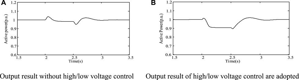
FIGURE 18. Active power output of PCC point under high voltage fault. (A) Output result without high/low voltage control. (B) Output result of high/low voltage control are adopted
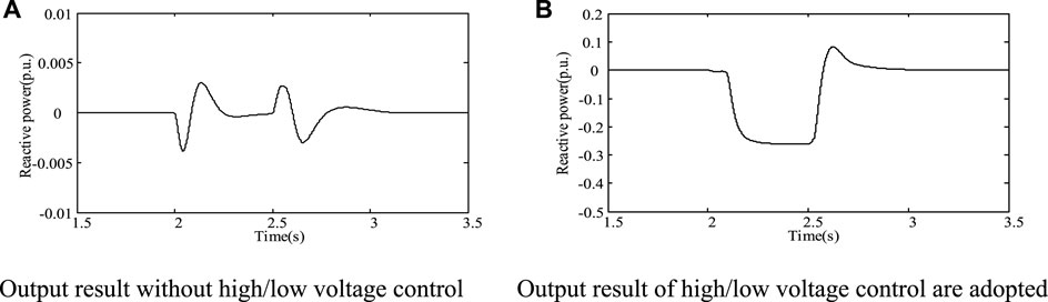
FIGURE 19. Reactive power output of PCC point under high voltage fault. (A) Output result without high/low voltage control. (B) Output result of high/low voltage control is adopted.
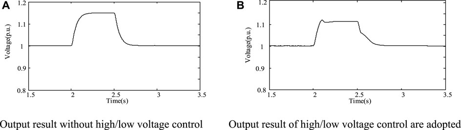
FIGURE 20. Terminal voltage output of PCC point under high voltage fault. (A) Output result without high/low voltage control. (B) Output result of high/low voltage control is adopted.
In summary, the improved average model not only shortens the simulation time greatly but also has the ability of high and low voltage ride-through, which improves the damage caused by system fault and strengthens the reliability and safety of the photovoltaic power generation system.
Conclusion
In this article, the detail models of current source inverter and voltage source inverter are established on the PACAD/ETMC software platform. Considering the detail model has power electronic device with high-frequency switching characteristic, which is not suitable for electromagnetic transient analysis of large photovoltaic power plant. To solve this problem, this study proposes a simplified model, the average model, which uses controlled current source to replace the power electronic converter device, and analyzes their respective application backgrounds, advantages, and disadvantages. Then, the control circuit of the average model is improved to switch the control mode by itself when the high- and low-voltage fault occurs in the system. Therefore, it can complete the high- and low-voltage ride-through successfully. Finally, the correctness and effectiveness of the proposed improved average model are verified by simulation.
However, with the development of photovoltaic power plant, if detail models are established for all photovoltaic power generation units in the power station to analyze grid-connected characteristic, the simulation time will be too long. The relevant research will be carried out in subsequent studies (Zhao and Liu, 2005).
Data Availability Statement
The original contributions presented in the study are included in the article/Supplementary Material; further inquiries can be directed to the corresponding author.
Author Contributions
XX and HH were responsible for the textual description. HL and WZ focused on deducing models, and JL was employed at drawing. The case study of this manuscript was conducted by NC.
Funding
This study was funded by the science and technology project of Jiangsu Electric Power Company “Research on parameter identification of renewable energy power generation model based on dynamic trajectory sensitivity and its impact on the stability of Jiangsu power grid.”
Conflict of Interest
XX, HL, WZ, and JL were employed by the Jiangsu Electric Power Company.
The remaining authors declare that the research was conducted in the absence of any commercial or financial relationships that could be construed as a potential conflict of interest.
Publisher’s Note
All claims expressed in this article are solely those of the authors and do not necessarily represent those of their affiliated organizations, or those of the publisher, the editors, and the reviewers. Any product that may be evaluated in this article, or claim that may be made by its manufacturer, is not guaranteed or endorsed by the publisher.
References
De Soto, W. (2004). Improvement and Validation of a Model for Photovoltaic Array Performance[D ]. Madison: University of Wisconsin-Madison.
El Moursi, M. S., Xiao, W., and Kirtley, J. L. (2013). Fault Ride through Capability for Grid Interfacing Large Scale PV Power Plants. IET Gener. Transm. & Distrib. 7 (9), 1027–1036. doi:10.1049/iet-gtd.2013.0154
Elkayam, M., and Kuperman, A. (2019). Optimized Design of Multiresonant AC Current Regulators for Single-phase Grid-Connected Photovoltaic Inverters. IEEE J. Photovoltaics 9 (6), 1815–1818. doi:10.1109/jphotov.2019.2937386
Gaikwad, A. M., and Mittal, S. K. (2020). A Single-phase Transformer-Less Grid Connected Photovoltaic Inverter. Proceeding of the 2020 Fourth International Conference on Inventive Systems and Control (ICISC). Coimbatore, India, 8-10 January 2020. IEEE, 619–625. doi:10.1109/icisc47916.2020.9171090
Gow, J. A., and Manning, C. D. (1999). Development of a Photovoltaic Array Model for Use in Power-Electronics Simulation Studies. IEE Proc. Electr. Power Appl. 146 (2), 193–200. doi:10.1049/ip-epa:19990116
He, Y., and Hu, J. (2012). Several Hot Issues in Grid Connected Operation of Doubly Fed Asynchronous Wind Turbine[J]. Chin. J. Electr. Eng. 32 (27), 1–15.
Kawabe, K., and Tanaka, K. (2015). Impact of Dynamic Behavior of Photovoltaic Power Generation Systems on Short-Term Voltage Stability. IEEE Trans. Power Syst. 30 (6), 3416–3424. doi:10.1109/tpwrs.2015.2390649
Kim, S.-K., Jeon, J.-H., Cho, C.-H., Kim, E.-S., and Ahn, J.-B. (2009). Modeling and Simulation of a Grid-Connected PV Generation System for Electromagnetic Transient Analysis. Sol. Energy 83 (5), 664–678. doi:10.1016/j.solener.2008.10.020
Liu, Y., Zhao, D., Zhang, L., Chen, N., and Zhu, L. (2015). Modeling and Simulation of the Solar Photovoltaic Systems for Grid Studies Considering the Negative Sequence Control Strategy[C], Proceeding of the International Conference on Renewable Power Generation (RPG 2015). Oct. 2015, Beijing. IET.
Mirhosseini, M., Pou, J., and Agelidis, V. G. (2015). Single- and Two-Stage Inverter-Based Grid-Connected Photovoltaic Power Plants with Ride-Through Capability under Grid Faults. IEEE Trans. Sustain. Energy 6 (3), 1150–1159. doi:10.1109/tste.2014.2347044
Mohseni, M., and Islam, S. M. (2012). Transient Control of DFIG-Based Wind Power Plants in Compliance with the Australian Grid Code. IEEE Trans. Power Electron. 27 (6), 2813–2824. doi:10.1109/tpel.2011.2174380
Nanou, S. I., and Papathanassiou, S. A. (2014). Modeling of a PV System with Grid Code Compatibility. Electr. Power Syst. Res. 116 (11), 301–310. doi:10.1016/j.epsr.2014.06.021
Sosa, J. L., Castilla, M., Miret, J., Matas, J., and Al-Turki, Y. A. (2016). Control Strategy to Maximize the Power Capability of PV Three-phase Inverters during Voltage Sags. IEEE Trans. Power Electron. 31 (4), 3314–3323. doi:10.1109/tpel.2015.2451674
Su, J., Yu, S., Zhao, W., Wu, M., Shen, Y., and He, H. (2001). Mathematical Model for Silicon Solar Cell Engineering[J]. Electr. Power Appl. 22 (4), 409–412. doi:10.3321/j.issn.0254-0096.2001.04.009
Wei, C., Zhao, Y., Zheng, Y., Xie, L., and Smedley, K. M. (2021). Analysis and Design of a Non-isolated High Step-Down Converter with Coupled Inductor and ZVS Operation[J]. IEEE Trans. Industrial Electron. 69, 9007-9018. doi:10.1109/tie.2021.3114721
Xiao, D., Chen, H., Wei, C., and Bai, X. (2021). Statistical Measure for Risk-Seeking Stochastic Wind Power Offering Strategies in Electricity Markets[J]. J. Mod. Power Syst. Clean Energy.2021, 1-6. doi:10.35833/MPCE.2021.000218
Xie, Z., Zhang, X., Song, H., Yang, S., and Cao, R. (2012a). Variable Damping Control Strategy of Doubly Fed Wind Turbine under Power Grid Voltage Surge Fault. J. Power Syst. Autom. 36 (3), 39–46. doi:10.3969/j.issn.1000-1026.2012.03.007
Xie, Z., Zhang, X., Yang, S., Song, H., Qu, T., et al. (2012b). High Voltage Ride through Control Strategy of Doubly Fed Wind Turbine Based on Virtual Impedance. Chin. J. Electr. Eng. 32 (27), 16–23. doi:10.13334/j.0258-8013.pcsee.2012.27.003
Zhang, M., and Chen, X. (2014). Low Voltage Ride through Control Strategy of Photovoltaic Grid Connected Power Generation System. Power Syst. Prot. control 42 (11), 28–33. doi:10.7667/j.issn.1674-3415.2014.11.005
Zhang, Y., Zheng, Q., Ma, L., and Lu, Y. (2013). Mathematical Model for Silicon Solar Cell Engineering. [J] J. Electrotech. 28 (12), 136–141. doi:10.19595/j.cnki.1000-6753.tces.2013.12.019
Zhao, Z., and Liu, J. (2005). Solar Photovoltaic Power Generation and its application[M]. Beijing: Science and Technology Press.
Zhou, C., Jiang, H., and Xie, F. (2019). Research on the Control of Three-Level Photovoltaic Grid-Connected Inverter Based on NPC. Proceeding of the 2019 14th IEEE Conference on Industrial Electronics and Applications (ICIEA). Xi'an, China, 19-21 June 2019. IEEE, 1327–1331. doi:10.1109/iciea.2019.8834360
Keywords: photovoltaic, power generation, voltage, fault ride-through, modeling
Citation: Xu X, Han H, LI H, Zhou W, Li J and Chen N (2022) Modeling of Photovoltaic Power Generation Systems Considering High- and Low-Voltage Fault Ride-Through. Front. Energy Res. 10:935156. doi: 10.3389/fenrg.2022.935156
Received: 03 May 2022; Accepted: 17 May 2022;
Published: 23 June 2022.
Edited by:
Dongliang Xiao, South China University of Technology, ChinaReviewed by:
Jianwu Zeng, Minnesota State University, Mankato, United StatesXuemei Dai, Shanghai University of Electric Power, China
Copyright © 2022 Xu, Han, LI, Zhou, Li and Chen. This is an open-access article distributed under the terms of the Creative Commons Attribution License (CC BY). The use, distribution or reproduction in other forums is permitted, provided the original author(s) and the copyright owner(s) are credited and that the original publication in this journal is cited, in accordance with accepted academic practice. No use, distribution or reproduction is permitted which does not comply with these terms.
*Correspondence: Hualing Han, aGFuaHVhbGluZ0BlcHJpLnNnY2MuY29tLmNu