 Yuxiang Li
 Yan Wu
 Xuewu Cao*
95% of researchers rate our articles as excellent or good
Learn more about the work of our research integrity team to safeguard the quality of each article we publish.
Find out more
ORIGINAL RESEARCH article
Front. Energy Res. , 12 July 2022
Sec. Nuclear Energy
Volume 10 - 2022 | https://doi.org/10.3389/fenrg.2022.927497
This article is part of the Research Topic Experimental and Analytical Investigations on Nuclear Reactor Safety, Severe Accident Phenomena and Severe Accident Mitigation of Nuclear Power Plants View all 20 articles
In severe nuclear power plant accidents, when the containment is in a serious challenging state, the gas mixture in the containment can be injected into the spent fuel pool through the multihole injector by the containment depressurization measure, to reduce the risk of containment overpressure failure and the release of radioactivity to the environment. The pool scrubbing efficiency of aerosol under the jet regime is studied on the small-scale aerosol pool scrubbing facility, focusing on the influence of mass flux, steam fraction, submergence, particle diameter, and pool initial temperature on the aerosol decontamination factor (DF). The results show that under the jet regime, the DF value is significantly greater than that in the bubble regime and the effect of jet flow on the mechanism of steam condensation and aerosol removal of the rising zone is weak under the conditions explored. DF increases with the increase of mass flux owing to the droplet interception and inertial collision aerosol removal mechanisms. Because the high pool temperature weakens the aerosol removal by steam condensation, DF decreases with the increase of initial pool temperature under the conditions explored. Based on the experimental data and the analysis of the removal mechanism under the jet regime, an empirical model of aerosol DF considering mass flux, steam fraction, pool temperature, submergence, and particle size is established and verified by the international experiments. The proposed model can be used to calculate DF in the process of containment overpressure discharge.
For the Chinese Advanced Passive Pressurized Water Reactor, containment overpressure venting is activated when the containment pressure continues to rise owing to the failure of the PCCS and other pressure relief measures in severe accidents. The gas mixture containing aerosols from containment is planned to be discharged into the spent fuel pool (SPF) through the multihole injector to reduce the risk of radioactive release to the environment (Gao et al., 2017; Gao et al., 2022). In the process of containment overpressure venting, the steam volume fraction gas exceeds 90%, the discharge mass flow rate can reach 7 kg/s, and the injector has 300 holes with a diameter of 1 cm (Gao et al., 2017). In this case, the aerosol-laden gas mixture is injected into the pool in the form of a jet regime at high speed and hits the water body to produce broken droplets, which are entrained in the gas and collide with the aerosol particles so that the aerosol is retained in the pool.
Lebel et al. (2022) conducted a review of different pool scrubbing experiments in 2022. A summary of the experimental study of pool scrubbing under the jet regime is given in Table 1. The LACE-Espana project was completed by Centro de Investigaciones Energéticas MedioAmbientales y Tecnológicas (CIEMAT) (Marcos et al., 1994). The main objectives were to analyze the pool scrubbing dependence on steam mass fraction and particle diameter under a single-hole injector and the bubble regime. Just two experiments were in the jet regime, but the steam mass fraction is only 0.1, and the retention capacity is slightly enhanced. In 1995, RCA experiments were also conducted by CIEMAT (Peyres et al., 1995), and the effect of different submerged depths (0.25–2.5 m) on pool scrubbing under the jet regime was studied. The POSEIDON-II program carried out 17 experiments at the Paul Scherrer Institute (PSI) (Dehbi et al., 1997; Dehbi et al., 2001). They analyzed pool scrubbing dependence on steam mass fraction (0–72%), mass flow rate (87–153 kg/h), submergence (0.3–4 m), and pool temperature (80°C–94°C) under a single-hole injector. In 2011, a continuation project ARTIST-II was initiated to address issues raised in the aerosol trapping in the steam generator (ARTIST) project by PSI (Lind et al., 2011). The effect of pool scrubbing under two different mass fluxes (63 and 780 kg/m2s) and particle sizes in four sets of experiments with nitrogen as the carrier gas was investigated. The RSE experiments were completed within the framework of the EU-PASSAM project of Italy to study the effect of pool scrubbing in natural water and seawater and in the presence of additives under the air jet regime (Albiol et al., 2018; Herranz et al., 2018b). PSP experiments were carried out by CIEMAT within the framework of the EU-PASSAM project (Herranz et al., 2018a) to study the effect of pool scrubbing under a single-hole injector at steam mass fraction lower than 10% and mass fluxes in the range of 74–152 kg/m2s. In recent years, more and more institutions have also paid attention to the pool scrubbing process again. Sun et al. (2019) studied the dependence of decontamination factor (DF) on aerosol concentration in pool scrubbing with a single-hole injector. The results showed that DF increased monotonically with decreasing particle number concentration, but the correlation was weak when the particle concentration is greater than 1011 P/m3 in the water submergence higher than 1.6 m. Diao et al. (2020) conducted HARBIN experiments, which mainly studied the effect of nozzle inlet pressure and gas injection direction on noncondensing gas jet flow, showing that the aerosol removal efficiency increases as the inlet pressure increases (from 0.12 to 0.4 MPa). The SAAB experiments were carried out at Research Center Juelich. This is a large-scale facility with the ability to perform a great variation of experiments, and the first test series with soluble particles including cesium iodide (CsI) had been reported by Vennemann et al. (2022).
TABLE 1. Summary of experimental study of pool scrubbing under the jet injection regime.
Most of the earlier experiments on aerosol pool scrubbing were carried out under the conditions of low mass flow rate and single-hole injector. In contrast, the research on aerosol pool scrubbing in the jet regime was carried out only under the conditions of lower steam fraction shown in Table 1, which failed to reflect the high steam fraction characteristics of the gas mixture discharged from the containment and the multihole structure of the discharge device. Therefore, the effects of steam fraction, pool depth, mass flux, and pool temperature on the pool scrubbing effect under the multihole and jet regime should be investigated.
For the model of pool scrubbing DF, Wassel et al. (1985) introduced the aerosol scrubbing model, which has been the basis of several pool scrubbing analysis codes, such as SUPRA, BUSCA, and SPARC codes (Owczarski et al., 1985). However, because of droplet–particle interaction in the jet region, these tools are not suitable for high-velocity conditions. Berna et al. (2016) introduced the collision interception between aerosol particles and droplets generated by gas impact in the case of noncondensable gas jet injection, and the SPARC90-Jet code is developed, which enhanced the simulation of pool scrubbing in the jet regime of noncondensable gas. Yan et al. (2020) considered the deposition mechanism from fluctuation interface and entrainment droplets simultaneously, improving the simulation of pool scrubbing under the jet regime of noncondensable gas.
In this paper, an empirical model of aerosol DF is proposed considering mass flux, steam fraction, pool temperature, submergence, and particle size based on the experimental data and the mechanisms of interception and inertial impact in the jet regime and is validated by other tests.
The experiment was carried out at a small-scale aerosol pool scrubbing facility (SAPOS) (Li et al., 2021), mainly including a test vessel, a gas supply system, a data acquisition system, aerosol supply, and measurement systems (Figure 1). The test vessel is a vertical cylinder with upper and lower ellipsoidal heads, 5.0 m in height and 1.0 m in diameter. The gas supply system mainly includes the air compressor, steam generator, and nitrogen cylinder. The air compressor can provide a maximum mass flow rate of 90 kg/h, the steam generator can provide 150 kg/h, and the nitrogen is mainly used for the aerosol generator with a maximum flow rate of 40 kg/h. Electric heat tracing is arranged on the steam and air pipe to prevent steam condensation. The titanium dioxide (TiO2) aerosols are generated using pure nitrogen as the carrier gas. Pressures, temperatures in the pipe and vessel, and fluid mass flow rates are measured and collected using the data acquisition system.
FIGURE 1. Schematic of small-scale aerosol pool scrubbing facility.
The study focuses on the influence of thermal parameters on the effect of aerosol scrubbing pool with the typical structure of a multihole injector. Two downward vertical injectors with different apertures of the injector are used with the hole diameters (D0) of 1 and 0.5 cm. Both injectors have six holes and are divided on either side of the injector. The bottom of the multihole injector is 50 cm above the bottom of the vessel.
As shown in Figure 2, the aerosol concentration measurement system comprises a thin-wall sampling nozzle, temperature control system, aerosol spectrometer system, filter membrane (>0.1 μm), flow meter, regulating valve, and heat exchanger. The inner diameter of the thin-wall sampling nozzle is 2.6 and 5.0 mm at the inlet and outlet pipes, respectively. Figure 3 shows the aerosol particle size distribution at a mass median diameter (MMD) of 0.5 μm, which is an approximately standard normal distribution with a geometric standard deviation (GSD) of 1.26. Table 2 shows the experimental parameters and their ranges. The experiments were performed while changing only one parameter to clarify the influence of other parameters.
FIGURE 2. Schematic of the aerosol concentration measurement system.
FIGURE 3. Aerosol size distribution of TiO2 with mass median diameter 0.50 μm.
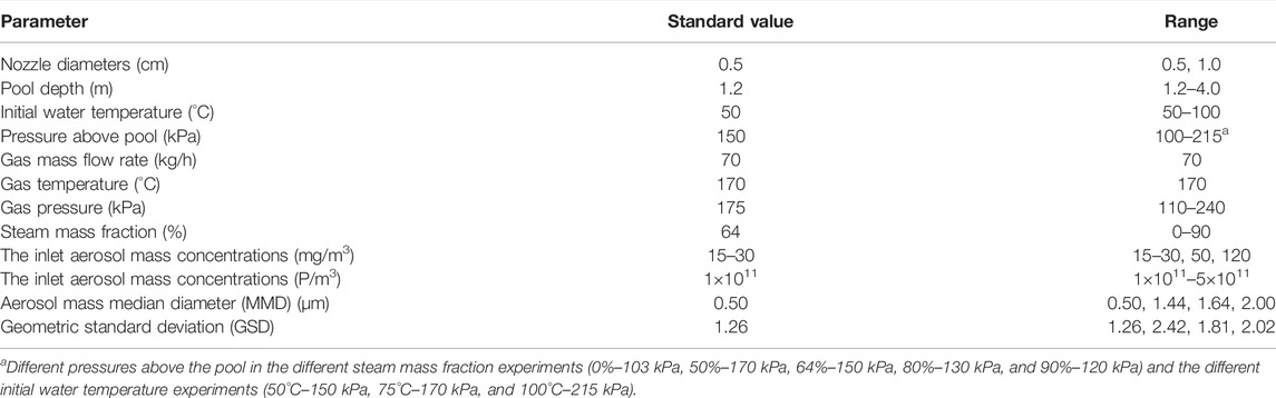
TABLE 2. Small-scale aerosol pool scrubbing experimental test conditions.
The DF is defined as the ratio of the inlet aerosol mass flow rate to the outlet aerosol mass flow rate, as shown in Eq. 1:
where Wa-in and Wa-out are the aerosol mass flow rates in and out of the test vessel, respectively, mg/s; Cm-in and Cm-out denote the inlet and outlet aerosol mass concentrations, respectively (mg/m3); and Qin and Qout represent the inlet and outlet volume flow rates, respectively, m3/s.
Aerosol concentration is affected by many factors, mainly including aspiration efficiency, aerosol deposition in the sampling pipe, and the measurement error of the aerosol particle size spectrometer. The efficiency of making a particle enter the sampling pipe is called aspiration efficiency. The thin-wall sampling nozzle and coaxial sampling method are used in this experiment, as shown in Figure 2, and the aspiration efficiency can be calculated using Eqs 2 and 3 (Liu et al., 1989; Zhang and Liu, 1989). The flow velocity at the inlet pipe and the Stk number at the sampling nozzle is in the range of 4–20 m/s and 0.01–0.4, respectively, and the sampling velocity is 15.7 m/s. The flow velocity at the outlet pipe is in the range of 4–13 m/s, the Stk number is lower than 0.02, and the sampling velocity is 4.3 m/s. Therefore, the aspiration efficiency of the inlet and outlet ranges from 0.95 to 1.05.
where ηasp is the aspiration efficiency; U0 is the ambient gas stream velocity, m/s; U is the sampling velocity, m/s; Stk is the dimensionless stokes number; ρp is the particle density, kg/m3; dp is the particle diameter, m; μ is the dynamic viscosity of ambient gas steam, Pa·s; D is the nozzle diameter of sampling pipe, m.
Aerosol deposition in a pipe is mainly caused by the inertial collision in the bend pipe, and the deposition velocity is written as Eq. 4 (Chatzidakis, 2018). Moreover, the fractional penetration is calculated by using Eq. 5 (Sehmel, 1968; Benjamin and Jugal, 1974). The Stk numbers of the inlet and outlet sampling pipeline range from 0.003 to 0.1, and the penetration rate of the sampling pipeline is greater than 95%.
where Vi is the deposition velocity, m/s; Ps is the fractional penetration through the bend pipe; Lc is the elbow arc length, m; Qs is the volume flow rate of sampling, m3/s; and d0 is the diameter of sampling pipe, m.
The maximum deviation of the aerosol concentration measurement system is 20% after calibration using the filter sampling method with different aerosol concentrations, which considers aspiration efficiency, aerosol deposition in the sampling pipe, and the measurement error of the aerosol particle size spectrometer. The volume flow at the inlet and outlet can be calculated using the ideal gas equation of Q =WRT/Mp, where Q is the volume flow rate of the carrier gas, m3/s; W is the mass flow rate of the carrier gas measured by the flowmeter with an accuracy of 1%, g/s; T and p denote the temperature and pressure of the carrier gas measured using the sensor with an error of ±1 K and ±1.0% full scale, respectively, K and Pa; M is the molecular weight, g/mol; and R is an ideal gas constant, 8.314 J/(mol·K).
The error transfer formula proposed by Kline and McClintock (1953) is used to estimate the error of indirect measurement parameters, shown as Eq. 6. The detailed relative error calculation for the DF is expressed in Eqs 7 and 8, and the maximum error is 29%.
where Y is calculated from the measured quantities x1, x2, ..., xn with errors σx1, σx2, ..., σxn. In this study, the measured quantities mainly include Cm-in, Cm-out, W, T, and p, and the indirect calculations include DF and Q.
According to the different characteristics of gas–liquid hydrodynamic behavior, the pool scrubbing process can be divided into two central regions, as shown in Figure 4, including injection and rise zone. The injection zone is characterized by the formation of the unstable vapor globule or jet column, which subsequently breaks up into bubble swarm. At last, the bubble swarm quickly rises to the surface of the pool and escapes in a very short period time.

FIGURE 4. Schematic diagram of the pool scrubbing process.
In the injection zone, with the flow rate increase, the gas injection form changes from bubble to jet regime. To study the effect of different flow regimes on aerosol DFs, experiments are carried out with different injectors with hole diameters of 1 and 0.5 cm under the same gas mass flow rate (70 kg/h). The flow regime at a mass flux of 41 kg/m2s is given in Figure 5, indicating that large unstable bubbles are generated and gradually broken up into small bubbles, and finally rise to the pool surface, which is a typical bubble flow regime. The flow regime at a mass flux of 164 kg/m2s is given in Figure 6, indicating that the gas core flows along the horizontal jet direction, and the size of gas core continues to increase away from the nozzle. At the end of the horizontal gas core, numerous small bubbles disperse and move upwards gradually under the action of buoyancy.
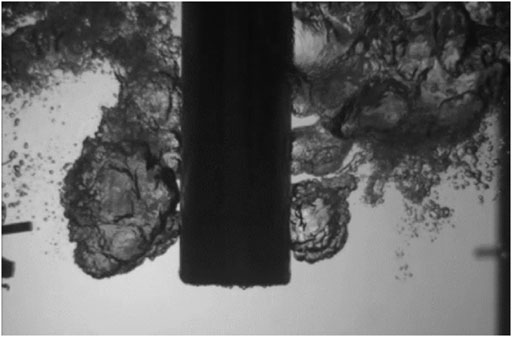
FIGURE 5. Bubble flow image at 41 kg/m2 s (D0=1 cm, Xm=0.64).
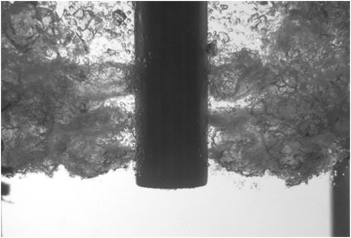
FIGURE 6. Jet flow image at 164 kg/m2 s (D0=0.5 cm, Xm=0.64).
The DFs versus different steam mass fractions at flow regimes are shown in Figure 7. The higher steam fraction results in an enhanced of steam condensation mechanism, and an increased aerosol retention effect. The steam condensation mechanism can be described as Eq. 9 (Owczarski and Burk, 1991), ln(S) and ln(DF) show a linear relationship as shown in Figure 8. Their growth slopes are almost the same in the two different flow regimes, but the DF value is significantly higher in the jet regime.
where S is the fractional loss in gas volume caused by condensation; Xs is the mole fraction of steam in inlet gas mixture; Xs,eq is the mole fraction of steam after it attains thermal and steam equilibrium in the pool at the inlet depth. ps is the saturated steam pressure at pool temperature, Pa; p0 is the pressure above the pool, Pa; ρl is the density of pool water, kg/m3; H is submerged depth, m. Condensation will occur if 1-Xs,eq is greater than 1-Xs, otherwise evaporation will occur and this retard particle motion toward the interface. For 1-Xs,eq<1-Xs, it is assumed that DF = 1.
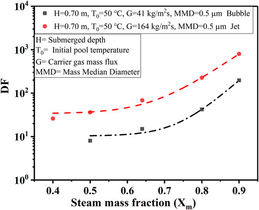
FIGURE 7. Steam mass fraction effect on decontamination factor (DF).
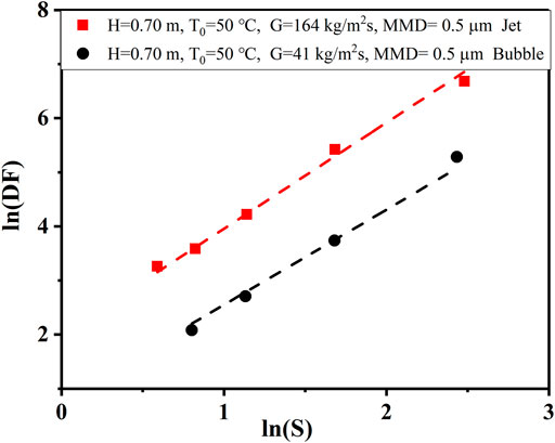
FIGURE 8. Correlation between ln(DF) and ln(S) under different flow regimes.
Figure 9 shows the DFs of different flow regimes at different submerged depths. DF increases exponentially with the increase of submergence depth. The increase in submerged depth leads to an increase in the rising distance of bubbles, making the action time of the aerosol removal mechanism (gravity deposition, centrifugal deposition, Brownian diffusion) longer, which also makes the aerosol removal more efficient. The same growth trend of DF at different flow regimes indicates that jet flow mainly affects aerosol retention at the injection region. At the same time, Figures 8 and 9 also illustrates that jet regime contributes to the aerosol retention in pool within the range of experimental conditions.
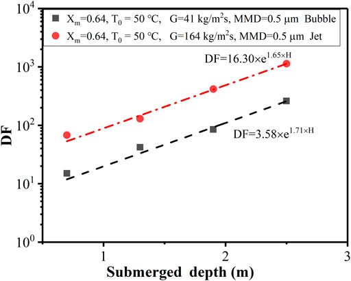
FIGURE 9. Effect of submerged depth on DF.
The effect of different mass fluxes on DF under the jet regime is studied with pure air as the carrier gas. According to the dimensionless Weber number (We), the inlet gas regime is judged as the jet regime (We ≥ 105) and the bubble regime (We < 105) (Herranz et al., 2018b). The mass fluxes range from 50 to 170 kg/m2s, and We as shown in Eq. 10 ranges from 105 to 106 in this experiment.
where ρl is the density of pool water, kg/m3; Dinj is the hole diameter of the injector, m; vinj is the gas velocity at the outlet, m/s; and σ is the surface tension of pool liquid, N·m.
Figure 10 shows that the mass flux greatly influences the retention of aerosols in the pool, and DF increases approximately linearly with the increase of mass flux. Figure 11 also implies that DF increases with the increase of injection mass flux and particle size with the same steam mass fraction of 64%. This is mainly because, in the injection zone, the high-speed gas interacts with the water and causes water entrainment in the form of droplets. Then the aerosol is removed by droplet interception, inertial collision, and diffusion. As the jet mass flux increases, the jet length and entrained droplet fraction increase, as shown in Eqs 11 and 12 (Berna et al., 2016). Therefore, the droplet interception and inertial collision effects are enhanced, resulting in an increase in DF.
where L is the length of the jet, m; Do is the pore size of the injector, m; u0 is the velocity of gas, m/s; ρg is the density of gas, kg/m3; ρl is the density of pool water, kg/m3; μg is the dynamic viscosity of gas, Pa·s; μl is the dynamic viscosity of liquid, Pa·s; Weg is the Weber number of gas; Reg is the Reynold number of gas; Rel is the Reynold number of liquid; E is the entrained droplet fraction; and cw is a factor used to illustrate the effect of surface tension.
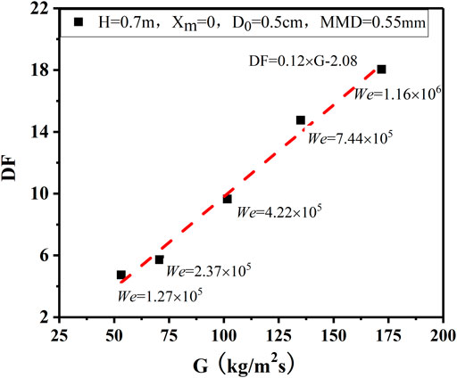
FIGURE 10. Influence of mass flux on DF with incondensable gas under the jet regime.
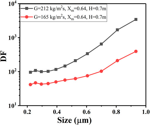
FIGURE 11. Influence of mass flux on DF with the presence of steam under the jet regime.
Experiments on three pool initial temperatures with 50°C, 73°C, and 97°C are carried out to reveal the influence of pool temperature on DF. The DF decreases with the initial temperature increase, shown in Figure 12. The main reason is that as the pool temperature increases, the mole fraction of steam after it attains thermal and steam equilibrium in the pool at the inlet depth is higher. As a result, the steam condensation is weakened, which can be described as Eq. 9. At the same time, the increase in pool temperature accelerates the rise of stable bubbles, which is also unfavorable to the aerosol scrubbing.
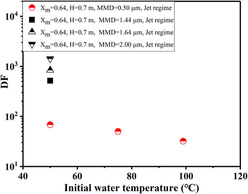
FIGURE 12. Effect of initial pool temperature and particle diameter on DF.
Figure 12 also shows the DFs of different particle mass median diameters (0.50, 1.44, 1.64, and 2.00 μm). It is expected that DF strongly depends on the particle diameter and shows an order of magnitude increase with the particle diameter due to inertial impaction, gravity settling, and Brownian diffusion during the injection and rise regions. It can also be seen from Figure 11 that the DF hardly changes for a particle diameter smaller than 0.50 μm, while for a particle diameter greater than 0.50 μm, the DF increases rapidly. This reveals that the influence of inertial impaction on the DF is dominant for large particles.
In the case of the jet regime, the gas can enter the pool through an injector and form a jet column at the outlet due to high flow velocity, followed by the rupture of the column to form small bubbles that rise rapidly to the surface of the pool and eventually escape. The following describes the establishment of empirical equations for DF calculation under the jet regime.
In the injection zone, the form of gas–liquid interaction affects the process of pool scrubbing, where the gas injection velocity and composition are key variables. When the injection zone is in the jet regime, steam condenses at the injector outlet at first, and ln(DF) is proportional to ln(S), as shown in Figure 8. Then the remaining gas interacts with water, and a fraction of the liquid film contacting the gas can enter the gas core in the form of droplets, which capture the aerosol particles. At this point, the main removal mechanisms include droplet interception and inertial impaction. This is mainly related to droplet diameter, gas velocity, and particle size, among which droplet diameter and gas velocity are affected by the mass flux of the remaining gas (Gn). It can be seen from Figure 10 that DF is in a linear relationship with G. DF is approximately proportional to the square of the particle diameter by nonlinear fitting of the experimental data in Figure 12. Therefore, the DF value in the injection region is simplified into Eq. 13.
where DFin is the DF value in the injection region; Gn is the mass flux of the uncondensed gas, Gn = G(1−Xm)/(1−Xm,eq), Xm,eq is the mass fraction of steam after it attains thermal and steam equilibriumin the pool at the inlet depth. dp is the aerosol particle diameter, m; and n, A, and B are constants.
In the rise zone, the aerosol is gradually transferred from the bubble to the water due to gravity settling, centrifugal deposition, and Brownian diffusion, shown in Table 3 (Owczarski et al., 1985; Li et al., 2020). The DF of the rise zone for pool scrubbing is expressed as Eq. 14.
where λ is the retention efficiency coefficient of particles in the bubble, s−1; vsw is the average rising velocity of the bubble group, m/s; VB is the stable bubble volume, m3; and A is the bubble surface area for particle deposition, m2.
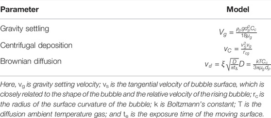
TABLE 3. Aerosol deposition velocity in the rise zone.
The bubble diameter and its rising velocity are assumed to be constant. Eq. 14 can be simplified as a function of the particle diameter (m) and the submerged depth (m), shown as Eq. 15, where C and D are constants.
The product of DFs calculated by different mechanisms is the final cumulative DF. Therefore, the overall DF may be written as DF = DFin × DFrise as Eq. 16.
The best fit of all these experiment data used is achieved by the following Eq. 17 under the conditions explored. Moreover, this correlation should only be used for multihole injector systems in an open pool with steam mass fractions from 0 to 90%, particle diameters from 0.2 to 2 μm, submerged depths from 0.7 to 2.5 m, and Gn from 20 to 212 kg/m2s.
The proposed empirical model is validated with the RAC, ACE, ARTIST, and RSE experimental data, shown in Figure 13. To evaluate the effectiveness of the empirical model quantitatively, the under-prediction factor (UF) is adopted, defined as Eq. 18 (Humphries et al., 2015; He et al., 2021). The UF in the range of 0.1–10 is usually considered acceptable. The closer the UF is to 1, the better the consistency containment.
where MD is the mean difference of DF, DFm is the experimental DF, and DFc is the calculated DF.
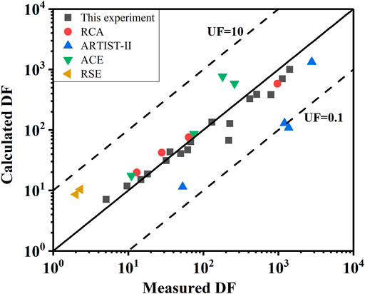
FIGURE 13. Comparison between the calculated DF and the experimental data.
The predicted DF result is in good agreement with the experimental result with the UF in the range of 0.1–10, except ARTIST. The calculated DF of ARTIST text has a large discrepancy from the experimental values owing to the complex geometry (tube bundle) in the steam generator tube rupture accident. Further study will be to expand the test mass flux to extend the applicability of the empirical model. In summary, this empirical model can be used to calculate the DF during containment overpressure discharge.
A study of the aerosol retention efficiency under jet regime conditions was carried out at the SAPOS facility. The flow regime gradually changes from bubble regime to jet regime With the increase of mass flux. When the carrier gas is a non-condensing gas, the flow regime is judged as the jet regime (We ≥ 105) and the bubble regime (We < 105). When the carrier gas contains steam, the flow regime at the two mass fluxes of 41 and 164 kg/m2s are bubble and jet regimes, respectively. With the increase of steam fraction and submerged depth, the trend of DF growth is approximately the same under different flow regimes, but the DF value is significantly higher in the jet regime in the conditions explored. The influence of mass flux and pool initial temperature on the DF is also investigated, and the results show that the DF increases with increasing mass flux due to the enhanced droplet interception and inertial collision aerosol removal mechanism, and because the high-water temperature weakens the aerosol removal by steam condensation, DF decreases with the increase of initial pool temperature.
In addition, an empirical model of aerosol DF considering mass flux, steam fraction, pool temperature, submerged depth, and particle size is established for the jet regime and verified by the international experiments under the conditions explored. The proposed model can be used to calculate DF in the process of containment overpressure discharge.
The original contributions presented in the study are included in the article/Supplementary Material, and further inquiries can be directed to the corresponding author.
YL: performed the experiment, formal analysis, writing—original and draft. YW: methodology, investigation, writing—review and editing, and supervision. XC: conceptualization, methodology, and supervision.
The authors declare that the research was conducted in the absence of any commercial or financial relationships that could be construed as a potential conflict of interest.
All claims expressed in this article are solely those of the authors and do not necessarily represent those of their affiliated organizations, or those of the publisher, the editors, and the reviewers. Any product that may be evaluated in this article, or claim that may be made by its manufacturer, is not guaranteed or endorsed by the publisher.
Albiol, T., Herranz, L., Riera, E., Dalibart, C., Lind, T., Del Corno, A., et al. (2018). Main Results of the European PASSAM Project on Severe Accident Source Term Mitigation. Ann. Nucl. Energy 116, 42–56. doi:10.1016/j.anucene.2018.02.024
Benjamin, Y. H. L., and Jugal, K. A. (1974). Experimental Observation of Aerosol Deposition in Turbulent Flow. J. Aerosol. Sci. 5, 148–155. doi:10.1016/0021-8502(74)90046-9
Berna, C., Escrivá, A., Muñoz-Cobo, J. L., and Herranz, L. E. (2016). Enhancement of the SPARC90 Code to Pool Scrubbing Events under Jet Injection Regime. Nucl. Eng. Des. 300, 563–577. doi:10.1016/j.nucengdes.2016.02.027
Berna, C., Escrivá, A., Muñoz-Cobo, J. L., and Herranz, L. E. (2015). Review of Droplet Entrainment in Annular Flow: Characterization of the Entrained Droplets. Prog. Nucl. Energy 79, 64–86. doi:10.1016/j.pnucene.2014.11.011
Chatzidakis, S. (2018). SCC Aerosol Transport Model Summary Report. United States: Oak Ridge National Lab. doi:10.2172/1492159
Dehbi, A., Suckow, D., and Guentay, S. (2001). Aerosol Retention in Low-Subcooling Pools under Realistic Accident Conditions. Nucl. Eng. Des. 203, 229–241. doi:10.1016/S0029-5493(00)00343-5
Dehbi, A., Suckow, D., and Guentay, S. (1997). The Effect of Liquid Temperature on Pool Scrubbing of Aerosols. J. Aerosol Sci. 28, S707–S708. doi:10.1016/S0021-8502(97)85352-9
Diao, H., Zhou, Y., Gu, H., Li, Y., and Yan, C. (2020). Experimental Study on the Scrubbing Efficiency of Aerosols Contained in Horizontal and Vertically Downward Submerged Gas Jet. Prog. Nucl. Energy 126, 103406. doi:10.1016/j.pnucene.2020.103406
Gao, S., Fu, Y., Sun, D., Mei, Q., Pan, N., Zhang, S., et al. (2017). Comparison Research on Different Aerosol Pool Scrubbing Models. In Proceedings of the 2017 25th International Conference on Nuclear Engineering. Shanghai, China: Nuclear Engineering Division. doi:10.1115/ICONE25-66540
Gao, Z. C., Qiu, Z. F., Tong, L. L., and Cao, X. W. (2022). Aerosol Pool Scrubbing Phenomena during the Containment Depressurization Venting. Part I: Scaling Analysis. Ann. Nucl. Energy 165, 108764. doi:10.1016/j.anucene.2021.108764
He, L. W., Li, Y. X., Zhou, Y., Chen, S., Tong, L. L., and Cao, X. W. (2021). Investigation on Aerosol Pool Scrubbing Model during Severe Accidents. Front. Energy Res. 9, 691419. doi:10.3389/fenrg.2021.691419
Herranz, L. E., Iglesias, R., and Fontanet, J. (2018b). Mitigation of Source Term in Suppression Pools: Large Uncertainties in Predictability. Ann. Nucl. Energy 120, 509–515. doi:10.1016/j.anucene.2018.06.010
Herranz, L. E., Lopez, C., and Penalva, J. (2018a). Investigation on Jet Scrubbing in Nuclear Reactor Accidents: from Experimental Data to an Empirical Correlation. Prog. Nucl. Energy 107, 72–82. doi:10.1016/j.pnucene.2018.04.019
Humphries, L. L., Louie, D. L. Y., Figueroa, V. G., Young, M. F., Weber, S., Ross, K., et al. (2015). MELCOR Computer Code Manuals Vol.3: MELCOR Assessment Problems Version 2.1.7347 2015. USA: Sandia National Laboratories.
Jung, C. H., and Lee, K. W. (1998). Filtration of Fine Particles by Multiple Liquid Droplet and Gas Bubble Systems. Aerosol Sci. Technol. 29, 389–401. doi:10.1080/02786829808965578
Kline, S. J., and McClintock, F. A. (1953). Describing Uncertainties in Single Sample Experiments. Mech. Eng. 75, 3–8.
Lebel, L. S., Morreale, A. C., Freitag, M., Gupta, S., Allelein, H. J., Klauck, M., et al. (2022). “Aerosol Experiments and Measurement Techniques on Pool Scrubbing-Related Source Term Issues,” in The 19th International Topical Meeting on Nuclear Reactor Hydraulics (NURETH-19) Brussels, Belgium.
Li, Y., Tong, L., and Cao, X. (2021). Experimental Study on Influencing Factors of Aerosol Retention by Pool Scrubbing. Front. Energy Res. 9, 675841. doi:10.3389/fenrg.2021.675841
Lind, T., Dehbi, A., and Güntay, S. (2011). Aerosol Retention in the Flooded Steam Generator Bundle during SGTR. Nucl. Eng. Des. 241, 357–365. doi:10.1016/j.nucengdes.2010.10.025
Liu, B. Y. H., Zhang, Z. Q., and Kuehn, T. H. (1989). A Numerical Study of Inertial Errors in Anisokinetic Sampling. J. Aerosol Sci. 20, 367–380. doi:10.1016/0021-8502(89)90012-8
Marcos, C., Gomez, M., Melches, S., Martin Espigares, M., and Lopez Jimenez, J. (1994). Lace-Espana Experimental Programme on the Retention of Aerosols in Water Pools. Spain: CIEMAT.
Owczarski, P. C., and Burk, K. W. (1991). SPARC-90: A Code for Calculating Fission Product Capture in Suppression Pools. Richland, Washington, USA: Pacific Northwest Laboratory. doi:10.2172/6120360
Owczarski, P. C., Schreck, R. I., and Postma, A. K. (1985). Technical Bases and User's Manual for the Prototype of a Suppression Pool Aerosol Removal Code (SPARC). U. S. Nucl. Regul. Comm. doi:10.2172/5797428
Peyres, V., Espigares, M. M., Polo, J., Escudero, M. J., Herranz, L. E., and Lopez Jimenez, J. (1995). Pool Scrubbing and Hydrodynamic Experiments on Jet Injection Regime. Spain: CIEMAT.
Sehmel, G. A. (1968). Aerosol Deposition from Turbulent Airstreams in Vertical Conduits. Richland, Washington, USA: Pacific Northwest Laboratory. doi:10.2172/4549565
Slinn, W. G. N. (1983). Atmospheric Sciences and Power Production-Precipitation Scavenging. Oak Ridge, Tennessee: Div. of Biomedical and Environmental Research, U.S. Dept. of Energy. (Chap 11).
Sun, H., Sibamoto, Y., Okagaki, Y., and Yonomoto, T. (2019). Experimental Investigation of Decontamination Factor Dependence on Aerosol Concentration in Pool Scrubbing. Sci. Technol. Nucl. Installations 2019, 1–15. doi:10.1155/2019/1743982
Vennemann, R., Klauck, M., and Allelein, H.-J. (2022). Experimental Investigation on the Retention of Soluble Particles by Pool Scrubbing. J. Nucl. Eng. Radiat. Sci. 8, 044502-1–044502-5. doi:10.1115/1.4051250
Wassel, A. T., Mills, A. F., Bugby, D. C., and Oehlberg, R. N. (1985). Analysis of Radionuclide Retention in Water Pools. Nucl. Eng. Des. 90, 87–104. doi:10.1016/0029-5493(85)90033-0
Yan, X., Zhou, Y., Diao, H., Gu, H., and Li, Y. (2020). Development of Mathematical Model for Aerosol Deposition under Jet Condition. Ann. Nucl. Energy 142, 107394. doi:10.1016/j.anucene.2020.10710.1016/j.anucene.2020.107394
Keywords: aerosol retention, decontamination factor, jet regime, bubble regime, empirical model
Citation: Li Y, Wu Y and Cao X (2022) Influence of Jet on Aerosol Retention by Pool Scrubbing Under Multihole Injector. Front. Energy Res. 10:927497. doi: 10.3389/fenrg.2022.927497
Received: 24 April 2022; Accepted: 02 June 2022;
Published: 12 July 2022.
Edited by:
Luteng Zhang, Chongqing University, ChinaReviewed by:
Thomas Gelain, Institut de Radioprotection et de Sûreté Nucléaire, FranceCopyright © 2022 Li, Wu and Cao. This is an open-access article distributed under the terms of the Creative Commons Attribution License (CC BY). The use, distribution or reproduction in other forums is permitted, provided the original author(s) and the copyright owner(s) are credited and that the original publication in this journal is cited, in accordance with accepted academic practice. No use, distribution or reproduction is permitted which does not comply with these terms.
*Correspondence: Xuewu Cao, Y2FveHVld3VAc2p0dS5lZHUuY24=
Disclaimer: All claims expressed in this article are solely those of the authors and do not necessarily represent those of their affiliated organizations, or those of the publisher, the editors and the reviewers. Any product that may be evaluated in this article or claim that may be made by its manufacturer is not guaranteed or endorsed by the publisher.
Research integrity at Frontiers
Learn more about the work of our research integrity team to safeguard the quality of each article we publish.