 Chao Guo1†
 Yaojin Feng
94% of researchers rate our articles as excellent or good
Learn more about the work of our research integrity team to safeguard the quality of each article we publish.
Find out more
ORIGINAL RESEARCH article
Front. Energy Res. , 22 July 2022
Sec. Process and Energy Systems Engineering
Volume 10 - 2022 | https://doi.org/10.3389/fenrg.2022.922888
The electrical machine is one of the key components for submerged liquefied natural gas (LNG) pumps. This study deals with a cryogenic permanent magnet synchronous motor (CPMSM) for submerged LNG pumps. An 18.5-kW CPMSM prototype was developed according to the needs of users. The basic design of the CPMSM was proposed by using a cryogenic temperature (CT) design method. To analyze the operational performance accurately, simulation modeling and analysis are carried out, and a liquid nitrogen (−196°C) experimental platform is built. The test results verify the rationality of the design and the accuracy of the simulation. Based on the simulation and experimental data, the working characteristics and mechanical properties of the prototype in liquid nitrogen are analyzed. In addition, the performance of the prototype operating in liquid nitrogen (−196°C) and LNG (−161°C) are compared and analyzed, and the results show that the operating characteristics of the prototype in the two fluid environments are similar.
In recent years, with the large promotion and application of liquefied natural gas, LNG pump has a broad application prospect in the natural gas pipeline transportation, transport ship loading, unloading, and car filling (Tessarolo et al., 2011). With the advantage of safe, simple operation and some other strength, submerged LNG pump has become the main structural form of LNG pump (Rush and Hall, 2001; Zhu et al., 2012). However, the LNG pump technology is mastered only by United States’ J. C. Carter Company, Japan’s Ebara, Nikkiso, Shinko Company, France’s Cryostar Company, and a few other companies. China does not have related independent intellectual property rights. Carrying out development related to submerged LNG pumps is very important (Hui et al., 2018).
A typical structure of submerged LNG pumps is shown in Figure 1. The drive motor is one of the core components of the pump. It is sealed in the pump body and immersed in LNG (−161°C). Foreign scholars have studied magnetic material selection (Liping Zheng et al., 2005; Dlugiewicz et al., 2006), electro-magnetic-thermal coupling simulation models (Shively, 2003; Kolowrotkiewicz et al., 2007; Baranski and Szelag, 2012), and operating characteristics (Kolowrotkiewicz et al., 2007; Ai et al., 2015). Zhu et al. (2012) and Guo et al. (2018a) pointed out that NdFeB is not suitable for the low-temperature environment below 140 K. In addition, the electromagnetic parameters and mechanical parameters of the motor under low temperature were simulated and analyzed. The operation efficiency was as high as 92%. However, the experiment was only carried out in a water-cooling test. Liping Zheng et al. (2005) studied the impact of liquid nitrogen (−196°C) on electrical testing equipment (material soaked in low-temperature liquid to restore normal temperature), which cannot affect the magnetic properties of the permanent magnet material, and the remanence Br is slightly higher than the normal temperature. In the study by Kolowrotkiewicz et al. (2007), the test results show the starting torque reduction and the maximum torque increase with a high-pressure LNG pump in liquid nitrogen (−196°C) for the squirrel cage induction motor. Shively (2003) shows the asynchronous motor in liquid nitrogen (−196°C) is better than the motor at room temperature both in the working characteristics and mechanical properties. Since the stator and rotor of this kind of motor are immersed in cryogenic LNG during operation, excessive heat generation may cause LNG gasification and affect the operation efficiency of the pump system. At the same time, the application of the submerged pump requires its wide speed and variable power operation at a wide speed is required. Therefore, the pump motor is required to have the advantages of small heat output, high torque density, and high efficiency in a wide speed range. Ai et al. (2015) and Ai and Huang (2015), respectively, discuss the operational characteristics and key parameter design of cryogenic asynchronous motor for submerged LNG pumps. However, the asynchronous motor itself has certain limitations in efficiency and torque density, which is not conducive to the efficient and reliable operation with variable load in a wide speed range.
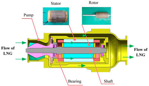
FIGURE 1. Submerged LNG pump with the cryogenic motor.
The cryogenic permanent magnet synchronous motor (CPMSM) is of high efficiency, high torque density, and large air gap, so it will gradually become the research and development trend of the cryogenic motor of LNG pump (Ai and Huang, 2015). The author of this study has conducted relevant research on CPMSM in the early stage (Guo et al., 2018a; Guo et al., 2018b). Since studies on the operational performance of cryogenic permanent magnet motor in the cryogenic environment (−161°C) have not been reported currently, based on the design of LNG pump cryogenic asynchronous motor (Miyagi et al., 2010; Pronto et al., 2011) and practical application experience, this study takes the 18.5 kW CPMSM prototype for submerged LNG pumps as the research object and carries out the simulation and experimental study on its efficiency, power factor, current, and torque under variable power. The research results will provide an important theoretical basis for the design, analysis, and operation control of the submerged LNG pump CPMSMs.
The rest of the article is organized as follows: Section 2 describes the design method of CPMSMs that is different from the conventional PM motors. The magnetic field distribution, electromotive force, voltage, and current of the proposed motor are simulated and analyzed in Section 3. The accuracy of the simulation model is verified by the prototype experiments in Section 4. The main operational characteristics of the motor are discussed in Section 5 based on the simulation and test results, and conclusions are drawn in Section 6.
According to the type spectrum of TC34 soaking centrifugal pump in Nikkiso Clean Energy and Industrial Gases Group (www.cryopump.com), the power range of induction motor with a speed of 0–7,200 rpm at 380 V voltage level is 12.6–27.1 kW. Referring to the product planning of similar cryogenic pumps manufactured by Dalian Deep Blue Pump Industry Co., Ltd., this study selects the motor with a power level of 18.5 kW and a maximum speed of 6,000 rpm as the research object. To meet the actual needs of users, an 18.5 kW CPMSM for a submerged LNG pump has been developed, and the specific parameters required are shown in Table 1.
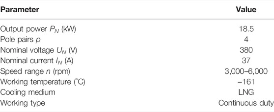
TABLE 1. 18.5 kW CPMSM prototype parameters.
The motor uses a built-in magnetic circuit structure. To increase the torque density and reduce the ends of the windings, V-shaped magnetic poles are adopted to place more permanent magnets. To reduce the rotational inertia and sufficiently cool, the rotor core is provided with axially symmetrical axial through holes in the circumferential direction.
Due to the decrease of the stator winding resistance and the increase of permanent magnet (PM) remanence in a cryogenic environment, the conventional design method is not suitable for the proposed CPMSM. A cryogenic temperature (CT) design method is used to develop the CPMSM in this study, which suggests such a redesign idea based on an original conventional design: reduce the stator slot area by a certain ratio, which is the same as that of the conductor resistance decrease; also reduce the PM volume by a certain ratio, which is inversely proportional to that of the remanence increase. As shown in Figure 2, the slot area and PM volume to be redesigned by the CT method can be given by
where, R, Rr,CON, and Rcry,CT, respectively, denote the conductor resistance, the equivalent resistance at room temperature by conventional design, and the equivalent resistance at cryogenic temperature by CT design (Ω); L denotes the conductor length (mm); S, SCON, and SCT, respectively, denote the slot area, the slot area by conventional design, and the redesigned slot area by CT design (mm2); ρCucry and ρCur, respectively, denote the conductor resistivities at cryogenic temperature and the conductor resistivities at room temperature (Ω∙mm2/m); E0, E0r,CON, and E0cry,CT, respectively, denote the no-load back EMF, the no-load back EMF at room temperature by conventional design and the no-load back EMF at cryogenic temperature by CT design (V); V, VCON, and VCT respectively denote the PM volume, the PM volume by conventional design, and the PM volume by CT design (mm3); Br, Brr, and Brcry respectively denote the PM remanence, the PM remanence at room temperature, and the PM remanence at cryogenic temperature (T).
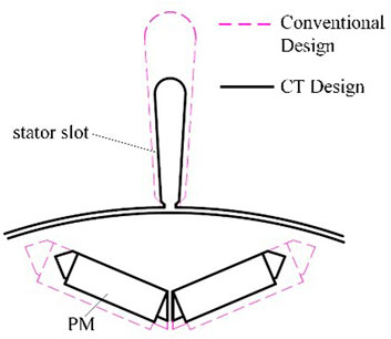
FIGURE 2. Change of the slot and PM dimensions redesigned by the CT method.
The total volume of the motor can also be reduced by decreasing the motor diameter according to the reduction ratio of slot area and PM dimensions, while maintaining the slot pitch, pole-pair, air-gap length, and core length, as shown in Figure 3. It can be seen that by using the CT method, the stator area can be reduced by nearly 1/3, and correspondingly the conductive material (copper) can be reduced by nearly 1/3; the rotor slot area can be reduced by 1/4, and correspondingly the permanent magnet area can also be reduced by nearly 1/4. However, the magnetic conductivity of silicon steel decreases at low temperatures. In order to keep the magnetic density unchanged, the reduction of stator and rotor area will be reduced. The outer diameter of the motor is reduced from 245 to 210 mm, which is nearly 1/5. According to the stator outer diameter standard, the motor size is reduced by a standard base center height.
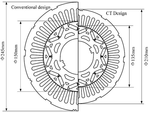
FIGURE 3. Design of the cryogenic PMSM by the CT method compared with the conventional design.
CPMSM in stable operation has the same loss as the motor at normal temperature, the electrical resistivity is 1/8 of that at room temperature, but the friction loss of the rotor and liquid nitrogen shall be considered, as shown in Figure 4.
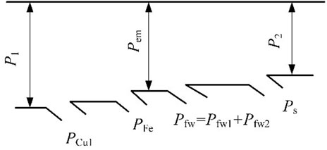
FIGURE 4. Power procedure of the CPMSM.
Stator copper loss PCu1 can be calculated according to the following formula:
Stator core loss can be analyzed according to the Bertotti iron loss calculation model (Miyagi et al., 2010), and the formula is shown as follows:
where Bm is the flux density magnitude, f is the alternate frequency, ke is the loss coefficient of turbine, kh is the magnetic hysteresis loss, and kc is the additional loss.
According to Dlugiewicz et al. (2012), the magnetic conductivity of silicon steel sheets is slightly improved at low temperature −196°C, but it is not different from that at normal temperature. However, the increase in iron loss at low temperatures is obvious when the flux density is saturated. Therefore, it is more appropriate to value the magnetic load of the motor at normal temperature in order not to increase the iron loss of the motor when designing the cryogenic motor.
The output shaft power P2 of the motor can be obtained after deducting the mechanical loss pfw and stray loss ps from the electromagnetic power Pem
where the mechanical loss pfw includes the bearing friction loss pfw1 and the friction loss pfw2 of rotor and liquid.
The bearing friction loss pfw1 of the motor at normal temperature is approximately equal to that of the motor at low temperature, and the friction loss pfw2 is several times that of the air at a normal temperature according to the density-dynamic viscosity ratio in the physical properties of liquid nitrogen shown in Table 1, so the friction loss pfw of rotor and liquid cannot be neglected, and the calculation formula is as follows:
where ρ is the liquid density; Lef is the core length of the motor [m]; ω is the rotation speed of the motor; Di2 is the rotor’s outer diameter; Cf is the friction coefficient, which is related to the flow pattern and physical properties of the fluid in the air gap of the motor.
The stray loss ps shall be calculated according to IEC 60034-2-1 (Spc, 2012), the stray loss at different loads shall be calculated according to that at rated load and the formula is shown as follows:
where IN is the rated current of the motor and PsN is the stray loss when the motor outputs the rated power.
The calculated mechanical loss pfw and miscellaneous ps shall be substituted into Eq. 5, the output power P2 of the motor can be obtained, and the operating efficiency of the prototype can be calculated according to the input power P1.
On the one hand, the motor shall be installed in the pump for the load test, so it is unable to directly measure the torque, speed, and other key parameters of the cryogenic motor; on the other hand, to ensure test safety, the motor shall be tested in liquid nitrogen (the temperature is −196°C under the pump pressure), the measured performance of the cryogenic motor has some differences from the actual operation in LNG (−161°C). Therefore, a more accurate simulation model of CPMSM is particularly important.
The CPMSM is modeled in ANSYS software, as shown in Figure 5, based on the design mentioned earlier.
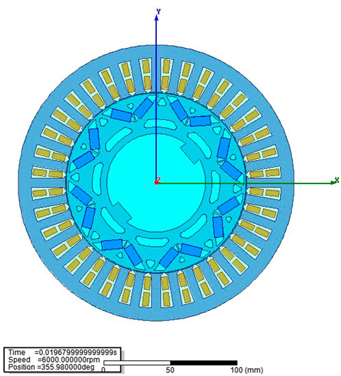
FIGURE 5. Sectional view of the model of the CPMSM prototype.
In view of the particularity of the application environment of the cryogenic motor, the distribution of the magnetic density and the friction coefficient of the rotor surface are very different from those of the common motor. In the simulation settings, the mesh generation is two times thinner than the ordinary generation to accurately analyze the magnetic density distribution of each surface, and the rotor friction coefficient is more than three times that of the conventional motor. The simulation time is set to 1 min to verify the stability and consistency of the output parameters.
Since the electrical resistivity ρCu of the conductive material decreases, the residual magnetism Br of the permanent magnet increases, and the magnetic conductivity changes little at the cryogenic state, it is necessary to correct the equivalent circuit parameters according to the changes in ρCu and Br parameters with the temperature when analyzing the cryogenic motor. It is also required to calculate the friction loss of the rotor due to liquid nitrogen (−196°C) accurately, and calculate the corresponding equivalent circuit parameters under −196°C liquid nitrogen, according to the parameters of the developed prototype, as shown in Table 2.

TABLE 2. Simulation parameters of the prototype in liquid nitrogen (−196°C) and LNG (−161°C).
No-load and load finite element simulations have been carried out, respectively, according to the aforementioned method. Figure 6 shows the magnetic flux density distribution of the motor, and the stator yoke and the tooth magnetic flux density are below 1.5 T under no-load conditions. The effective value of air-gap flux density is about 0.5 T as can be calculated according to Figure 6C.
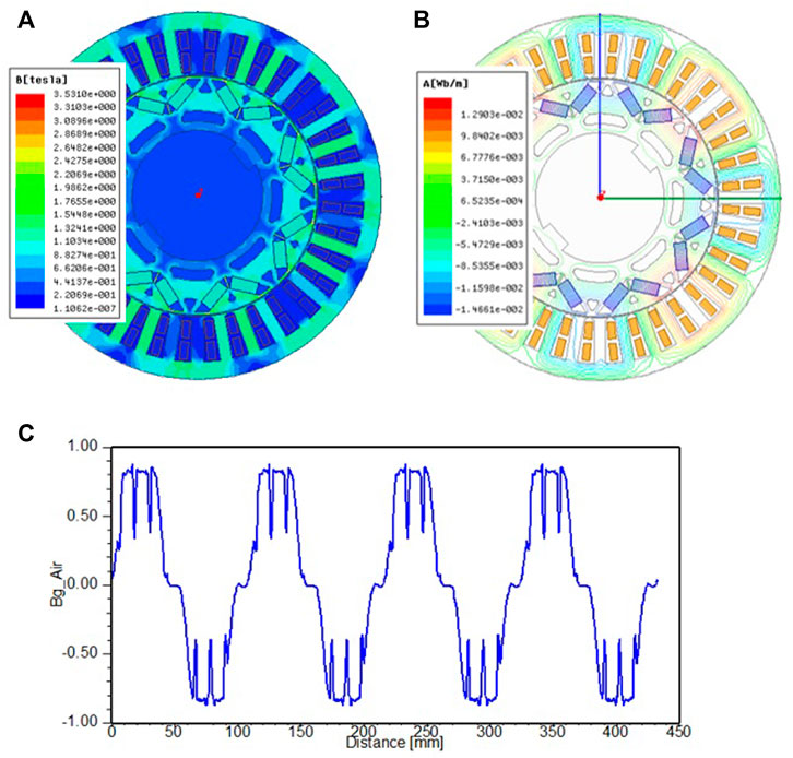
FIGURE 6. Magnetic flux density distribution of the motor: (A) cloud chart of the motor tooth and yoke magnetic flux density; (B) chart of the magnetic flux line; (C) waveform of the air-gap flux density.
According to the simulation results shown in Figure 6, the stator and rotor magnetic density and air gap waveforms of the CPMSM are similar to those of the motor at room temperature under the condition of reducing the slot area and permanent magnet volume. There is no over saturation of magnetic density and distortion of magnetic field lines and air gap waveforms, which verifies the correctness of Formulas 1, 2.
The no-load back EMF waveform of the motor is shown in Figure 7, and it can be known that the effective value of back EMF of line is 370 V from analysis after Fourier decomposition.
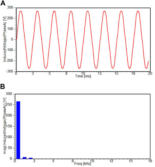
FIGURE 7. Back electromotive force (EMF) of phase at no-load in the liquid nitrogen (−196°C): (A) no-load back EMF waveform; (B) Fourier decomposition of back EMF shown in (A).
For safety reasons, the actual test will be carried out in a liquid nitrogen environment. Therefore, the parameters of conductive materials and permanent magnets used in the simulation are set according to the physical characteristics of the liquid nitrogen environment. The friction coefficient of the rotor surface in liquid nitrogen is completely different from that in air, so it should be set according to Formula 6 during simulation.
For load simulation, it is usually set with reference to the actual experimental conditions. Figure 8 shows the simulation waveforms of voltage and current in the liquid nitrogen (−196°C). From the simulation waveform and value of the load current and voltage of the CPMSM, it is within the range of design requirements. The waveform is smooth, and there is no distortion or three-phase current asymmetry. Due to the influence of spatial harmonics, the test waveform has a certain distortion, and the waveform obtained by simulation is relatively ideal, which often leads to some differences between the measured and the simulation results. The specific analysis and comparison will be explained in the experimental part of Section 4.
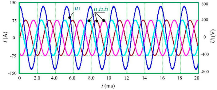
FIGURE 8. Simulation waveforms of voltage and current in liquid nitrogen (−196°C).
As the test standards on the CPMSM are not seen yet in the documents, the study by Boglietti et al. (2000) and China’s three-phase permanent magnet synchronous motor test standard (Iec, 2014) are referenced. The load characteristics and the torque characteristics of the CPMSM prototype were tested, respectively.
As natural gas is flammable, the liquid nitrogen (−196°C) instead of LNG (−161°C) for the overall test of the pump is selected for safety reasons. The fluid properties of liquid nitrogen and LNG are shown in Table 3.
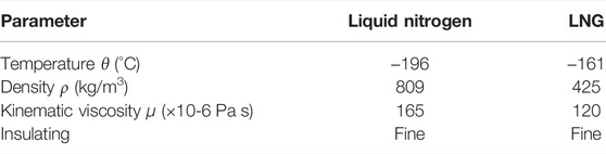
TABLE 3. Characteristics of liquid nitrogen and LNG.
Due to the limitation to the operating environment, the power cannot be obtained by directly measuring the speed and torque of the cryogenic motor. Instead, the density and flow rate of liquid nitrogen will be determined by measuring the pressure and temperature of the inlet and outlet of the pump, and then we can find out the corresponding head and shaft power through characteristics of the curve of the pump impeller. At the same time, the motor input voltage, current, and other parameters can be measured with the oscilloscope’s voltage, and current probe.
The test device is shown in Figure 9. The special controller for the permanent magnet motor GTAKE GK800 is used to drive the prototype. Since the test system is closed and self-circulating in the whole pipeline, it is necessary to add a bypass pipeline when testing the motor. After the motor is started, the valve is used to gradually switch to the liquid nitrogen pipeline, and then the self-circulating test is realized.
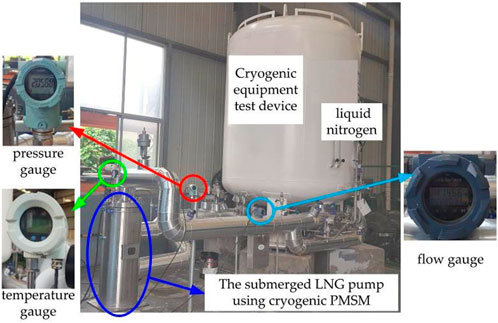
FIGURE 9. Liquid nitrogen (−196°C) test device.
When there is no load, the liquid nitrogen valve is turned off, the pump bypass channel is opened, and at this time, the readings of the export pressure gauge and flow meter are zero.
When there is load, the liquid nitrogen valve is opened and the output frequency of the controller is adjusted to improve speed. When the reading of the outlet pressure gauge reaches 2 MPa, readings of the flow meter greater than 20 m3/h (head 200 m), and the output power of the pump permanent magnet motor rated, the Tektronix MDO3014 oscilloscope is used to measure the waveform of the input line voltage U1 and the input line currents i1, i2 when the motor is rated, as shown in Figure 10.
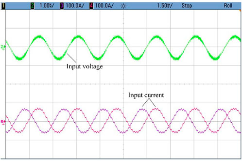
FIGURE 10. Measured waveforms of voltage and currents in liquid nitrogen (−196°C).
Compared with the simulation waveform shown in Figure 8, the experimental results are basically consistent with that of the simulation. The corresponding simulation and test data are shown in Table 4. Compared with simulation and test waveforms, the current waveform recorded by the test is distorted to some extent due to the space harmonics, resulting in certain differences between the measured power factor and the simulation result. Overall, the simulation result shows high consistency with the test waveform, indicating that the established model of CPMSM can calculate the operating parameters of the motor accurately.
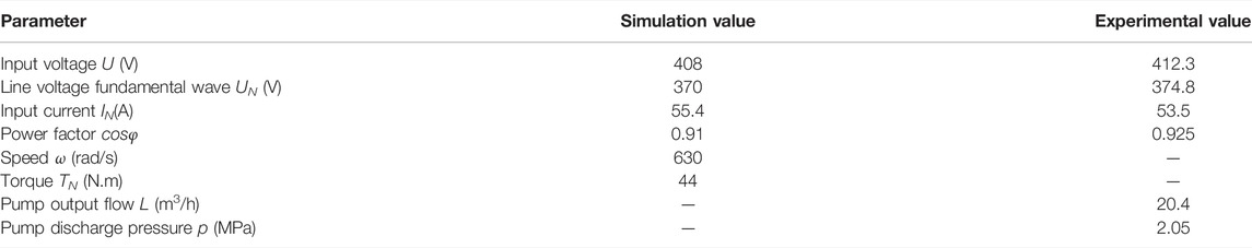
TABLE 4. Simulation and experiment results of the prototype in liquid nitrogen (−196°C).
It can be seen from Table 4 that the effective value of input voltage is 374.8 V at rated load and the effective value of the current is 53.5 A, which are measured when the pressure and flow in the pump are stable according to the readings of the pressure gauge and flow gauge. The test results show that the prototype can run well in liquid nitrogen, and the torque reaches the requirements of a submerged LNG pump, which proves the rationality of the design. However, it shall be noted that the tested current of the prototype (including the corresponding simulation results) is about 1.6 times the rated current of 37 A at the rated speed, as shown in the table. The reason is the density and viscosity of liquid nitrogen used in the experiment and simulation are both greater than those of LNG, so the output torque of the prototype in liquid nitrogen is higher, making the current larger.
It should be noted that the density of liquid nitrogen is 1.9 times that of LNG, and the kinetic viscosity is 1.35 times of LNG, that will result in greater output torque in the liquid nitrogen load operation at the same speed. Therefore, there must be some differences between the test results and the actual operating results in LNG. Figure 11 shows the power curve obtained when operating in these two media. At the same time, it is easy to conclude that if the prototype can run in liquid nitrogen for a long time, then it will reach the operating requirements of LNG.
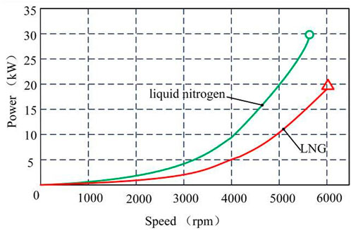
FIGURE 11. Power curves of the CPMSM when operating in liquid nitrogen and LNG.
Based on the aforementioned simulation and test data, the operational performance of the prototype can be further analyzed.
According to the model and calculation program of the CPMSM established previously, the operating characteristics of the prototype under −196°C liquid nitrogen environment can be calculated, as shown in Figure 12. In the figure, the x-coordinate P2/PN is the ratio of output power P2 and rated power PN, and the y-coordinate is normalized, including the power factor cosφ, efficiency η, and the per-unit value of stator input line current I1*.
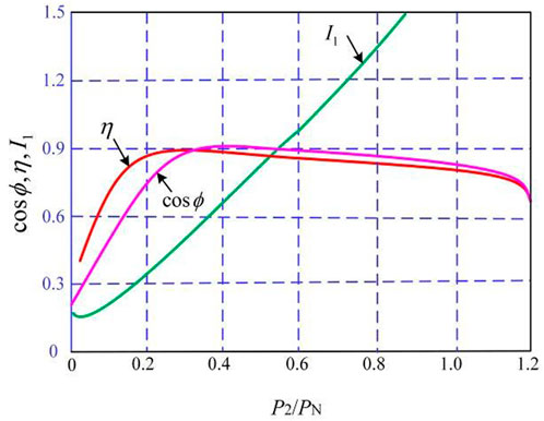
FIGURE 12. Prototype-operating characteristics in liquid nitrogen (−196°C).
The operating efficiency and power factor of the prototype are very high within the output power range of 0.2PN∼1.2PN. The reason why the CPMSM has such excellent drive characteristics is that the fixed resistance of the motor at low temperature is small, the rotor has no loss, and the no-load of the motor is very small, so the efficiency curve increases rapidly with the increase in the load. When the variable loss is equal to the constant loss (PCu1+ ps = PFe + pfw), the efficiency η reaches the maximum. As the output power P2 continues to increase, the variable copper loss (PCu1 = mI2R1) of the CPMSM increases slowly and its efficiency slows down. Therefore, the CPMSM can maintain high efficiency and high power factor operation within a wide range of output power.
The mechanical characteristics Te-I of liquid nitrogen (−196°C) of the prototype can also be calculated, and the maximum electromagnetic torque Temax can be obtained under different I-amplitude conditions. The curve is shown in Figure 13, indicating the variation of the maximum electromagnetic torque of the same current output and the maximum torque value Kt (Kt = Temax/I) of the corresponding unit current with the current space vector amplitude I.
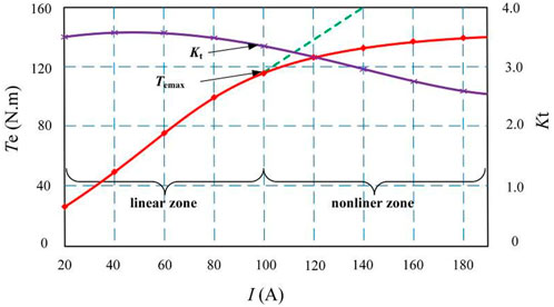
FIGURE 13. Changing curve of Tmax and Kt with current.
Through the analysis of Te−I curve of the prototype, it can be found that the overall trend is basically the same as that of the motor at normal temperature, but there is also a certain difference. Owing to the increase in the residual magnetism Br of the permanent magnet at low temperature, the maximum torque is slightly greater than that of the motor at a normal temperature at the torque coefficient Kt in the linear region (the magnetic circuit is not saturated). However, the reluctance torque is rapidly decreased by the saturation of the magnetic circuit at low temperature in the linear region (the magnetic circuit is saturated), resulting in a decrease in the output torque of the prototype per unit, that is, Kt is smaller than that of the motor at normal temperature. Therefore, it is not recommended to increase the magnetic load of the cryogenic motor, which can be taken according to the normal temperature, that is, the flux density of each part of the motor rotor and stator does not exceed 1.5T (Miyamoto et al., 2011; Bernard et al., 2016; Lv et al., 2019), and the gap flux density Bg is about 0.5T.
As mentioned earlier, considering the safety of the test, the prototype is tested in liquid nitrogen, and it actually runs in LNG. Because the temperature and physical properties of liquid nitrogen and LNG are different, the parameters and rotor friction loss of the prototype in the two liquids are also different (Ai et al., 2015). Using the aforementioned simulation model and the prototype parameters shown in Table 2, the operating performance of the prototype in LNG (−161°C) is analyzed, and the relevant curves are shown in Figure 14.
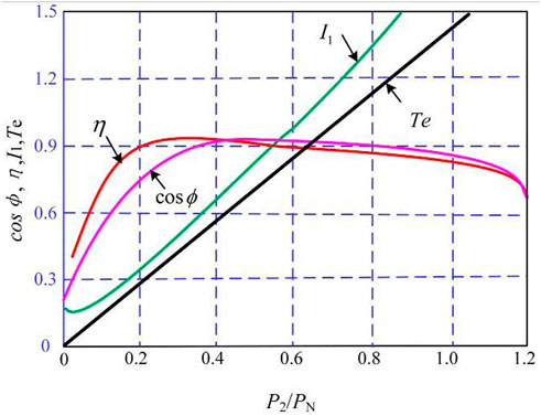
FIGURE 14. Prototype operating characteristics in the LNG (−161°C).
Compared with the calculation results of that running in LNG and liquid nitrogen, the operating characteristics of the prototype change little. In addition, its operating efficiency in LNG is slightly higher than that in liquid nitrogen.
An 18.5 kW CPMSM for a submerged LNG pump is studied. A CT design method is used to develop the CPMSM, the simulation modeling and analysis are carried out, and the liquid nitrogen test platform is built. The test results are very close to the simulation results.
Based on the theory of electric machinery and using the simulation and experimental data, this study also makes further analysis and research on the operational performance of the CPMSM and draws the following conclusion:
(1) The CPMSM can maintain high efficiency and high power factor operation within a wide range of output power.
(2) The torque coefficient Kt of the CPMSM is slightly higher than that at normal temperature when the magnetic circuit is not included.
(3) Although the current tested in liquid nitrogen is about 1.6 times that in LNG due to the physical difference between the two liquids, there is little difference in the operating characteristics of the CPMSM in liquid nitrogen and LNG. Therefore, it is reasonable to use liquid nitrogen for testing the CPMSM.
With the continuous development and improvement of the magnetic material, design, and control technology of CPMSM, it will be better applied in the submerged LNG pumps.
The raw data supporting the conclusion of this article will be made available by the authors, without undue reservation.
Conceptualization, CG and YF; methodology, SH; software, CG; validation, JW and YF; formal analysis, JW; investigation, CG; resources, JW; data curation, CG; writing—original draft preparation, CG; writing—review and editing, YF; visualization, JW and YF; supervision, SH; project administration, SH; funding acquisition, YF. All authors have read and agreed to the published version of the manuscript.
This research was funded by the Natural Science Foundation of Hunan Province (2019JJ70063, 2021JJ30107, and 2022JJ30195) and the Outstanding Youth Project of the Department of Education of Hunan Province (20B132, 21B0875).
The authors declare that the research was conducted in the absence of any commercial or financial relationships that could be construed as a potential conflict of interest.
All claims expressed in this article are solely those of the authors and do not necessarily represent those of their affiliated organizations, or those of the publisher, the editors, and the reviewers. Any product that may be evaluated in this article, or claim that may be made by its manufacturer, is not guaranteed or endorsed by the publisher.
Ai, Chengliu, and Huang, Yuanfeng (2015). Important Parameters Design of Inverter-Driven Cryogenic Induction Motor for Submerged Liquid Natural Gas Pump. Proc. CSEE 35 (20), 5317–5326.doi:10.13334/j.0258-8013.pcsee.2015.20.025
Ai, Chengliu, Huang, Yuanfeng, Wang, Haifeng, and Gu, Guobiao (2015). Research on the Operating Performance of an Inverter-Driven Cryogenic Induction Motor for a Submerged LNG Pump. Trans. China Electrotech. Soc. 30 (14), 138–145.
Baranski, M., and Szelag, W. (2012). Finite-element Analysis of Transient Electromagnetic-Thermal Phenomena in a Squirrel-Cage Motor Working at Cryogenic Temperature. IET Sci. Meas. Technol. 6 (5), 357–363.
Bernard, N., Missoum, R., Dang, L., Bekka, N., Ben Ahmed, H., and Zaim, M. E.-H. (2016). Design Methodology for High-Speed Permanent Magnet Synchronous Machines. IEEE Trans. Energy Convers. 31 (2), 477–485. doi:10.1109/tec.2015.2513669
Boglietti, A., Lazzari, M., and Pastorelli, M. (2000). A Simplified Method for the Iron Losses Prediction in Soft Magnetic Materials with Arbitrary Voltage Supply. IEEE-IAS Annu. Meet. 1, 269–276. doi:10.1109/IAS.2000.881117
Dlugiewicz, L., Kolowrotkiewicz, J., and Szelag, W. (2006). Electrical Motor for Liquid Gas Pump. International Symposium on Power Electronics. Sicily, Italy. 23-26 May. Nagasaki University, University of Napoli, University of Cassino and University of Catania, 28–33.
Dlugiewicz, L., Kolowrotkiewicz, J., and Szelag, W. (2012). Permanent Magnet Synchronous Motor to Drive Propellant Pump. International Symposium on Power Electronics, Electrical Drives, Automation and Motion. Sorrento, Italy. 20-22 June. IEEE, 822–826.
Guo, C., Huang, S. D., Wang, J. B., and Feng, Y. J. (2018). Design of Cryogenic Permanent Magnet Synchronous Motor for Submerged Liquefied Natural Gas Pump. IEEE Trans. Mag. 54 (11), 8207405. doi:10.1109/tmag.2018.2832005
Guo, C., Huang, S., Wang, J., and Feng, Y. (2018). Research of Cryogenic Permanent Magnet Synchronous Motor for Submerged Liquefied Natural Gas Pump. IEEE Trans. Energy Convers. 33 (4), 2030–2039. doi:10.1109/tec.2018.2868954
Hui, M. K., Lee, K. W., Kim, D. G., Park, J. H., and Park, G. S. (2018). Design of Cryogenic Induction Motor Submerged in Liquefied Natural Gas. IEEE Trans. Magn. 54 (3), 8201204. doi:10.1109/TMAG.2017.2751099
Iec 2014 “Standard Methods for Determining Losses and Efficiency from Tests (Excluding Machines for Traction Vehicles),” in IEC 60034-2-1 Rotating Electrical Machines (Switzerland: IEC).
Kolowrotkiewicz, J., Baranski, M., Szeleg, W., and Dlugeiwicz, L. (2007). FE Analysis of Induction Motor Working in Cryogenic Temperature. COMPEL Int. J. Comput. Math. Electr. Electron. Eng. 26 (4), 952–964. doi:10.1108/03321640710756294
Liping Zheng, Liping, Wu, T. X., Acharya, D., Sundaram, K. B., Vaidya, J., Limei Zhao, fnm, et al. (2005). Design of a Superhigh-Speed Cryogenic Permanent Magnet Synchronous Motor. IEEE Trans. Magn. 41 (10), 3823–3825. doi:10.1109/tmag.2005.854983
Miyagi, D., Otome, D., Nakano, M., and Takahashi, N. (2010). Measurement of Magnetic Properties of Nonoriented Electrical Steel Sheet at Liquid Nitrogen Temperature Using Single Sheet Tester. IEEE Trans. Magn. 46 (2), 314–317. doi:10.1109/tmag.2009.2033551
Miyamoto, Masaki, Matsuo, Tetsuji, and Nakamura, Taketsune (2011). Measurement of Vector Hysteretic Property of Silicon Steel Sheets at Liquid Nitrogen Temperature. Przeglad Elektrotechniczny Electr. Rev. 87 (9B), 111–114.
Pronto, A. G., Neves, M. V., and Rodrigues, A. L. (2011). Measurement and Separation of Magnetic Losses at Room and Cryogenic Temperature for Three Types of Steels Used in HTS Transformers. J. Supercond. Nov. Magnetism 24(1), 981–985. doi:10.1007/s10948-010-0867-9
Rush, S., and Hall, L. (2001). Tutorial on Cryogenic Submerged Electric Motor Pumps, Proceedings of the International Pump Users Symposium. Houston, USA. 5-8 March. 101–107. The Turbomachinery Laboratory at Texas A&M University.
Shively, R. (2003). Submerged Cryogenic Motor Materials Development. IEEE Electr. Insul. Mag. 19 (3), 7–11. doi:10.1109/mei.2003.1203016
Spc 2012. GB/T 1032—2012 Three-phase Asynchronous Motor Test Method. General Administration of Quality Supervision, Inspection and Quarantine of the People's Republic of China, Standardization Administration of the People's Republic of China. Beijing, China: Standard Press of China.
Tessarolo, A., Zocco, G., and Tonello, C. (2011). Design and Testing of a 45-MW 100-Hz Quadruple-Star Synchronous Motor for a Liquefied Natural Gas Turbo-Compressor Drive. IEEE Trans. Ind. Appl. 47 (3), 1210–1219. doi:10.1109/tia.2011.2126036
Lv, X. Y., Sun, D. Y., and Sun, L. Z. Determination of Iron Loss Coefficients of Ferromagnetic Materials Used in Cryogenic Motors. 22th International Conference on Electrical Machines and Systems (ICEMS), Harbin, China. 11-14 Aug. 2019.
Keywords: LNG pumps, cryogenic motor, finite element simulation, liquid nitrogen test, operational performance
Citation: Guo C, Feng Y, Huang S and Wang J (2022) Operational Performance Analysis of the Cryogenic Electrical Machine for Submerged Liquefied Natural Gas Pumps. Front. Energy Res. 10:922888. doi: 10.3389/fenrg.2022.922888
Received: 18 April 2022; Accepted: 16 June 2022;
Published: 22 July 2022.
Edited by:
Angelo Maiorino, University of Salerno, ItalyReviewed by:
Fubin Yang, Beijing University of Technology, ChinaCopyright © 2022 Guo, Feng, Huang and Wang. This is an open-access article distributed under the terms of the Creative Commons Attribution License (CC BY). The use, distribution or reproduction in other forums is permitted, provided the original author(s) and the copyright owner(s) are credited and that the original publication in this journal is cited, in accordance with accepted academic practice. No use, distribution or reproduction is permitted which does not comply with these terms.
*Correspondence: Jiabao Wang, d2piMDEyMEAxNjMuY29t
†These authors have contributed equally to this work
Disclaimer: All claims expressed in this article are solely those of the authors and do not necessarily represent those of their affiliated organizations, or those of the publisher, the editors and the reviewers. Any product that may be evaluated in this article or claim that may be made by its manufacturer is not guaranteed or endorsed by the publisher.
Research integrity at Frontiers
Learn more about the work of our research integrity team to safeguard the quality of each article we publish.