
94% of researchers rate our articles as excellent or good
Learn more about the work of our research integrity team to safeguard the quality of each article we publish.
Find out more
ORIGINAL RESEARCH article
Front. Energy Res., 13 June 2022
Sec. Nuclear Energy
Volume 10 - 2022 | https://doi.org/10.3389/fenrg.2022.915450
This article is part of the Research TopicExperimental and Analytical Investigations on Nuclear Reactor Safety, Severe Accident Phenomena and Severe Accident Mitigation of Nuclear Power PlantsView all 20 articles
 Jian DengDahuan Zhu
 Yuejian Luo*Hongping SunMing ZhangLili LiuQingan XiangXiaoli WuYouyou XuQingwen Xiong
Understanding a reliable description of the heat transfer in the molten pool with three-layer configuration is inevitable for the design of severe accident mitigation measures in research reactors, such as IVR-ERVC. However, investigations on a thick lower metallic layer are scarce. Thus, further studies on heat transfer in a molten pool with a thick lower metallic layer are highly required, based on previous severe accident studies in light water reactors. This study conducts a numerical simulation of heat transfer in the molten pool with a thick lower metallic layer during a severe accident, combining model development, code verification, and code application. First, the MPCAP code has been developed, based on the coupled simulation of natural convection inside the molten pool, two-dimensional heat conduction in the RPV lower head, and convection outside the reactor vessel wall. Then, a verification case has been conducted using three-layer configuration in AP1000. The AP1000 verification case indicates that the MPCAP code predicts important parameters in the molten pool well.
At present, the proportion of nuclear energy is low. Nuclear energy, a clean energy with a large space for development, is an important component of sustainable energy structure. In the process of development of nuclear energy science, research reactors which are used for scientific research, operational training, and technological development play an important role in many fields, such as physics, chemistry, biology, medicine, and agriculture, . According to the latest statistics from the International Atomic Energy Agency (IAEA), there are 258 operational research reactors in 56 countries and territories worldwide (RRDB, 2020).
Nuclear safety has been the focus of public attention since the beginning of the development of nuclear energy, and safety analysis has always been the focus of nuclear energy scientific research. Since the Three Mile Island accident and the Chernobyl accident, the severe accident of nuclear reactor has received wide attention in the international community, and the IAEA has explicitly required that severe accident and their mitigation measures must be taken into account in the design of nuclear power plants (Gilbert, 1979). The National Nuclear Safety Administration of China issued the Regulations on the Design and Safety of Nuclear Power Plants (HAF102-2016) which also requires additional safety facilities for the design of nuclear power plants, the expansion of safety system capabilities, the prevention of severe accidents, and the mitigation of the consequences of a severe accident. The IAEA Research Reactor Safety also states that the potentially serious consequences of all foreseeable events must be taken into account in the design of the research reactor and that safety facilities can prevent severe accidents and mitigate the consequences of severe accidents (Safety of Research Reactors, 2016).
It is an important part of severe accident research to formulate measures to relieve severe accident mitigation and reduce the serious consequences of core melting. How to deal with core melting is a key point in the mitigation measures of a severe accident, and the significant mitigation measure adopted by advanced nuclear power plants includes in-vessel retention (IVR) and ex-vessel retention (EVR). In reactors with a semi-sphere shape pressure vessel, the external reactor vessel cooling (ERVC) is used to remove the decay heat from the lower head of the pressure vessel and maintains the integrity of the lower head. Some research reactors also have a semi-sphere shape pressure vessel, which is a foundation of IVR-ERVC implementation. On the basis of the application of IVR-ERVC for commercial light water reactors, the IVR-ERVC measure could be adopted in research reactors, which is conducive to the formulation of mitigation measures for a severe accident.
By research studies on pressure vessels with molten materials in the Three Miles Island nuclear accident, it is presented that the core molten materials will be relocated to the pressure vessel's lower plenum, and eventually form a molten pool. In spite of decay heat, the pressure vessel can still maintain integrity. On this basis, a retention strategy for molten material in the lower plenum is proposed for reactors with a semi-sphere shape lower head. At first, IVR-ERVC has been used in the VVER-440 unit in Loviisa nuclear power plant (Kymäläinen et al., 1997), and gradually adopted as a key technology for the retention strategy for molten materials in reactor lower plenum, such as AP1000, ACP1000, CPR1000, CAP1400, APR1400 (Rempe et al., 1997; Theofanous et al., 1997; Cummins et al., 2003; Esmaili And Khatib-Rahbar, 2004; Oh And Kim, 2005; Wang et al., 2010; Li et al., 2015).
In commercial light water reactors, a steady-state molten pool, which is considered to be formed under an enveloped condition, generally consists of two- and three layers, as shown in Figure 1. The two-layer molten pool includes a lower oxide layer and an upper metallic layer. The oxide layer with an internal heat source has uranium dioxide, zirconium dioxide, and other oxides, and the metallic layer has stainless steel, and zirconium alloy, generally believed to have no internal heat source. The three-layer molten pool includes a lower heavy metallic layer, intermediate oxide layer, and upper light metallic layer. The heavy metallic layer with an internal heat source has metal uranium, stainless steel, and zirconium alloy. The decay heat in the oxide layer heats the heavy metallic layer and the light metallic layer. The light metallic layer is similar to the two-layer molten pool. It is generally believed that the precipitation of heavy metal uranium is less, and the heavy metallic layer is thinner. In addition, the heat transfer performance of heavy metal uranium is well, the heat in the heavy metallic layer is only conducted through the inner wall of the pressure vessel. Because of the high melting point of oxide molten materials, there is a crust around the oxide molten pool, and the inner temperature of the crust is the melting point of oxide molten materials. The configuration of the molten pool is closely related to molten components, the core melting process, and especially the relocation of molten materials to the lower head.
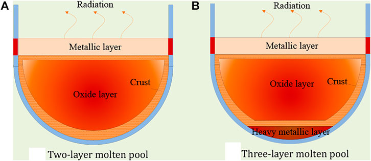
FIGURE 1. Schematic diagram of molten pool configuration. (A) Two-layer molten pool. (B) Three-layer molten pool.
Under the effect of the temperature difference and density difference, natural convection occurs inside a steady-state molten pool, and the heat transfer along the angle can be determined by empirical heat transfer correlations. On the one hand, the heat in a metallic layer is removed through upper radiation and conduction in the pressure vessel's inner wall surface. The thinner metallic layer leads to higher heat flux in the inner surface wall of the pressure vessel, which is easy to exceed the critical heat flux (CHF), resulting in the failure of the pressure vessel wall because of thermal load. This phenomenon is a focusing effect, which needs to be paid attention to. On the other hand, the power density of the heavy metallic layer is related to the quality of light metals such as dissolved zirconium alloy and stainless steel in heavy metal uranium. When the amount of desolvation is less, the heavy metallic layer is thinner and the power density is larger, which is easy to form a focusing effect in the lower heavy metallic layer. The focusing effect in the lower heavy mental layer is similar to that of the upper light metallic layer. Especially the CHF value decreases with angles, and thermal failure could occur near a heavy metallic layer located at the bottom of the pressure vessel.
In research reactors with U-Al alloy fuels, the molten materials include uranium dioxide, alumina, U-Al alloy, aluminum alloy. Oxide molten pool is mainly alumina-based, all obtained by high-temperature oxidation reaction. The molten metallic layer is mainly U-Al alloys, and less metallic aluminum alloys are extracted. The density of U-Al alloy is greater than alumina, forming a molten pool configuration with a lower thick metallic layer with U-Al alloy, a middle thinner oxide layer, and an upper thinner metallic layer. The internal heat source is concentrated in the lower molten pool and tends to conduct to the pressure vessel wall, which could make the middle oxide layer and upper metallic layer solidify, forming a three-layer molten pool configuration, as shown in Figure 2. Whether the oxide layer and metallic layer solidify is closely related to the heat source in the oxide layer and the upward heat transfer from the lower heavy metallic layer.
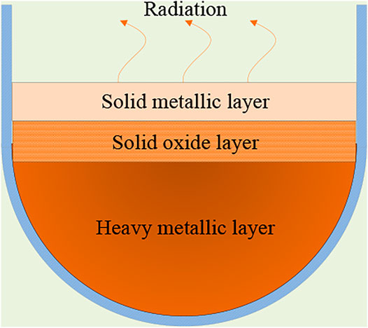
FIGURE 2. Schematic diagram of molten pool configuration with a lower heavy metallic layer.
At present, all heat transfer methods in the molten pool are focusing on the molten pool configuration of the light water reactor, and don’t apply to reactors with a thicker lower heavy metallic layer mentioned above. It needs to be studied based on the current heat transfer method in the molten pool. This method could include the determination of molten pool configuration, and heat transfer from the molten pool to the outer surface wall of the pressure vessel. Most heat transfer method in the molten pool is based on lumped parameter method, which has been studied by many researchers. Cao et al. have studied the two-dimensional conduction inside the lower headwall and heat convection outside the lower headwall (Cao et al., 2015). In addition, Liu et el. havefocused on the effects of heat transfer inside and outside molten pools by coupled analysis, which could decrease the focusing effects (Liu et al., 2018; Luo et al., 2018; Luo et al., 2019). These researches are important and significant for engineering assignment for large-scale nuclear power plants, especially decreasing the focusing effects, and also helpful in this study.
In this study, a new heat transfer method in the molten pool for a reactor with a thicker lower heavy metallic layer has been presented. Firstly, a molten pool configuration determination has been developed to solve whether a solidified middle oxide layer or upper metallic layer exists based on an improved lumped parameter method. Secondly, a comprehensive analysis has been adopted to solve the heat transfer in the molten pool based on previous coupled analysis, considering natural convection inside the molten pool, two-dimensional conduction inside the lower headwall, and convection outside the lower headwall. Then, an MPCAP (Molten Pool Coupled Analysis Program) code has been developed, and a verification calculation with AP1000 has been conducted.
This chapter develops a coupled analysis code MPCAP for heat transfer in the molten pool with a thick lower heavy metallic layer, on the basis of coupled analysis method using the improving lumped parameter method and detailed heat transfer from inside molten pool to the outside lower headwall.
In lumped parameter method, the molten pool is calculated as a whole using average parameter values, as shown in Figures 3–5.
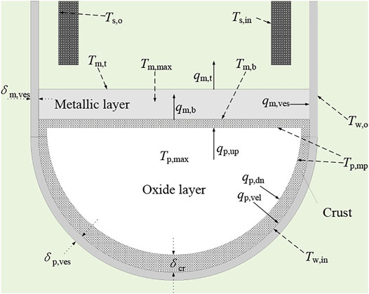
FIGURE 3. Schematic diagram of two-layer molten pool with parameters.

FIGURE 4. Schematic diagram of three-layer molten pool with parameters.
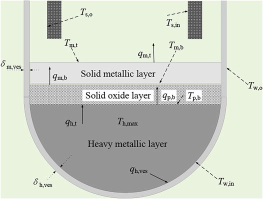
FIGURE 5. Schematic diagram of thick heavy metallic layers with parameters.
The traditional lumped parameter method indicates that the ratio of heat transfer up and down in the oxide layer is fixed and determined by the ratio of Nusselt number, which is obtained by the empirical correlation (Theofanous et al., 1997; Liu et al., 2018):
Using a heat balance relationship,
We get
Using the heat flux obtained by the abovementioned formulae, the total parameters in the oxide layer and metallic layer are calculated respectively, and the main parameters are obtained including the distribution of heat flux along the lower headwall, the thickness of crust, and the thickness of the lower headwall of the pressure vessel. In this calculation process, only one-dimensional conduction is considered, and the outer surface wall of the lower head is a fixed temperature or a fixed heat transfer coefficient.
This thickness of pressure vessel in commercial light water reactor is generally more than 15 cm, which is obvious two-dimensional conduction. Two-dimensional conduction can transmit heat from a higher temperature area axially to a lower temperature area, redistributing the temperature field inside the lower head, which has a protective effect on the focusing effect near the metallic layer. In the numerical simulation, the simple and conservative use of one-dimensional conduction will significantly overestimate the phenomenon of the focusing effect and cannot obtain accurate prediction results, making the evaluation results of IVR-ERVC conservative.
In the lower headwall of a pressure vessel, two-dimensional conduction and external convection had a significant impact on the heat transfer of the molten pool, and ultimately affect the heat flux distribution in the outer surface wall of the lower head. The traditional lumped parameter method above simply determines the up and down heat transfer by the ratio of Nusselt number, which is not consistent with the actual situation and couldn’t apply to molten pool configuration with a thicker lower heavy metallic layer. Later in this section, we will focus on the heat transfer in the molten pool based on the improved lumped parameter method and briefly introduce two-dimensional conduction and external vessel heat transfer.
This section is based on a three-layer molten pool configuration, including a lower heavy metallic layer, central oxide layer, and upper light metallic layer. When the power density of the heat source in the oxide layer is low, the heat in a heavy metallic layer may be transferred to the oxide layer, affecting the oxide layer and metallic layer. This section first discusses the configuration of the molten pool on the basis of heat transfer in the heavy metallic layer and determines the formation of the oxide layer and metallic layer in the molten pool. On the basis of judging the configuration of the molten pool, the heat transfer in the oxide layer and metallic layer are discussed. The main parameters are shown in Figure 4, at which the temperature of the oxide layer is highest and the heat is transferred from the oxide layer to the metallic layer and heavy metallic layer, respectively.
Different internal heat sources and heat transfer capability may cause different molten pool configurations. In the actual reactor molten pool, the decay power density in the heavy metallic layer is high, where the capacity of heat transfer is strong. In addition, the melting point of the lower heavy metallic layer is smaller, indicating that there is a molten state. The lower heavy metallic layer is cooled through the pressure vessel wall. Since the lower heavy metallic layer is thin, convection is not obvious, and conduction prevails. We can simply get heat flux to form a heavy metallic layer on the inner wall surface of the pressure vessel:
When the lower heavy metallic layer is thick, the natural convection is similar to the oxide layer, and the distribution of heat flux on the side of the lower heavy metallic layer can be obtained by using the Nusselt number distributed along angle:
The state of the oxide layer is related to the internal heat source of the oxide layer and the heat transfer between the heavy metallic layer and the oxide layer. When there is a sufficient internal heat source in the oxide layer, the heat is transmitted from the oxide layer to the metallic layer and heavy metallic layer, and the maximum temperature of the oxide layer is inside the oxide layer. When the maximum temperature is higher than the melting point of the oxide layer, a molten oxide layer is formed with crust. When there is an insufficient heat source in the oxide layer, the heat in the heavy metallic layer is transmitted to the oxide layer, and the maximum temperature of the oxide layer is at the bottom of the oxide layer. The solidification of the metallic layer is related to the internal heat source and upward heat transfer from the oxide layer to the metallic layer, and it is generally believed that the internal heat source in the metallic layer is low, and the solidification of the metallic layer is mainly related to the upward heat transfer from oxide layer.
For the molten pool with a thicker heavy metallic layer, there is an obvious internal heat source in the lower heavy metallic layer. The solidification of the oxide layer is the key to molten pool configuration. For a thinner solidified oxide layer and metallic layer, it is considered that there is only conduction like an infinite plate. The temperature distribution in the oxide layer and metallic layer is shown in Figure 6. The oxide layer is parabolic and the metallic layer is linear based on whether there is an internal heat source. When heat is transferred from a heavy metallic layer to an oxide layer, the maximum temperature of the oxide layer is in contact with the oxide layer, but it is not the vertex of the parabola. When heat is transferred from the oxide layer to the heavy metallic layer, the maximum temperature of the oxide layer is inside the oxide layer, which is the vertex of the parabola.
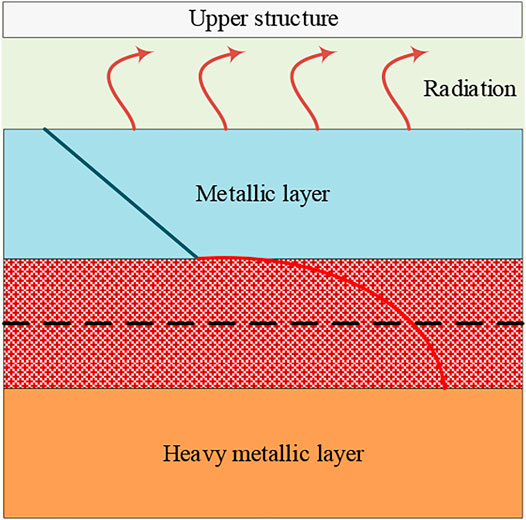
FIGURE 6. Schematic diagram of temperature gradient in the solid oxide layer.
To judge the heat transfer between the heavy metallic layer and oxide layer, it can be assumed that there is no heat transfer between those two layers, and then the temperature between the heavy metallic layer and oxide layer is distributed as a parabola type. In this situation, the maximum temperature of the heavy metallic layer is equal to the temperature at the top of the heavy metallic layer, and the temperature of the top of the oxide layer is equal to the temperature of the bottom of the metallic layer:
At the same time, the temperature at the bottom of the metallic layer:
Also,
The heat is radiated from the metallic layer to the upper space of the reactor core, mainly consisting of two parts: one is between the top surface of the metallic layer and the inner surface of the inner component of the pressure vessel reactor, and another is between the outer surface of the component of pressure vessel reactor and the upper inner surface of the pressure vessel. The inner component of the pressure vessel reactor includes upper structures, which don’t relocate to the lower head during severe accidents. Ignoring radiation between the top surface of the metallic layer and the pressure vessel, and simplifying the geometry of components inside the core as a flat rectangular, we can calculate the heat transfer in the upper space of the metallic layer. Radiation from the top surface of the metallic layer:
The internal conduction of components inside the core is approximated as one-dimensional conduction:
The outer surface of the reactor component is approximately equal to the upper inner surface area of the pressure vessel, and if the emission rate is the same, then the radiation is
Approximately, one-dimensional conduction in the upper-pressure vessel wall is
Obviously, in the abovementioned several heat transfer processes, the quantity of heat transfer is equal; then,
The bottom temperature of the metallic layer could be obtained above Eqs 10–16 or Eqs 7–9, which could be compared. If the former value is larger, then the heat is transferred from the oxide layer to the heavy metallic layer. On the contrary, the heat is transferred from the heavy metallic layer to the oxide layer. It is discussed, respectively, in the following part.
When heat is transferred from the oxide layer to the heavy metallic layer, at first, we assume that there is a parameter indicating the ratio of heat transfer from the oxide layer to the heavy metallic layer, and we set it as fph, equaling 0∼1. Then, Eq. 8 is written as
Also, Eq. 11 is written as
The temperature at the bottom of the oxide layer is equal to the temperature at the top of the heavy metallic layer:
By Eqs 7, 17–19, the temperature at the bottom of the oxide layer is obtained.
There is a symmetrical point in the temperature distribution of the oxide layer, as shown in Figure 7. When the maximum temperature is on the right, the symmetry temperature Tsym is equal to the temperature at the bottom of the oxide layer, which is Tp,b. When the maximum temperature is on the left, the symmetry temperature Tsym is equal to the temperature at the top of the oxide layer, which is Tp,t.
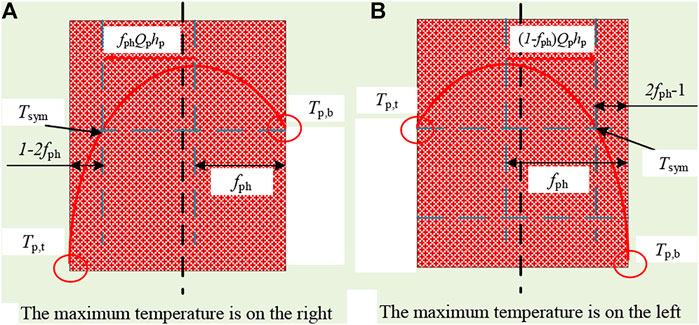
FIGURE 7. Schematic diagram of temperature symmetry in the solid oxide layer. (A) The maximum temperature is on the right. (B) The maximum temperature is on the left.
When the maximum temperature is on the right, meaning that fph < 0.5, and the temperature at the bottom of the metallic layer is
When the maximum temperature is on the left, meaning that fph > 0.5, the temperature at the bottom of the metallic layer is
The temperature at the bottom of the metallic layer obtained above is Tm,b, and also the temperature at the bottom of the metallic layer could be obtained by Eqs 10, 12–16, 18. For comparison, we adjust fph and repeat the above steps until the convergence limit is reached, and finally determine the ratio of heat transfer from the oxide layer to the heavy metallic layer.
When heat is transferred from the heavy metallic layer to the oxide layer, at first we assume that there is a parameter indicating the ratio of heat transfer from heavy metallic layer to the oxide layer, and we set it as fhp, equaling 0∼1. Then, Eq. 8 is written as
Also, Eq. 11 is written as
Equation 19 is written as
The temperature at the bottom of the metallic layer is equal to the temperature at the top of the oxide layer:
The temperature at the bottom of the metallic layer obtained above is Tm,b, and also, the temperature at the bottom of the metallic layer could be obtained by Eqs 10, 12–16, 18. For comparison, we adjust fhp and repeat the above steps until the convergence limit is reached, and finally determine the ratio of heat transfer from the oxide layer to the heavy metallic layer.
On the basis of obtaining the heat transfer between the oxide layer and heavy metallic layer, the heat in the oxide layer and metallic layer can be obtained to determine whether it is a molten pool. The highest temperature of the metallic layer occurs at the bottom surface and the lowest temperature occurs at the top surface. When heat is transferred from a heavy metallic layer to an oxide layer, the maximum temperature in the oxide layer is in contact with the heavy metallic layer. When heat is transferred from the oxide layer to the heavy metallic layer, the maximum temperature is inside the oxide layer, which may exceed the melting points of the oxide layer to form a molten pool, where the maximum temperature of the oxide layer is
When the maximum temperature of the oxide layer exceeds the melting point of the oxide layer, the heat transfer calculation in the molten pool will be carried out.
In the above section, an improving lumped method has been presented to determine the molten pool configuration. Also, there is coupled effect of heat transfer among natural convection inside a molten pool, two-dimensional conduction in the lower headwall, and convection outside the lower headwall, which has been studied using a coupled analysis method. Based on the above study, code MACAP has been developed for a thicker lower heavy metallic layer in this section. In code MACAP, the flow chart is shown in Figure 8.
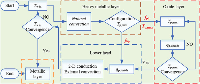
FIGURE 8. Flow chart of the coupled analysis method in MPCAP code.
At first, we assume that there is a known temperature in the pressure vessel inner wall surface, and then determine the heat transfer between the heavy metallic layer and oxide layer. When the maximum temperature of the oxide layer exceeds the melting point of the oxide layer, the heat transfer calculation in the molten oxide layer should be carried out. After obtaining the heat flux of the inner wall of the pressure vessel, it is used as an input parameter for two-dimensional conduction in the lower head, considering convection outside the vessel wall. Then the temperature of the inner wall surface of the pressure vessel is re-obtained. The convergence is judged and the calculation is repeated until the convergence limit is reached. Finally, the main parameters including the heat flux of the outer surface wall of the pressure vessel are obtained.
As an extension of AP600, AP1000 has a high degree of similarity to AP600 in all respects, with only the outer pressure vessel wall surface being closer to the cavity than AP600 in terms of IVR-ERVC effectiveness assessment. Both INEEL (Rempe et al., 1997) and ERI (Esmaili And Khatib-Rahbar, 2004) have carried out the studies on three-layer molten pool configuration. However, no calculation results are available for point estimation calculation. This section uses the input parameters in the ERI study to carry out a point estimation calculation for a three-layer molten pool configuration in AP1000 calculates the average heat flux at the bottom of the heavy metallic layer, also compares the calculation results of code MPCAP with those of Zhang et al. (2010).
The study of ERI and the study of Zhang et al. have used different heat transfer correlations for molten pools in AP1000. The study of ERI does not consider heat transfer from the oxide layer to the heavy metallic layer, while the study of Zhang et al. considers heat transfer from the oxide layer to the heavy metallic layer.
In this verification calculation, the code MPCAP uses the same heat transfer correlations as the study of ERI to calculate the heat transfer from the oxide layer to the metallic layer and the heat transfer from the oxide layer to the heavy metallic layer. The other main input parameters are shown in Table 1.
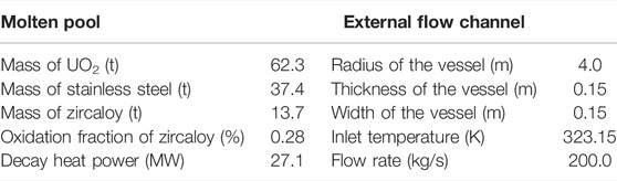
TABLE 1. Main input parameters in AP1000 verification calculation.
The results of the AP1000 three-layer molten pool configuration verification focused on heat flux in the outer surface wall of the pressure vessel wall, comparing the values calculated by code MPCAP with those calculated by the study of Zhang et al. The heat flux through pressure vessel wall is shown in Figure 9. When the heat transfer from the oxide layer to the heavy metallic layer is not considered, meaning that there is no heat transfer between the oxide layer and heavy metallic layer, the calculated values of code MPCAP in the inner wall surface is close to the results of the study of Zhang et al. When the heat transfer from oxide layer to heavy metallic layer is considered, the heat flux in the bottom region is higher. Due to a low CHF value in the bottom region, the heavy metallic layer shows an obvious focusing effect. In addition, the phenomenon of the focusing effect cannot be alleviated even by considering the effect of two-dimensional conduction.
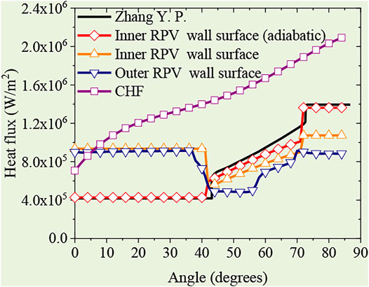
FIGURE 9. Heat flux of inner RPV wall surface in AP1000 verification calculation.
The results of the AP1000 three-layer molten pool configuration verification show that code MPCAP is able to predict the heat flux distribution. The heat transfer from the oxide layer to the heavy metallic layer exacerbates the focusing effect in the heavy metallic layer but reduces the heat flux in the metallic layer. The CHF value in the bottom area of the heavy metallic layer is low, and therefore, there is a risk of failure. The heat transfer from the oxide layer to the heavy metallic layer needs to be considered in the effectiveness assessment of IVR-ERVC.
Investigations on heat transfer in the thick lower heavy metallic layer are scarce, which have been conducted in this study for the IVR-ERVC adopted in research reactors. The main conclusions are presented as follows:
(1) The heat transfer in the molten pool has obvious influences on molten pool configuration. In this study, an improving lumped parameter method has been used to judge molten pool configuration. On this basis, a coupled analysis code MPCAP has been developed, which is based on the coupled simulation of natural convection inside a molten pool, two-dimensional conduction in the lower headwall, and convection outside the reactor vessel wall.
(2) The AP1000 three-layer molten pool configuration verification shows that code MPCAP is generally able to give reasonable predictions for the heat transfer in the molten pool.
The original contributions presented in the study are included in the article/Supplementary Material; further inquiries can be directed to the corresponding author.
JD and other authors have made all contributions to this manuscript.
This work in this paper was supported by the National Key R&D Program of China (Grant number: 2018YFB1900100).
The authors declare that the research was conducted in the absence of any commercial or financial relationships that could be construed as a potential conflict of interest.
All claims expressed in this article are solely those of the authors and do not necessarily represent those of their affiliated organizations, or those of the publisher, the editors, and the reviewers. Any product that may be evaluated in this article, or claim that may be made by its manufacturer, is not guaranteed or endorsed by the publisher.
Cao, Z., Liu, X., and Cheng, X. (2015). A Two Dimensional Approach for Temperature Distribution in Reactor Lower Head During Severe Accident. Ann. Nucl. Energy 85, 467–480. doi:10.1016/j.anucene.2015.04.042
Cummins, W. E., Corletti, M., and Schulz, T. (2003). Westinghouse AP1000 Advanced Passive Plant[C]. Proc. ICAPP, 4–7.
RRDB. Database[EB/OL]. 2020, Available at: https://nucleus.iaea.org/RRDB/Reports/CategoryList.
Esmaili, H., and Khatib-Rahbar, M. (2004). Analysis of In-Vessel Retention and Ex-Vessel Fuel Coolant Interaction for AP1000[R]. US Nuclear Regulatory Commission. Washington, DC: Office of Nuclear Regulatory Research.
Gilbert, C. (1979). Nuclear Reactor Safety-A Review of the Rasmussen Report (WASH-1400): Sydney. Australian Nuclear Science and Technology Organisation.
Kymäläinen, O., Tuomisto, H., and Theofanous, T. (1997). In-Vessel Retention of Corium at the Loviisa Plant[J]. Nucl. Eng. Des. 169 (1-3), 109–130.
Li, Y. B., Tong, L. L., Cao, X. W., and Guo, D. Q. (2015). In-Vessel Retention Coolability Evaluation for Chinese Improved 1000 MWe PWR. Ann. Nucl. Energy 76, 343–349. doi:10.1016/j.anucene.2014.09.035
Liu, X., Luo, Y., Zhen, C., Guo, R., and Cheng, X. (2018). Safety Research of IVR-ERVC for Advanced Water Cooled Reactor. Energy 156 (AUG.1), 458–467. doi:10.1016/j.energy.2018.05.123
Luo, Y., Liu, X., and Cheng, X. (2018). In- and Ex-Vessel Coupled Analysis for In-Vessel Retention. Prog. Nucl. Energy 109 (NOV), 74–82. doi:10.1016/j.pnucene.2018.07.013
Luo, Y., Liu, X., and Cheng, X. (2019). IVR-ERVC Study of 1700 MW Class PWR Based on MAAP Simulation and Coupled Analysis. Ann. Nucl. Energy 126 (APR), 1–9. doi:10.1016/j.anucene.2018.11.003
Oh, S., and Kim, H. (2005). Proceedings: Evaluation of Uncertainties in Relation to Severe Accidents and Level-2 Probabilistic Safety Analysis, 7–9. Effectiveness of External Reactor Vessel Cooling (ERVC) Strategy for APR1400 and Issues of Phenomenological Uncertainties[C]//Workshop.
Rempe, J., Knudson, D., Allison, C., Thinnes, G. L., and Atwood, C. L. (1997). Potential for AP600 In-Vessel Retention Through Ex-Vessel flooding. Idaho: Lockheed Idaho Technologies Co., Idaho National Engineering.
Safety of Research Reactors (2016). Safety of Research Reactors[M]. Vienna, Austria: International Atomic Energy Agency.
Theofanous, T., Liu, C., Additon, S., Angelini, S., Kymäläinen, O., and Salmassi, T. (1997). In-Vessel Coolability and Retention of a Core Melt[J]. Nucl. Eng. Des. 169 (1-3), 1–48. doi:10.1016/s0029-5493(97)00009-5
Wang, J., Chang, H., Zheng, W., and Zhou, Z. (2010). In-Vessel Retention of Molten Core Debris for CAP1400[C]//18th International Conference on Nuclear Engineering. Two Park Avenue New York NY, USA: American Society of Mechanical Engineers Digital Collection, 569–575. doi:10.13182/NT08-A3924
Zhang, Y. P., Qiu, S. Z., Su, G. H., and Tian, W. X. (2010). Analysis of Safety Margin of In-Vessel Retention for AP1000. Nucl. Eng. Des. 240 (8), 2023–2033. doi:10.1016/j.nucengdes.2010.04.020
k Thermal conductivity, W/(m·K)
Q Volume power density, W/m3
r Radius, m
s Area, m2 Structure
ε Emissivity
σ Stefban–Boltzmann, W/(m2·K4)
b Bottom
dn Downward
in Inside
max Maximum
o Outside
side Sideward
up Upward
w Wall
Nu Nusselt number
q Heat flux, W/m2
T Temperature, K
δ Thickness, m
θ Angle, degree
V Volume, m3
cr Crust
h Heavy metallic layer
m Light metallic layer
mp Melting point
p Oxide pool
t Top
ves Vessel
s Structure
Keywords: IVR-ERVC, thick metallic layer, heat transfer in molten pool, numerical simulation, coupled analysis
Citation: Deng J, Zhu D, Luo Y, Sun H, Zhang M, Liu L, Xiang Q, Wu X, Xu Y and Xiong Q (2022) Coupled Analysis of Heat Transfer in a Molten Pool With Three-Layer Configuration. Front. Energy Res. 10:915450. doi: 10.3389/fenrg.2022.915450
Received: 08 April 2022; Accepted: 02 May 2022;
Published: 13 June 2022.
Edited by:
Yapei Zhang, Xi’an Jiaotong University, ChinaReviewed by:
Hongyang Wei, Harbin Engineering University, ChinaCopyright © 2022 Deng, Zhu, Luo, Sun, Zhang, Liu, Xiang, Wu, Xu and Xiong. This is an open-access article distributed under the terms of the Creative Commons Attribution License (CC BY). The use, distribution or reproduction in other forums is permitted, provided the original author(s) and the copyright owner(s) are credited and that the original publication in this journal is cited, in accordance with accepted academic practice. No use, distribution or reproduction is permitted which does not comply with these terms.
*Correspondence: Yuejian Luo, bHVvX3l1ZWppYW5AMTYzLmNvbQ==
Disclaimer: All claims expressed in this article are solely those of the authors and do not necessarily represent those of their affiliated organizations, or those of the publisher, the editors and the reviewers. Any product that may be evaluated in this article or claim that may be made by its manufacturer is not guaranteed or endorsed by the publisher.
Research integrity at Frontiers
Learn more about the work of our research integrity team to safeguard the quality of each article we publish.