- 1Alpha ESS Co., Ltd., Nantong, China
- 2School of Electrical Engineering, Nantong University, Nantong, China
Power systems would face issues in system frequency stability when high scales of variable renewable energy generation are integrated in them. Battery energy storage systems (BESSs) with advanced control capability and rapid control response have become a countermeasure to solve the issues in system frequency stability. This research addresses a flexible synthetic inertial control strategy of the BESS to enhance the dynamic system frequency indices including the frequency nadir, settling frequency, and rate of change of the system frequency. To this end, the control loops based on the frequency excursion and rate of change of the system frequency are implemented into the d-axis controller of the BESS. The adaptive control coefficient of both control loops could be adjusted according to the instantaneous state of charge (SOC) so that it can inject more power to the grid at a higher SOC. The benefits of the proposed combined inertial control strategy are investigated with various sizes of disturbance and SOCs of the BESSs. Results successfully illustrate that the proposed combined inertial control strategy of the BESS is capable of enhancing the system frequency stability so as to promote variable renewable energy accommodation.
Introduction
As air pollutants and energy shortage have become significant around the world, variable renewable energy with characteristics such as sustainability and low/zero pollution, which includes wind power generation and photovoltaic power generation, is broadly applied to the electric power grid (Ackermann, 2012; Xiong et al., 2020). This growing trend, however, has raised security challenges on the power gird, e.g. frequency stability, voltage stability, and dynamic supporting capability issues (Xiong et al., 2022; Huang et al., 1109; Machowski et al., 2008). Variable renewable energy units connect to the electric power grid through power electronic devices in order to achieve advanced control capability such as maximum power point tracking operation (MPPTO) and decoupled control between the active power and reactive power (Ajjarapu et al., 2010; Yang et al., 2018). However, the units of variable renewable energy are limited in providing the dynamic frequency support capability including inertial response and primary frequency regulation (Kim et al., 2019a; Yang et al., 2022). This is because these units are decoupled to the system frequency and operate in MPPTO; as a result, the dynamic system frequency indices (DSFIs) including the frequency nadir, maximum rate of change of the system frequency, and settling frequency become worse (Lee et al., 2016; Dreidy et al., 2017). With increasing penetration levels of renewable power generation, this phenomenon becomes more severe that the underfrequency load shedding relays might be activated to avoid system frequency collapse due to the larger frequency nadir and maximum rate of change of the system frequency (Concordia et al., 1995; Ye et al., 2019). Frequency instability has become an issue that needs to be solved urgently.
The use of battery energy storage systems (BESSs) can be a feasible solution for enhancing the DSFIs because BESSs have rapid control response, advanced control capability, and bidirectional regulation capability (Zhao et al., 2015; Kim et al., 2019b). Mercier et al. (2009) suggested a control strategy of a BESS to provide frequency regulation with the purpose of minimizing the use of the BESS. In another study (Ma et al., 2017), the authors suggested that the SOC of the BESS should be retained within a stable range to avoid unexpected damage when performing frequency regulation. To address such limitations, an SOC feedback control strategy is suggested in the study by Stroe et al. (2017) and Shim et al. (2018) to avoid overcharging/discharging of the BESS. The authors of another study (Obaid et al., 2020) suggested a hierarchical control strategy of the BESS to provide frequency regulation capability; however, the control coefficient is fixed, which might limit the benefits of improving the DSFIs and result in overcharging of the SOC.
To solve the issue of reduction in the inertia time constant and capability of the primary frequency regulation when a large amount of renewable power generation is integrated in a power grid, this study addresses an SOC-based flexible synthetic inertial control strategy of the BESS with the aim of improving the DSFIs. To do this, the control loops based on the frequency excursion and df/dt are applied to the controller of the BESS. The adaptive control coefficient of both control loops is adjusted according to the instantaneous SOC so as to inject more active power to the grid at a higher SOC. Based on the EMTP-RV (electromagnetic transient program restructured version) simulator, the benefits of the proposed flexible synthetic inertial control strategy are explored under various sizes of disturbance and SOCs of the BESS.
Frequency Regulation of a Synchronous Generator
If a severe disturbance happens in a power grid, the synchronous generators inherently release their rotational energy to counterbalance the power deficit as inertia response (IR) so that the system frequency declines. The system inertia time constant determines the initial df/dt (Kim et al., 2019c); after that, the synchronous generators with primary frequency regulation (PFR, governor response) increase their mechanical input power to arrest the frequency decay and stabilize the dynamic system frequency; the control coefficient of the PFR determines the frequency nadir (fnadir) and settling frequency (Tto, 2010); then, the synchronous generators with secondary frequency regulation (SFR) increase their mechanical input power further to remove the frequency error, as illustrated in Figure 1. The processes of the IR and PFR can be represented as in the following equations:
where Hsys, fsys, and RSG are the system inertial time constant, system frequency, and control coefficient of the PFR, respectively. ΔPin, SG and ΔPdroop, SG are the power variation of the synchronous generator during IR and PFR, respectively. Δf is the system frequency excursion.
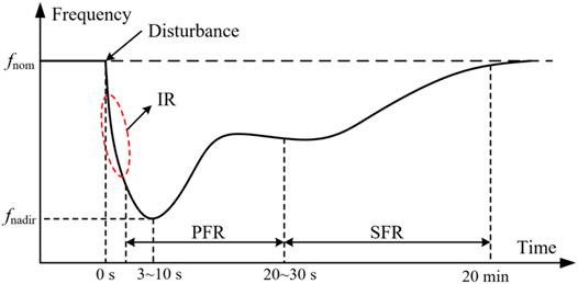
FIGURE 1. Frequency regulation strategies of a synchronous generator (Tto, 2010).
Control of the BESS
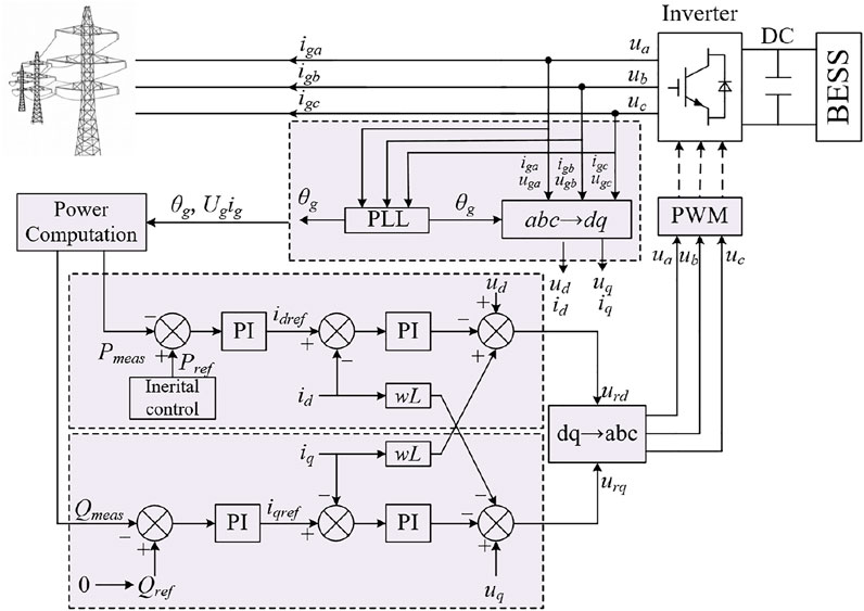
As illustrated in Figure 2, the grid voltage-oriented vector control scheme is implemented in the BESS to achieve decoupled control between the d-axis and q-axis by adjusting the currents of the d-axis and q-axis (Wu et al., 2017). The d-axis component and q-axis component focus on regulating the active power and reactive power injected to the electric power grid, respectively. The inertial control strategy generates the active power reference for the outer power controller of the d-axis. Furthermore, as shown in Figure 2, a phase-locked loop is used to detect the grid voltage and angle frequency in order to passively synchronize the BESS with the electric power grid.
Proposed Combined Inertial Control Strategy of the BESS
Influences of the Large-Scale Variable Renewable Power Generation Penetrated Power System on the Dynamic System Frequency Indices
The inertia time constant of a synchronous generator can be represented as (Kundur, 1994).
where JSG and ωSG are the moment of inertia and rated rotational speed of the synchronous generator, respectively. HSG and SSG are the inertia time constant and capacity of the synchronous generator, respectively.
When large scales of variable renewable power generation (wind power and photovoltaic power) are integrated, the equivalent inertia time constant of the power system can be rewritten as
where JRE and ωRE are the moment of inertia and rated rotational speed of the variable renewable power generation, respectively. SRE is the capacity of the variable renewable power generation.
The control coefficient for the governor response of the synchronous generator is represented as
The control coefficient of the governor response in per unit (the base value is SSG) is represented as
In a large scale of variable renewable power generation integrated power system, the equivalent control coefficient of governor response with a base value of SSG + SRE can be expressed as
During the traditional control logic, the photovoltaic power generation and wind power generation units are operating in MPPTO, so they are unable to participate in inertia and governor responses. In Eq. 4, there are two components in the molecule, which are the components of the synchronous generators and variable renewable energy units, respectively. Once the variable renewable energy units are unable to provide inertia control and primary frequency responses, the molecule becomes small so that the equivalent inertia constant becomes weak. Similar to (4), the denominator of (7) becomes small so that the control coefficient becomes large, and furthermore, the primary frequency regulation capability becomes weak. As a result, the dynamic indices of the system frequency including maximum df/dt, frequency nadir, and settling frequency become worse. This phenomenon becomes severe with increasing penetration of the renewable power generation.
Inertial Control Strategy of the BESS
As mentioned above, the BESS has advanced control capability and rapid control response; due to the use of power electronic devices, it would become a countermeasure to solve the issues in system frequency stability. This implies that the BESS can inject additional power to the grid or absorb the power from the grid when the BESS is in the discharging mode or charging mode.
To strengthen the frequency stability, a combined inertial strategy including the rate of change of the system frequency (df/dt) control loop and frequency deviation (Δf) control loop is implemented in the d-axis of the BESS, as shown in Figure 3.
As studied in by Hwang et al. (2016), in the initial period of disturbance, df/dt has the maximum value while Δf is almost zero, so the df/dt control loop is dominant for supporting the dynamic frequency; as time goes on, df/dt decays to zero and while Δf becomes maximum value at the frequency nadir, so the Δf control loop is dominant for supporting the DSFIs.
As shown in Figure 3, the output of the top control loop (ΔPin), which emulates the inertia response of the synchronous generator, is able to be written as
The output of the bottom control loop (ΔPdroop), which emulates the droop control of a synchronous generator, can be expressed as
where Δf and fnom are the system frequency excursion and the rated frequency represented in per unit, respectively.
During the inertial control period, the injected power (PBESS) from the BESS to the frequency drop can be represented as
There are two components in Eq. 10, which are the outputs of the df/dt control loop and frequency deviation control loop. The discharging mode is taken as an example; the signs of df/dt and frequency deviation are negative, so the negative sign is included in Eq. 10; the BESS can feed the power to the grid with a decreasing SOC, which is defined as the ratio of the instantaneous charge to the total charge in a fully charged state. The BESS retains the stable operation of the SOC, and this means that the SOC should be betweeen SOCmax and SOCmin (Ma et al., 2017). The incremental power of the BESS depends on the control coefficients (Kin and Kdroop) in Eq. 10. Thus, to improve the inertial control capability, when designing the control coefficients, the df/dt control loop and Δf control loop should be considered (See in Figure 4).
where SOC minus SOCmin means the potential for inertial control; K0 is the adjustable factor for the inertial control strategy of the BESS.
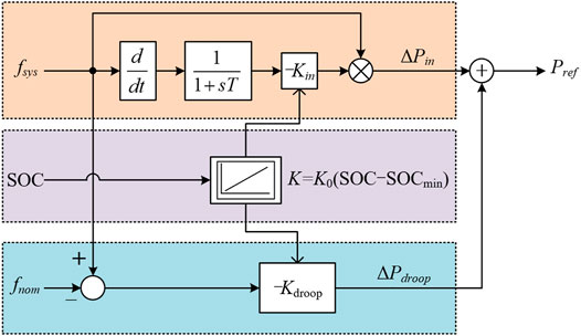
FIGURE 4. Proposed combined inertial control strategy of the BESS with an adaptive control coefficient.
In Eq. 11, there are two characteristics of the proposed control coefficient. The first characteristic is that the control coefficient increases with the SOC so as to flexibly utilize the capability of the BESS. The second characteristic is that the control coefficient decreases with the SOC; when SOC= SOCmin, the control coefficient is zero, so the BESS would not feed the active power to the power grid; thus, the SOC would not decrease below SOCmin and further prevent the BESS from overdischarging. The control coefficients in Eq. 11 can be used for the df/dt control loop and Δf control loop; thus, the proposed combined inertial control strategy of the BESS employing the adaptive control coefficient is able to improve the system frequency stability and prevent the BESS from overdischarging under low SOC conditions.
Model System
Figure 5 illustrates the modified IEEE 14-bus system integrated with variable renewable energy generations, which is used to explore the benefits of the proposed combined inertial control strategy of the BESS based on an EMTP-RV simulator. It includes an aggregated doubly-fed induction generator (DFIG)-based wind farm, photovoltaic power plant, and BESS, five traditional synchronous generators, and static loads. The total static load for all buses is set to 600.0 MW and 57.4 MVAr. All traditional synchronous generators are modeled as steam turbine generators by employing the IEEEG1 steam governor model (type B) with a droop setting of 5% (see Figure 6) (Yang et al., 2021). The capacity of the BESS is 5.0 MWh when connected to the power grid by a 5 MW DC/AC inverter with SOCs of 50 and 25%. The SOCmax and SOCmin are set to 90 and 10%, respectively.
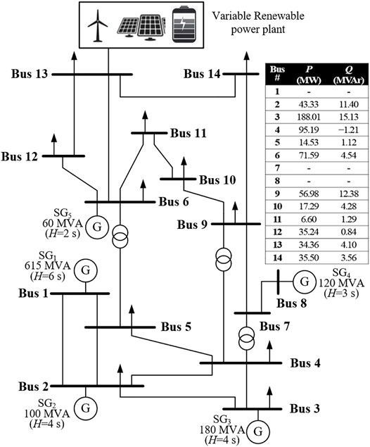
FIGURE 5. Modified IEEE 14-bus system embedded with a wind farm, photovoltaic power plant, and BESS.
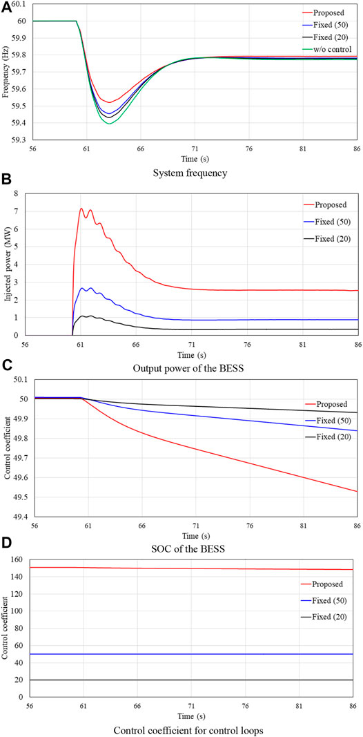
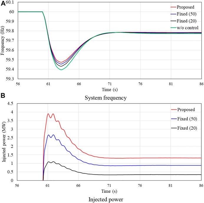
FIGURE 6. Results for case 1. (A) System frequency. (B) Output power of the BESS. (C) SOC of the BESS. (D) Control coefficient for control loops.
The wind farm and photovoltaic power plant are in the maximum power point tracking operation, and as a result, only the BESS participates in the inertial control of the frequency drop.
The dynamic system frequency indices (frequency nadir, maximum df/dt, and settling frequency) of the proposed combined inertial control strategy with an adaptive control coefficient are compared to that of the inertial control strategy with fixed coefficients (20 and 50) and without a control strategy. They are represented as “proposed,” “fixed (50),” “fixed (20),” and “w/o control” in the following explanations. In this section, since the system frequency indexes are related to the sizes of disturbance and SOCs of the BESS, the effectiveness of the proposed scheme is indicated by using case 1 and case 2 with various disturbances. The effectiveness of the proposed scheme is presented under SOCs of the BESS using case 1 and case 3.
Case 1: Disturbance of 60 MW With an Initial SOC of 50%
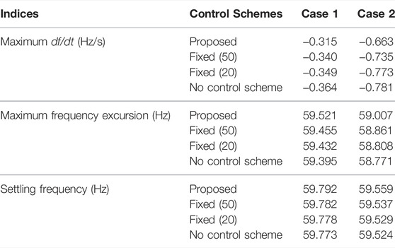
As displayed in Figure 6A and Table 1, if there is no control scheme implemented in the BESS, the dynamic system frequency indices (maximum df/dt, frequency nadir, and settling frequency) are −0.364 Hz/s, 59.395 Hz, and 59.773 Hz, respectively. When the BESS implemented the inertial control strategy with fixed control coefficients (20 and 50), the dynamic system frequency indices are improved to −0.349 Hz/s, 59.432 Hz, and 59.778 Hz, and −0.340 Hz/s, 59.455 Hz, and 59.782 Hz, respectively. This is because the BESS could feed a certain amount of active power to the grid to counterbalance the disturbance. When the BESS implemented the proposed inertial control strategy with an adaptive control coefficient, they are improved to −0.315 Hz/s, 59.521 Hz, and 59.792 Hz, respectively, since more power is fed to the grid by employing the adaptive control coefficient in Eq. 11.
The peak values of the injected power from the BESS of the fixed control coefficients (20 and 50) are 1.1 and 2.7 MW, respectively. The values of the injected power from the BESS during the steady state are 0.5 and 0.9 MW, respectively (see Figure 6B). These are the reasons that the inertial control strategy with a fixed control coefficient can enhance the dynamic system frequency indices. With an increasing coefficient, the benefits of improving the dynamic frequency indices become better. In the proposed inertial control strategy with an adaptive coefficient, the peak value of the injected power and value during the steady state are 7.1 and 3.6 MW, respectively. As a result, the reduction in the SOC of the proposed inertial control strategy is larger than that of other strategies, as illustrated in Figure 6C.
Case 2: Disturbance of 120 MW With an Initial SOC of 50%
Compared with case 1, a severe disturbance is employed to explore the performance of the proposed inertial control strategy of the BESS.
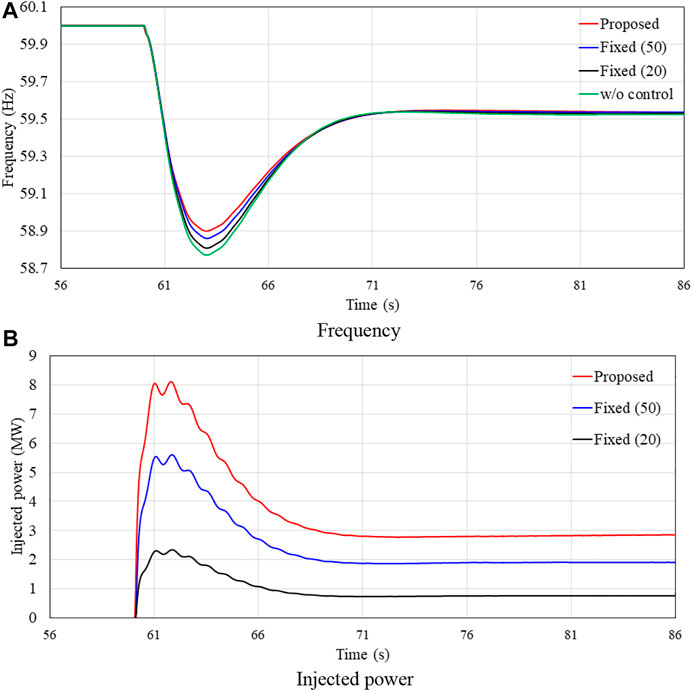
The dynamic system frequency indices of “w/o” are −0.781 Hz/s, 58.771 Hz, and 59.524 Hz, respectively, which become worse due to the severe power deficient, as shown in Figure 7. When the BESS implemented the fixed control coefficient inertial control strategy, the injected powers of the BESS increase to 2.2 and 5.9 MW and then decrease to 0.9 and 2.0 MW; as a result, the dynamic system frequency indices are improved to −0.773 Hz/s, 58.808 Hz, and 59.529 Hz, and −0.735 Hz/s, and 58.861 Hz, and 59.537 Hz, respectively. When the BESS implemented the adaptive control coefficient inertial control strategy, the injected power of the BESS increases to 14.2 MW and then decreases to 5.6 MW; as a result, the dynamic system frequency indices are improved to −0.663 Hz/s, 59.007 Hz, and 59.559 Hz, respectively.
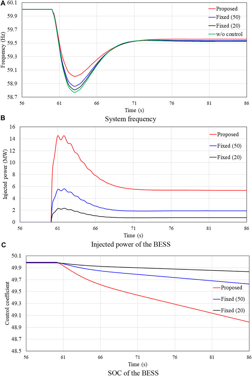
FIGURE 7. Results for case 2. (A) System frequency. (B) Injected power of the BESS. (C) SOC of the BESS.
Compared with those of case 1, the proposed synthetic inertial control strategy is able to improve the dynamic system frequency indices because of the increased df/dt and frequency excursion (see Table 1). Thus, the proposed synthetic inertial control is adaptive to the sizes of the disturbance.
Case 3: Initial SOC of 25%
Figure 8 and Figure 9 illustrate the simulation results when the BESS is with a low initial SOC of 25% under various sizes of disturbances. Compared to case 1 and case 2, due to the low initial SOC, even though the adaptive control coefficient become low compared to that of case 1 and case 2, the proposed inertial control strategy with an adaptive control coefficient could improve the dynamic system frequency indices. In a small disturbance, compared to the fixed control coefficient strategy, the indices are improved to −0.341 Hz/s, 59.474 Hz, and 59.785 Hz, respectively (see Figure 8). In addition, the dynamic indices are increased to −0.713 Hz/s, 58.900 Hz, and 59.540 Hz, respectively (see Figure 9). Consequently, the proposed synthetic inertial control strategy is able to improve the frequency stability even in a low initial SOC situation.
Conclusion
To solve the frequency stability issue when a large amount of renewable power generation is integrated in a power grid, this study addresses an SOC-based flexible synthetic inertial control strategy of the BESS to improve the dynamic system frequency indices. To do this, the control loops based on the frequency excursion and df/dt are implemented into the controller of the BESS. The adaptive control coefficient of both control loops is adjusted according to the instantaneous SOC so as to inject more active power to the grid at a higher SOC. The control coefficient is a linear function of the SOC, which is easy to implement. The benefits of the proposed combined inertial control strategy are investigated with various sizes of disturbance and SOCs of the BESSs.
Simulations based on EMTP-RV clearly illustrate that the proposed synthetic inertial control strategy of the BESS is able to enhance the dynamic system frequency indices in terms of improving the maximum df/dt, frequency nadir, and settling frequency. With the increasing sizes of disturbance, the frequency excursion and df/dt become severe; consequently, the benefits for enhancing the dynamic frequency indices become better. In addition, the proposed synthetic inertial control strategy could enhance the dynamic frequency indices in a lower scenario.
Data Availability Statement
The raw data supporting the conclusions of this article will be made available by the authors, without undue reservation.
Author Contributions
FY, XS, RD, and YimX conducted the back ground research of the project. YimX and DL proposed the methodology of the project. DL, YieX and YimX completed the main theory and simulation content. FY, XS, and YieX completed the writing of the paper. The work was supported by the fund of FY, XS, RD, DL, and YimX.
Funding
This work was supported by the Technology Project of Alpha ESS Co., Ltd. (21ZH479).
Conflict of Interest
FY, XS, RD, and DL were employed by Alpha ESS Co., Ltd.
The remaining authors declare that the research was conducted in the absence of any commercial or financial relationships that could be construed as a potential conflict of interest.
Publisher’s Note
All claims expressed in this article are solely those of the authors and do not necessarily represent those of their affiliated organizations, or those of the publisher, the editors, and the reviewers. Any product that may be evaluated in this article, or claim that may be made by its manufacturer, is not guaranteed or endorsed by the publisher.
References
Ajjarapu, V., McCalley, J. D., Rover, D., Wang, Z., and Wu, Z. (2010). Novel Sensorless Generator Control and Grid Fault Ride-Through Strategies for Variable-Speed Wind Turbines and Implementation on a New Real-Time Simulation Platform. Ames, IA, USA: Ph.D. dissertationDept. Elect. Eng., Iowa State Univ.
Concordia, C., Fink, L. H., and Poullikkas, G. (1995). Load Shedding on an Isolated System. IEEE Trans. Power Syst. 10 (3), 1467–1472. doi:10.1109/59.466502
Dreidy, M., Mokhlis, H., and Mekhilef, S. (2017). Inertia Response and Frequency Control Techniques for Renewable Energy Sources: A Review. Rene. Sustain. Energy Rev. 69, 144–155.
Huang, J., Zhang, L., and Sang, S. Optimized Series Dynamic Braking Resistor for LVRT of Doubly-Fed Induction Generator with Uncertain Faults Scenarios. IEEE ACCESS. doi:10.1109/ACCESS.2022.3154042
Hwang, M., Muljadi, E., Park, J.-W., Sorensen, P., and Kang, Y. C. (2016). Dynamic Droop-Based Inertial Control of a Doubly-Fed Induction Generator. IEEE Trans. Sustain. Energy 7 (3), 924–933. doi:10.1109/tste.2015.2508792
Kim, J., Gevorgian, V., Luo, Y., Mohanpurkar, M., Koritarov, V., Hovsapian, R., et al. (2019). Supercapacitor to Provide Ancillary Services with Control Coordination. IEEE Trans. Ind. Appl. 55, 5119–5127. doi:10.1109/tia.2019.2924859
Kim, J., Muljadi, E., Gevorgian, V., and Hoke, A. F. (2019). Dynamic Capabilities of an Energy Storage-Embedded DFIG System. IEEE Trans. Ind. Appl. 55 (4), 4124–4134. doi:10.1109/TIA.2019.2904932
Kim, J., Muljadi, E., Gevorgian, V., Mohanpurkar, M., Luo, Y., Hovsapian, R., et al. (2019). Capability‐coordinated Frequency Control Scheme of a Virtual Power Plant with Renewable Energy Sources. IET Gener. Transm. Distrib. 13, 3642–3648. doi:10.1049/iet-gtd.2018.5828
Kundur, P. (1994). Power System Stability and Control Electric Power Research Institute. New York: McGraw-Hill.
Lee, J., Jang, G., Muljadi, E., Blaabjerg, F., Chen, Z., and Cheol Kang, Y. (2016). Stable Short-Term Frequency Support Using Adaptive Gains for a DFIG-Based Wind Power Plant. IEEE Trans. Energy Convers. 31 (3), 1068–1079. doi:10.1109/tec.2016.2532366
Ma, Y., Cao, W., Yang, L., Wang, F. F., and Tolbert, L. M. (2017). Virtual Synchronous Generator Control of Full Converter Wind Turbines with Short-Term Energy Storage. IEEE Trans. Ind. Electron. 64 (11), 8821–8831. doi:10.1109/tie.2017.2694347
Machowski, J., Bialek, J. W., and Bumby, J. R. (2008). “Frequency Stability and Control,” in Power System Dynamics: Stability and Control. 2nd ed. (Wiltshire, U.K.: Wiley).
Mercier, P., Cherkaoui, R., and Oudalov, A. (2009). Optimizing a Battery Energy Storage System for Frequency Control Application in an Isolated Power System. IEEE Trans. Power Syst. 24 (3), 1469–1477. doi:10.1109/tpwrs.2009.2022997
Obaid, Z. A., Cipcigan, L. M., Muhssin, M. T., and Sami, S. S. (2020). Control of a Population of Battery Energy Storage Systems for Frequency Response. Int. J. Electr. Power Energy Syst. 115, 1–8. doi:10.1016/j.ijepes.2019.105463
Shim, J. W., Verbic, G., Zhang, N., and Hur, K. (2018). Harmonious Integration of Faster-Acting Energy Storage Systems into Frequency Control Reserves in Power Grid with High Renewable Generation. IEEE Trans. Power Syst. 33 (6), 6193–6205. doi:10.1109/tpwrs.2018.2836157
Stroe, D.-I., Knap, V., Swierczynski, M., Stroe, A.-I., and Teodorescu, R. (2017). Operation of a Grid-Connected Lithium-Ion Battery Energy Storage System for Primary Frequency Regulation: A Battery Lifetime Perspective. IEEE Trans. Ind. Appl. 53, 430–438. doi:10.1109/tia.2016.2616319
Tto, J. H. (2010). Use of Frequency Response Metrics to Assess the Planning and Operating Requirements for Reliable Integration of Variable Renewable Generation; Tech. Rep. Berkeley, CA, USA: Ernest Orlando Lawrence Berkeley National Laboratory.
Wu, Z., Gao, D. W., Zhang, H., Yan, S., and Wang, X. (2017). Coordinated Control Strategy of Battery Energy Storage System and PMSG-WTG to Enhance System Frequency Regulation Capability. IEEE Trans. Sustain. Energy 8 (3), 1330–1343. doi:10.1109/tste.2017.2679716
Xiong, L., Liu, X., Liu, Y., and Zhuo, F. (2020). Modeling and Stability Issues of Voltage-Source Converter Dominated Power Systems: a Review. Csee Jpes. doi:10.17775/CSEEJPES.2020.03590
Xiong, L., Liu, X., Liu, H., and Liu, Y. (2022). Performance Comparison of Typical Frequency Response Strategies for Power Systems with High Penetration of Renewable Energy Sources. IEEE J. Emerg. Sel. Top. Circuits Syst. 12, 41–47. doi:10.1109/JETCAS.2022.3141691
Yang, D., Jin, Z., Zheng, T., and Jin, E. (2022). An Adaptive Droop Control Strategy with Smooth Rotor Speed Recovery Capability for Type III Wind Turbine Generators. Int. J. Electr. Power Energy Syst. 135. doi:10.1016/j.ijepes.2021.107532
Yang, D., Kim, J., Kang, Y. C., Muljadi, E., Zhang, N., Hong, J., et al. (2018). Temporary Frequency Support of a DFIG for High Wind Power Penetration. IEEE Trans. Power Syst. 33 (3), 3428–3437. doi:10.1109/tpwrs.2018.2810841
Yang, D., Sang, S., and Zhang, X. (2021). Two-Phase Short-Term Frequency Response Scheme of a DFIG-Based Wind Farm. Front. Energy Res. 9, 781989. doi:10.3389/fenrg.2021.781989
Ye, Y., Qiao, Y., and Lu, Z. (2019). Revolution of Frequency Regulation in the Converter-Dominated Power System. Renew. Sustain. Energy Rev. 111, 145–156. doi:10.1016/j.rser.2019.04.066
Keywords: variable renewable energy, synthetic inertial control strategy, BESS, power system control, dynamic frequency indices
Citation: You F, Si X, Dong R, Lin D, Xu Y and Xu Y (2022) A State-of-Charge-Based Flexible Synthetic Inertial Control Strategy of Battery Energy Storage Systems. Front. Energy Res. 10:908361. doi: 10.3389/fenrg.2022.908361
Received: 30 March 2022; Accepted: 19 April 2022;
Published: 25 May 2022.
Edited by:
Liansong Xiong, Nanjing Institute of Technology (NJIT), ChinaReviewed by:
Tingting Sun, Hefei University of Technology, ChinaZongbo Li, Xi’an Jiaotong University, China
Copyright © 2022 You, Si, Dong, Lin, Xu and Xu. This is an open-access article distributed under the terms of the Creative Commons Attribution License (CC BY). The use, distribution or reproduction in other forums is permitted, provided the original author(s) and the copyright owner(s) are credited and that the original publication in this journal is cited, in accordance with accepted academic practice. No use, distribution or reproduction is permitted which does not comply with these terms.
*Correspondence: Yiming Xu, eWltaW5neEBudHUuZWR1LmNu
 Feng You
 Xiuli Si1
 Yien Xu