 Fengqin Li1
 Lulu Zhai
 Baoling Cui
- 1State-Province Joint Engineering Laboratory of Fluid Transmission System Technology, Zhejiang Sci-Tech University, Hangzhou, China
- 2Zhejiang Institute of Mechanical and Electrical Engineering Co., Ltd., Hangzhou, China
Annular seals can induce fluid excitation forces that severely affect the stability of the pump rotor systems. In this paper, a transient computational fluid dynamic method with a mesh deformation technique is used to study the fluid excitation forces generated on the long annular seal caused by cylindrical whirls and conical whirls. The reliability of the method is verified by comparing the simulation results with the experimental results. The whirl motion, composed of cylindrical and conical whirls, is realized by the phase difference between the whirl movements at the annular seal inlet and outlet, and the effects of the phase difference and inlet preswirl on the fluid excitation forces are studied numerically. The results show that the fluid excitation forces significantly depend on the phase difference of the rotor whirl movement, and tangential force acts as a stabilizing force only when the phase difference approaches 45°. The tangential forces of the cylindrical whirl, the conical whirl and the form of cylindrical and conical combined whirl are sensitive to inlet preswirl, while the effect of inlet preswirl on the radial forces becomes obvious only when the rotor whirls in the form of combined whirls.
Introduction
Annular seals are key components in centrifugal pumps, mainly including impeller wear rings, interstage seals and balancing drum gaps, as shown in Figure 1, to reduce internal leakage and balance axial forces. However, the fluid within the annular clearance will generate fluid excitation forces, which can affect rotor vibration or cause the whirl instability of rotor systems (Brennen and Acosta, 2006). These phenomena seriously endanger the safe and stable operation of centrifugal pumps.
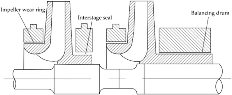
FIGURE 1. Typical annular seal structures of multistage centrifugal pump.
In view of the important influence of annular seals on the vibration and stability performance of rotor systems, many methods have been proposed to study the rotordynamic characteristics of annular seals. Childs (1983) first developed a rotordynamic force model for a turbulent annular seal based on the bulk-flow model raised by Black. Childs’ model showed that axial flow and inlet preswirl have significant effects on the fluid excitation forces of clearance flow. After that, Nelson (1985) derived the governing equations for compressible fluid in a tapered annular seal based on the bulk-flow model. The calculation results indicated that the prerotation around the seal inlet would dramatically increase cross-coupled stiffness. Zhai et al. (2018) also employed the bulk-flow model to calculate rotordynamic characteristics of a liquid annular seal with herringbone grooves on the rotor. The results showed that the seals with herringbone grooves have better sealing performance and provide better support actions and damping characteristics than the plain and spiral-grooved seals. Kanemori and Iwatsubo (1994a) performed theoretical and experimental method to investigate the rotordynamic characteristics of an annular seal. It was shown that annular seal with larger slenderness ratio tends to have negative direct stiffness. Recently, with the development of computer technology, the three-dimensional CFD method has been worked as an effective means to predict the rotordynamic characteristics of an annular seal. Subramanian et al. (2016) performed a quasi-steady CFD method to investigate rotordynamic characteristics of rotating labyrinth gas turbine seal with centrifugal growth. The results showed that the centrifugal growth primarily reduced cross-coupled stiffness and direct damping, and the influence increases with rotational speed. Ha and Choe (2014) investigated rotordynamic coefficients for an annular-type plain-gas seal by using a CFD method. It was found that the accuracy of the CFD method in predicting direct stiffness and cross-coupled stiffness have better improvements than that of the bulk-flow model. Li et al. (2015) adopted a transient CFD method based on single-frequency and multifrequency rotor whirling models to compare the rotordynamic characteristics of annular gas seals under one-dimensional whirling model, circular whirling model and elliptical whirling model. The results showed that the rotordynamic coefficients predicted by the transient CFD method with different rotor whirling models are in good agreement with the experimental results, and the six whirling models almost have the same magnitudes of all the rotordynamic coefficients. Xu et al. (2019) also adopted a transient CFD method with circular whirl to study the fluid excitation forces of clearance flow in canned motor reactor coolant pump. The results showed that the direct stiffness of the clearance flow is negative, and inlet preswirl of the auxiliary impeller has little effect on the cross-coupled stiffness. Jiang (2016) proposed a new transient CFD method based on rotor’s variable-speed whirl to obtain rotordynamic characteristics of pump seals. The results showed that the new transient method can keep the good accuracy of traditional transient method and meantime largely save the computational time.
The investigations on the above-mentioned annular seals are based on the condition of cylinder whirls, that is, the precession motions of the rotor are restricted to uniform lateral displacements. However, the parallel motion of a rotor is unlikely to occur in high-performance turbomachinery with large radial loads. These large loads such as impeller and inducer radial loads cause a rotor to flex, resulting in a tilted rotor in annular seals, which relates to conical whirls, i.e., shaft angular motions. Iino (Iino and Kaneko, 1980) found through experiments that the conical whirl has strong influences on fluid excitation forces acting on annular seals. Fenwick et al. (1982) first introduced conical whirls in short annular seals to calculate the fluid excitation forces. Then, Chen and Jackson (Chen and Jackson, 1985; Chen and Jackson, 1987) also calculated the fluid excitation forces caused by a large shaft conical whirl based on a short seal. The results showed that the rotordynamic characteristics vary dramatically under high misalignment conditions, especially if the direction of the perturbation is consistent with the minimum clearance. Zhang et al. (2016) explored the influence of tilting rotor on the characteristics of fluid-induced vibration for labyrinth seals, and it was concluded that all the stiffness coefficients and damping coefficients increase with the increase of tilt angle, and the tilting rotor decreases the stability of the rotor system. Subsequently, Wang (Wang et al., 2020) investigated the influences of shaft misalignment on the dynamic and static properties of an interlocking labyrinth seal. It was found that the effective damping raises as the misalignment angle increases, and the shaft misalignment reduces the leakage of the seal. San Andres (1993a) combined the bulk-flow model with the perturbation method to derive an analytical expression for calculating the rotordynamic characteristics of the conical whirl on a concentric short seal, then the author (Andres, 1993b) applied the method to study the dynamic force response of an annular seal under shaft misalignment conditions, and it was disclosed that misalignment at seal inlet enhances the supporting effect of the liquid film, while misalignment at seal outlet has the opposite effect. Scharrer et al. (1993) put forward a model for fixed tilt annular seals to research the effects of rotor misalignment on the rotordynamic characteristics of the seals. The results also revealed that a misalignment condition relative to the seal entrance produces a large force stiffening effect. Baskharone and Hensel (Baskharone and Hensel, 1991a; Baskharone and Hensel, 1991b) applied a complex three-dimensional virtually distorted finite element method to determine the rotordynamic characteristics for conical whirl motion, and it was concluded that the dynamic stability for the conical motions increases with the increasing rotor speed. Arghir and Frene (1997) calculated forces and moments in misaligned annular liquid seals based on the numerical integration of the perturbed averaged Navier-Stokes equations. The calculations indicated that the position of the tilting point has an obvious influence compared to that of the groove depth on forces and moments. Childs (1982) carried out an analysis for finite-length concentric annular seals with the bulk-flow model, and revealed that the rotordynamic coefficients caused by shaft axis angular displacement are important in the annular seals with large seal slenderness ratio, especially in submerged rotor pumps. Then, Simon and Frene (Simon and Frene, 1992a; Simon and Frene, 1992b) pointed out that as seal slenderness ratio increases, the rotordynamic coefficients caused by a conical whirl are of the same magnitude as those produced by a cylindrical whirl. Falco et al. (1986) also reported that force stiffness coefficients caused by shaft conical whirl are considerable in annular seals with slenderness ratio above 0.5, and it was found that the combined action of the shaft parallel motion and the shaft angular motion increases the seal equivalent stiffness and raises the critical speed of a multistage centrifugal pump.
In the present, the investigations of conical whirl on the misalignment annular seals are mainly based on the bulk-flow model, and the CFD method is seldom involved. In this paper, a transient CFD method based on mesh deformation technique is applied to study the fluid excitation forces generated by the conical and cylindrical whirls in a long annular seal. The reliability of the method is verified with an experiment. A whirl motion comprised of a cylindrical whirl and a conical whirl is introduced by giving the phase difference between the inlet and outlet of the annular seal. Then the effects of the phase difference and inlet preswirl on the fluid excitation forces are explored.
Numerical Calculation Method
Geometric Structure and Mesh
The annular seal studied in this paper is shown in Figure 2A, which is a liquid annular seal having the characteristics of smooth walls and a large slenderness ratio. The main geometrical dimensions and working conditions are listed in Table 1. The entire fluid field is meshed by structured grids, and the grids near the walls are refined, as shown in Figure 2B. The mesh independence of the annular seal is checked by comparing the leakage flowrates for different grid densities, as shown in Figure 3. It is observed that when the number of grids reaches 4.81 million, the leakage flowrate only changes a small amount with the further increase of the grid number. Therefore, considering the precision and efficiency of numerical calculations, the current number of annular seal grids of 4.81 million is selected for subsequent numerical research.
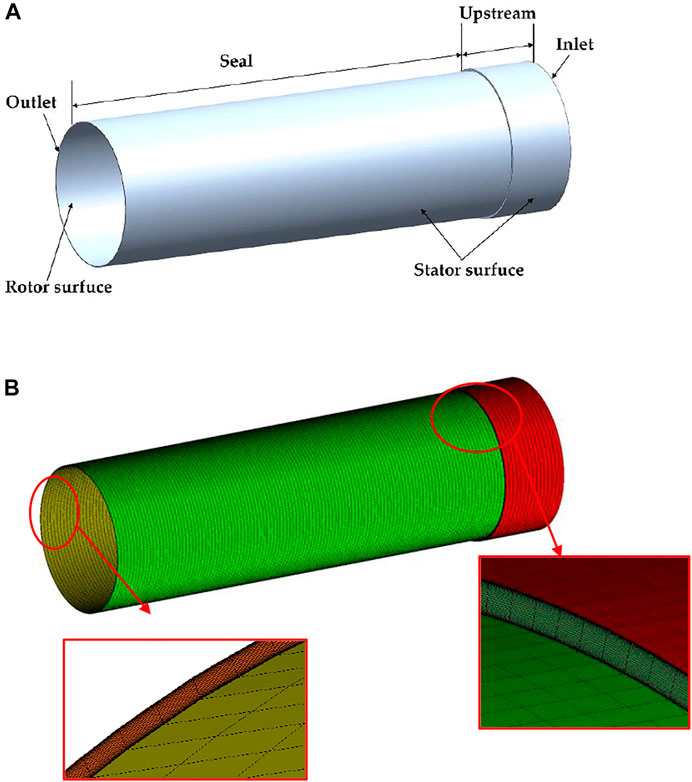
FIGURE 2. (A) The annular seal model and (B) grid.
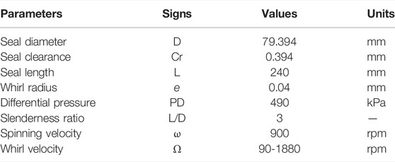
TABLE 1. The geometrical dimensions and operating conditions of the seal (Kanemori and Iwatsubo, 1994b).
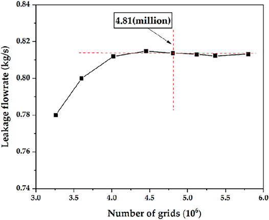
FIGURE 3. Mesh independence analysis.
Rotor Whirl Motions and Fluid Excitation Forces
The differential pressure between the annular seal inlet and outlet, and the rotation of the rotor cause the fluid inside the annular seal to be highly turbulent. Lomakin (1958) first pointed out that when there was a pressure difference between the seal inlet and outlet, the rotor would be subjected to a large restoring force, and at the same time, the fluid in the annular gap could induce rotor whirl. Then, Kanemori and Iwatsubo (Kanemori and Iwatsubo, 1994b) pointed out that the small whirl form of a long annular seal depends on the phase difference ψ between the seal inlet and outlet whirl movements, as shown in Figure 4, and the mathematical models of the inlet and outlet precessions are presented in Eq. 1.
When the phase difference ψ = 0°, it denotes a cylindrical whirl, as shown in Figure 5A. It means that the rotor axis of Z1Z′1 rotates around the stator axis of Z0Z′0 after the rotor is disturbed. The eccentric positions of the rotor at the seal inlet and outlet sections are the same, and the whirl model can be expressed as Eq. 2. For ψ = 180°, the rotor axis Z1Z′1 passes through seal half-length point M0 and rotates around the stator axis of Z0Z′0, as shown in Figure 5B. This perturbation motion is called a conical whirl. It is seen that the eccentric positions of the rotor at the seal inlet and outlet sections are opposite, and the whirl model is expressed as Eq. 3.
The fluid excitation forces caused by the small perturbations can be defined as a linearized model by introducing the rotordynamic coefficients, as shown in Eq. 4 (Childs, 1993). Fx and Fy are the components of fluid excitation forces in the static reference frame. The two expressions on the right side of the equation denote the fluid excitation forces generated by the cylindrical whirls and the conical whirls, respectively. After substituting Eqs 2, 3 into Eq. 4, according to the relationship between the static and moving reference frames, the radial forces Fr and the tangential forces Ft of the cylindrical whirls and the conical whirls can be expressed with the rotordynamic coefficients, as shown in Eqs 5, 6, respectively.
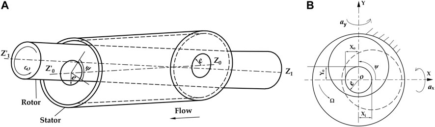
FIGURE 4. Phase difference between seal inlet and outlet movements. (A) schematic diagram of annular seal. (B) left view of the annular seal.
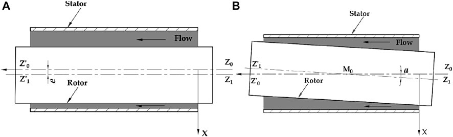
FIGURE 5. The rotor whirl motions. (A) cylindrical whirl. (B) conical whirl.
Transient CFD Solutions
The whirl motion of the rotor causes the fluid domain to change with time, which requires a mesh deformation technique to deal with. In the current work, the mesh deformation technique is realized through a subroutine connected with FLUENT solver to coordinate the movement of all nodes in the fluid domain. Figure 6 shows the movement of the grid nodes at any axial section of the annular seal. To clearly illustrate the method of grid movement, the seal clearance Cr has been exaggerated. In the figure, O1 denotes the eccentric position of the rotor after whirling from the concentric position O, and the movement distance is denoted by d (xd,yd). The node K (xK,yK) is an arbitrary point in the clearance, which is projected along a mesh line that connects one point F (xF, yF) on the rotor surface and the other point S (xS, yS) on the stator surface. After the rotor moves d, the new coordinates of F on the rotor are defined by Eq. 7.
The nodes on the stator stay stationary, and the movement distance of the node K in the seal clearance is determined by interpolation algorithm (Jiang, 2016; Li et al., 2018), Subsequently, the coordinates (xK1, yK1) of K1 in the clearance are achieved as shown in Eq. 8.
When the rotor is in concentric position, Sc is expressed by the coordinate (xK, yK) of K. When the rotor is in eccentric position, Sc can be expressed by the known coordinate (xK1, yK1) of K1, the movement displacement d of the rotor, and the initial angular displacement ϕ of K. Then substitute Sc into Eq. 8 to obtain next position of the node K1 in the clearance after the rotor moves.
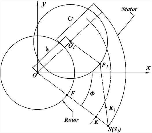
FIGURE 6. Diagram of the grid nodes moving.
When the rotor whirls cylindrically, the whirl radius along the axial direction is the same, that is, e, as shown in Figure 5A. The displacement (xd_cylinder, yd_cylinder) of the rotor in the cylindrical whirl is expressed as Eq. 2. As the rotor whirls conically, the rotor shaft rotates around the midpoint M0 of the seal and the red circle in Figure 7 represents the whirl locus. It is observed that the whirl radius along the axial direction is different, and the whirl radius is zero at the half-length of the seal. In other words, the intermediate node M on the rotor stays still. N1 is any node in the fluid domain, and N2 and N are the nodes on the stator and the rotor, respectively, which are obtained by the projection of N1 along the grid lines. When the rotor whirls conically, N1 represents the node N on the rotor after misalignment and a (ax, ay) denotes the axial misaligned angle. Therefore, the displacement of conical whirl (xd_cone, yd_cone) can be defined as a function of the axis coordinate of the grid node on the rotor and time, as shown in Eq. 9. The nodes on the rotor surfaces are determined to move based on Eqs 2, 9 for realizing the cylindrical whirl and conical whirl, respectively. These mathematical equations that control grid movement are loaded into FLUENT through a subroutine, and then the mesh in the fluid domain can be updated at each time step to obtain the optimum grid quality.
To verify the feasibility of the algorithm, the rotor is whirled from the concentric condition presented in Figure 8A (Figure 9A), to the eccentric condition, as illustrated in Figure 8B (Figure 9B), and it can be found that the maximum grid skewness raises from 0.056 to 0.43. The increase of grid skewness signifies the increase of grid distortion rate (the range of grid skewness is 0–1, and the value approaches one corresponding to poor quality) (ANSYS Fluent 16.0, 2011). However, there are no highly distorted grid units and negative volume cells in the whole seal domain, which presents the present mesh deformation technique can be used to simulate the whirling motion of long annular seals.
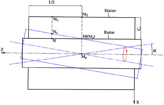
FIGURE 7. Mesh updating at radial clearance.
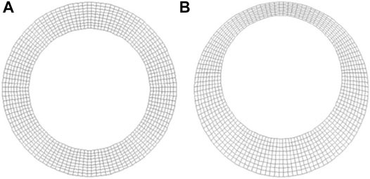
FIGURE 8. Circumferential view of an annular seal. (A) homocentric condition. (B) eccentric condition.
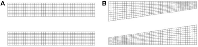
FIGURE 9. Axial view of an annular seal. (A) homocentric condition. (B) eccentric condition.
Fluent 16.0 is applied to solve the three-dimensional flow field of the long annular seal. The working fluid is water at a temperature of 25°C. The boundary conditions of the inlet and outlet are given as the total pressure (490 KPa) and the static pressure (0 MPa), respectively. The rotor surface and the stator surface are set as nonslip walls. The rotation speed of the rotor surface is given by DEFINE_ PROFILE, and the whirl speed of the rotor surface are determined through macro DEFINE_GRID_MOTION. The realizable k-ε turbulence model with an enhanced wall treatment is selected based on the Y plus less than 2.6. A first-order implicit scheme is employed to discretize the time term, and the rotor rotates one-degree as the time increment, i.e., 1.85e-4s. Second-order upwind schemes and central difference schemes are employed to discretize the convection term and the diffusion term, respectively. The pressure-velocity coupling is dealt with by the SIMPLE algorithm.
Experimental Verification
To validate the reliability of the transient CFD method based on the mesh deformation technique, the results of the CFD method are compared with the results of the experiment (Kanemori and Iwatsubo, 1994b) under the spinning speed of 900 rpm and the pressure difference of 490 kPa, as shown in Figure 10. V is inlet preswirl ratio denoting the ratio of the circumferential velocity of the fluid to the rotor surface velocity. It is found that the trends of the fluid excitation forces (Fr, Ft) of the cylindrical whirl and the conical whirl based on the CFD method match well with the experimental plots. The Fr values of the cylindrical whirl of the CFD method and the experiment are nearly the same when the nondimensional frequency is between −0.8 and 0.4. For the Ft values of the cylindrical whirl, the CFD method and the experiment are coincident at the nondimensional frequency range of 0.4–1.2. The maxi-mum errors of Fr and Ft of the cylindrical whirl based on the CFD method are 7.92 and 12.83%, respectively. The Fr values of the conical whirl of the CFD method are larger than those of the experiment in the whole range of the nondimensional frequency, while the Ft values of the CFD method are smaller than the experimental results. The maximum errors of Fr and Ft of the conical whirl based on the CFD method are 15.12 and 32.18%, respectively. The errors between the CFD method and the experiment are mainly caused by the uniform velocity and pressure boundary conditions used in the current CFD analysis, which is inconsistent with the practical non-uniform in the experiment. The results of the conical whirl of the CFD simulation are also compared with the results of the bulk-flow model and the experimental results (Kanemori and Iwatsubo, 1994b) under the spinning speed of 1,080 rpm and the pressure difference of 840 kPa, as depicted in Figure 11. It is found that the accuracy of the conical whirl based on the CFD method for predicting the tangential force is almost the same as that of the bulk-flow model. However, the prediction accuracy of the radial force by the conical whirl based on the CFD method is obviously higher than that of the bulk-flow model. Overall, the present transient CFD method has a reasonable accuracy in predicting the fluid excitation forces caused by the cylindrical whirl and the conical whirl in long annular seals, and can be used for further numerical studies.
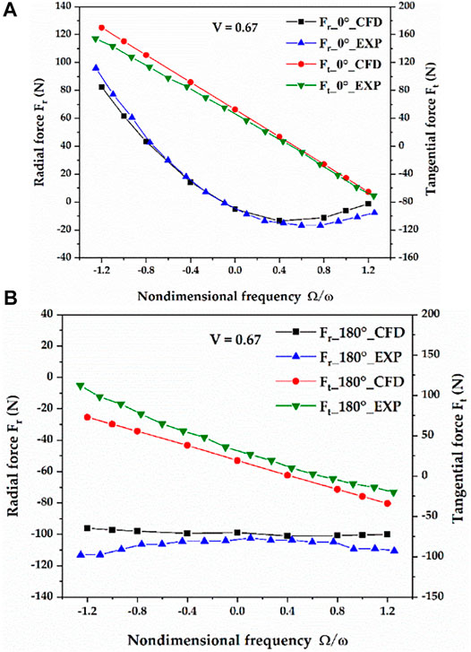
FIGURE 10. Comparison of the fluid excitation forces based on the CFD method with the experimental results. (A) cylindrical whirl. (B) conical whirl.
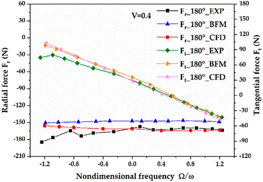
FIGURE 11. Comparison of the fluid excitation forces of the conical whirl based on the CFD method with the results of the bulk-flow method and the experimental results.
Figure 12 compares the rotordynamic coefficients predicted by the transient CFD method with the experimental results (Kanemori and Iwatsubo, 1994b) under various phase differences between the seal inlet and outlet. The phase difference between 0° and 180° represents that the rotor whirls in the cylindrical and conical combined mode. The relationship between the fluid excitation forces and the phase difference are defined as Eq. 10 (Kanemori and Iwatsubo, 1994b), and the rotordynamic coefficients of the combined mode are defined in Eq. 11. As shown in the figure, the direct stiffness coefficients and the cross-coupled damping coefficients of the CFD method under different phase differences nearly coincide with those of the experiment. The cross-coupled stiffness coefficients and the direct damping coefficients of the CFD method under different phase differences are larger than the experimental results, and the maximum errors are 18.2 and 31.03%, respectively. However, the variation trends of the predicted cross-coupled stiffness coefficients and direct damping coefficients under different phase differences match well with the experimental plots. Therefore, the transient CFD method has a good predictive capability for the rotordynamic characteristics of the long annular seal under different phase differences, which further verifies the feasibility of the method.
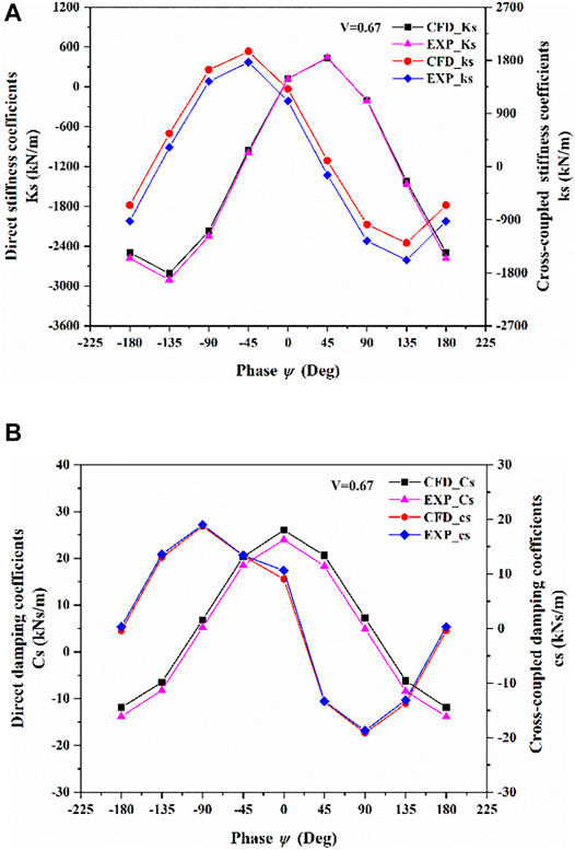
FIGURE 12. Comparison of the rotordynamic characteristics based on the transient CFD method with the experimental results. (A) stiffness coefficients. (B) damping coefficients.
Results and Discussion
Fluid Excitation Forces due to Positive Phase Difference Between the Seal Inlet and Outlet
Figure 13 shows the predicted fluid excitation forces when the phase at the seal outlet is ahead of the seal inlet, namely, when the phase difference ψ is positive. In Figure 13A, when ψ is 0°, i.e., a cylindrical whirl, in the range of Ω/ω from -1.2 to -0.1, the directions of the rotor displacement and Fr are the same, and Fr acts as an eccentric force to enlarge the radius of the whirl movement, which decreases the rotor critical speed. If ψ is 180°, i.e., a conical whirl, the displacement at the seal inlet due to misaligned angle is positive and Fr is negative. Therefore, Fr serves as a concentric force to decrease the whirl radius, which increases the rotor critical speed. However, since the displacement direction of the outlet is opposite to that of the seal inlet, Fr acts as an eccentric force at the seal outlet. When the rotor whirls with the cylindrical and conical combined mode, Ks is positive when ψ changes from 0° to 80° as shown in Figure 12A, which means Fr are negative. Therefore, Fr serve as concentric forces, while in the other phases, Fr serve as eccentric forces. In Figure 13B, the directions of Ft and the whirl movement are the same, and Ft serves as a destabilizing force in the region extending from the zero point (Ω/ω = 0) to the intersection of the Ft curve and the Ω/ω axis. If ψ is 0°, Ft is destabilizing in the range of Ω/ω from 0 to 0.55, which accelerates the whirl movement. The unstable region changes as ψ increases. If ψ increases to 45°, the unstable region of the forward whirl almost disappears. As ψ increases further, the intersecting point shifts to the negative direction of the Ω/ω axis, which causes the unstable region of the backward whirl to gradually increase. When ψ approaches 90°, and Ft plays the role of a destabilizing force within the range of Ω/ω from 0 to -0.65. As ψ approaches 135°, the Ft curve almost parallels to the Ω/ω axis due to the increasing of the unstable region of the backward whirl. When ψ reaches 180°, the unstable region of the backward whirl disappears, and there is an unstable region of the forward whirl that is in the range of Ω/ω from 0 to 0.4. In a word, Ft acts as a stabilizing force only when the phase difference approaches 45°, which restrains the forward whirl movement.
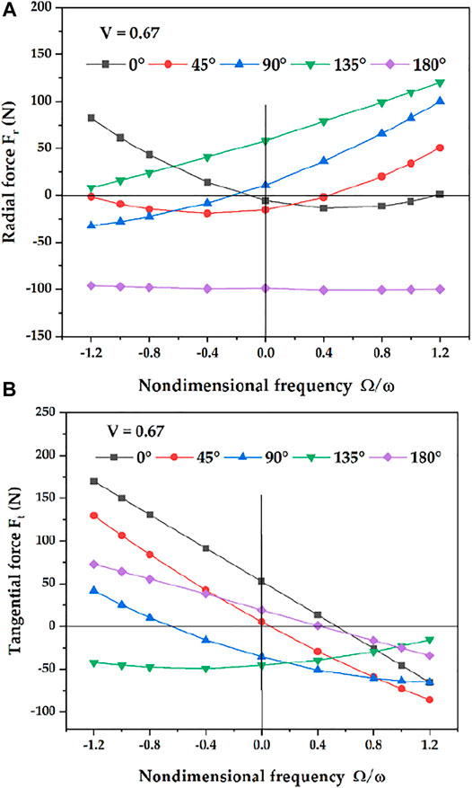
FIGURE 13. Fluid excitation forces due to positive phase difference. (A) radial force. (B) tangential force.
Fluid Excitation Forces due to Negative Phase Difference Between the Seal Inlet and Outlet
Figure 14 illustrates the case for the seal outlet being behind of the inlet, namely, when ψ is negative. In Figure 14A, when the rotor whirls with cylindrical and conical combined mode, Fr acts as an eccentric force at the seal inlet. If the rotor whirls cylindrically, Fr first decreases and then increases with the increasing whirl speed. The rotor whirls in the combined mode, and Fr decreases monotonically as the whirl speed increases, which is the opposite to that of the case of the positive phase difference. The influence of whirl speed on Fr becomes the minimum when the rotor whirls conically. As shown in Figure 14B, when ψ is between 0° and -90°, the unstable region of the forward whirl increases with the increase of ψ. When ψ reaches −90°, Ft acts as a destabilizing force in the range of Ω/ω from 0 to 1.2. As ψ increases to −135°, there is an unstable region of the forward whirl and an unstable region of the backward whirl, which are in the range of Ω/ω from 0 to 1.2 and −1.2 to −0.6, respectively. Furthermore, it can be seen from the figure that the relative magnitudes of the fluid excitation forces induced by the cylindrical whirls and the conical whirls are comparable. Therefore, the fluid excitation forces caused by conical whirls should be considered in long annular seals.
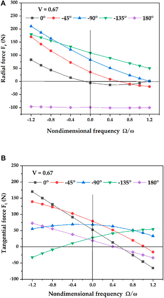
FIGURE 14. Fluid excitation forces due to negative phase difference. (A) radial force. (B) tangential force.
The Influence of Inlet Preswirl on the Fluid Excitation Forces
Figure 15 shows the influences of positive inlet preswirl and negative inlet preswirl on the fluid excitation forces with various phase differences. As shown in Figure 15B, all the Ft are sensitive to the inlet preswirl. The direction of the positive preswirl is the same as that of the forward cylindrical whirl and the forward conical whirl of the rotor, which tends to increase the destabilizing force Ft. In contrast, the direction of the negative preswirl is opposite to that of the rotation, which stabilizes the forward whirl. However, the negative preswirl promotes the backward whirl. The same influence of the preswirl on Ft can be found when the rotor whirls with the combined mode. As shown in Figure 15A, Fr is not sensitive to the inlet preswirl when ψ is 0° and 180°. However, the influence of the preswirl on Fr becomes obvious at the phase difference of 45°, 90° and 135°. This is because the radial force and the tangential force are coupled with phase difference when the rotor whirls in the form of the combined mode.
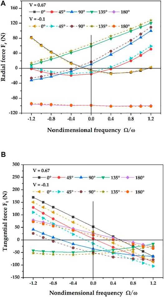
FIGURE 15. Influence of inlet preswirl on the fluid excitation forces. (A) radial force. (B) tangential force.
Conclusion
In the paper, the transient CFD method based on the mesh deformation technique is employed to research the fluid excitation forces generated on a long annular seal when the rotor whirls cylindrically and conically. The results of the CFD method are compared with the experimental results, and then the effects of phase difference between seal inlet and outlet and inlet preswirl on the fluid excitation forces are explored. The following conclusions are drawn.
1) The mesh deformation technique implemented through the user-defined subroutines can model the transient simulation of cylindrical whirls and conical whirls. The method can refresh the grids of the seal domain at every time step to obtain the optimum mesh quality after the grids are moved.
2) The transient CFD method has good accuracy in predicting the fluid excitation forces for cylindrical whirl and conical whirl, and the CFD method shows greater improvement than the bulk-flow method for predicting the radial force when the rotor whirls conically.
3) The tangential forces due to different negative phase differences all play the role of destabilizing forces to prompt the forward whirl, and the tangential force acts as a stabilizing force only when the phase difference approaches 45°. The rotor whirls with the phase in the range of 0° to 45°, the unstable region of the forward whirl gradually decreases with the increase of the positive phase, while gradually increasing with the increase of the negative phase.
4) The tangential forces of the cylindrical whirl, the conical whirl, and the form of the combined whirl are sensitive to inlet preswirl. There is no distinguishable influence of the preswirl on the radial force when the rotor whirls cylindrically and conically, while becoming obvious when the rotor whirls in the form of a combined whirl.
Data Availability Statement
The raw data supporting the conclusion of this article will be made available by the authors, without undue reservation.
Author Contributions
BC and ZZ conceived of the present idea. LZ and JG performed the validation. FL conducted the computations and wrote the present paper. All authors discussed the results and contributed to the final manuscript.
Funding
This research was funded by the National Natural Science Foundation of China (Grant No. 51976199 and No. 52076197), Key Research and Development Program of Zhejiang Province (Grant No. 2020C01027, Grant No. 2022C03036, and Grant No. 2022C01067), Zhejiang Province High-Level Talent Special Support plan (2019R51002) and Advanced Space Propulsion Laboratory of BICE and Beijing Engineering Research Center of Efficient and Green Aerospace Propulsion Technology (LabASP-2021-08).
Conflict of Interest
Author JG is employed by Zhejiang Institute of Mechanical and Electrical Engineering Co., Ltd.
The remaining authors declare that the research was conducted in the absence of any commercial or financial relationships that could be construed as a potential conflict of interest.
Publisher’s Note
All claims expressed in this article are solely those of the authors and do not necessarily represent those of their affiliated organizations, or those of the publisher, the editors and the reviewers. Any product that may be evaluated in this article, or claim that may be made by its manufacturer, is not guaranteed or endorsed by the publisher.
References
Andres, L. S. (1993b). Effect of Shaft Misalignment on the Dynamic Force Response of Annular Pressure Seals. Tribol. Trans. 36, 173–182. doi:10.1080/10402009308983146
Arghir, M., and Freˆne, J. (1997). Forces and Moments Due to Misalignment Vibrations in Annular Liquid Seals Using the Averaged Navier-Stokes Equations. J. Tribol. 119, 279–287. doi:10.1115/1.2833194
Baskharone, E. A., and Hensel, S. J. (1991a). Interrelated Rotordynamic Effects of Cylindrical and Conical Whirl of Annular Seal Rotors. J. Tribol. 113, 470–480. doi:10.1115/1.2920648
Baskharone, E. A., and Hensel, S. J. (1991b). Moment Coefficients of Incompressible-Flow Seals with Conically Whirling Rotors. Int. J. Mech. Sci. 33, 151–167. doi:10.1016/0020-7403(91)90064-a
Brennen, C. E., and Acosta, A. J. (2006). Fluid-Induced Rotordynamic Forces and Instabilities. Struct. Control Health Monit. 13, 10–26. doi:10.1002/stc.145
Chen, W. C., and Jackson, E. D. (1987). A Generalized Theory for Eccentric and Misalignment Effects in High-Pressure Annular Seals. A S L E Trans. 30, 293–301. doi:10.1080/05698198708981760
Chen, W. C., and Jackson, E. D. (1985). Eccentricity and Misalignment Effects on the Performance of High-Pressure Annular Seals. A S L E Trans. 28, 104–110. doi:10.1080/05698198508981601
Childs, D. W. (1982). Rotordynamic Moment Coefficients for Finite-Length Turbulent Seals, Proc. Of International Conference on Rotordynamic Problems in Power Plants. 371–378.
Childs, D. W. (1993). Turbomachinery Rotordynamics: Phenomena, Modeling, and Analysis. New York. John Wiley & Sons.
Childs, D. W. (1983). Finite-Length Solutions for Rotordynamic Coefficients of Turbulent Annular Seals. J. Lubr. Technol. 105, 437–444. doi:10.1115/1.3254636
Falco, M., Mimmi, G., and Mareno, G. (1986). Effects of Seals on Rotor Dynamics, Proceedings of the IFToMM Conf. 655–661.
Fenwick, J., Dijulio, R., Ek, M. C., Ehrgott, R., Green, H., and Shaolian, S. (1982). Linear Force and Moment Equations for an Annular Smooth Shaft Seal Perturbed Both Angularly and Laterally. NASA. Lewis Res. Cent. Rotordyn. Instab. Probl. High-Performance Turbomach., 130–146.
Ha, T. W., and Choe, B. S. (2014). Numerical Prediction of Rotordynamic Coefficients for an Annular-type Plain-Gas Seal Using 3D CFD Analysis. J. Mech. Sci. Technol. 28, 505–511. doi:10.1007/s12206-011-0830-3
Iino, T., and Kaneko, H. (1980). Hydraulic Forces Caused by Annular Pressure Seals in Centrifugal PumpsHigh-Performance Turbomachinery. NASA. Lewis Res. Cent. Rotordyn. Instab. Probl., 213–225.
Jiang, X. K. (2016). Transient CFD Simulation on the Flow Field and Dynamic Characteristics of Annular Seals [ Ph.D. Dissertation]. [Zhejiang]. Zhejiang Univ.
Kanemori, Y., and Iwatsubo, T. (1994b). Forces and Moments Due to Combined Motion of Conical and Cylindrical Whirls for a Long Seal. J. Tribol. 116, 489–498. doi:10.1115/1.2928871
Kanemori, Y., and Iwatsubo, T. (1994a). Rotordynamic Analysis of Submerged Motor Pumps : Influence of Long Seal on the Stability of Fluid Machinery. JSME Int. J. Ser. C, Dyn. control, robotics, Des. Manuf. 37, 193–201. doi:10.1299/jsmec1993.37.193
Li, Q., Zhang, S., and Xu, W. W. (2018). Analysis of Nonlinear Oil Film Force of Journal Bearing Based on 3D Transient Flow Field Calculation. J. Vib. Shock.37, 141–147.
Li, Z. G., Li, J., and Feng, Z. P. (2015). Comparisons of Rotordynamic Characteristics Predictions for Annular Gas Seals Using the Transient Computational Fluid Dynamic Method Based on Different Single-Frequency and Multifrequency Rotor Whirling Models. J. Tribol. 138, 011701. doi:10.1115/1.4030807
Lomakin, A. A. (1958). Calculating of Critical Speed and Securing of Dynamic Stability of High-Pressure Pump with Reference to Forces Arising in Seal Gaps. Energomashinostroenie 4, 5.
Nelson, C. C. (1985). Rotordynamic Coefficients for Compressible Flow in Tapered Annular Seals. J. Tribol. 107, 318–325. doi:10.1115/1.3261062
San Andres, L. (1993a). Dynamic Force and Moment Coefficients for Short Length Annular Seals. J. Tribol. 115, 61–70. doi:10.1115/1.2920987
Scharrer, J. K., Rubin, N., and Nelson, C. C. (1993). The Effects of Fixed Rotor Tilt on the Rotordynamic Coefficients of Incompressible Flow Annular Seals. J. Tribol. 115, 336–340. doi:10.1115/1.2921640–
Simon, F., and Frene, J. (1992a). Rotordynamic Coefficients for Turbulent Annular Misaligned Seals. Rotating Machinery-Dynamics., 207–222.
Simon, F., and Frêne, J. (1992b). Analysis for Incompressible Flow in Annular Pressure Seals. J. Tribol. 114, 431–438. doi:10.1115/1.2920902
Subramanian, S., Sekhar, A. S., and Prasad, B. V. S. S. S. (2016). Rotordynamic Characteristics of Rotating Labyrinth Gas Turbine Seal with Centrifugal Growth. Tribol. Int. 97, 349–359. doi:10.1016/j.triboint.2016.01.003
Wang, Y. F., Zhang, W. F., Pan, B., and Li, C. (2020). Effect of Shaft Misalignment on Dynamic and Static Characteristics of Interlocking Labyrinth Seals. Acta Aeronautica Astronautica Sinica 41, 123782.
Xu, R., Long, Y., Hu, Y. Y., Yin, J. L., and Wang, D. Z. (2019). Numerical and Experimental Research on the Fluid-Induced Forces of Clearance Flow in Canned Motor Reactor Coolant Pump. J. Eng. Gas. Turb. Power 141, 061021. doi:10.1115/1.4041756
Zhai, L., Zhenjie, Z., Zhonghuang, C., and Jia, G. (2018). Dynamic Analysis of Liquid Annular Seals with Herringbone Grooves on the Rotor Based on the Perturbation Method. R. Soc. open Sci. 5, 180101. doi:10.1098/rsos.180101
Zhang, W., Zhang, Y., Yang, J., and Li, C. (2016). Influence of Tilting Rotor on Characteristics of Fluid-Induced Vibration for Labyrinth Seals. J. Vibroeng 18, 5416–5431. doi:10.21595/jve.2016.17737
Nomenclature
a axial misaligned angle, radian
ax angular rotation around the x axis, radian
ay angular rotation around the y axis, radian
C, Ca direct damping coefficient, Ns/m
c, ca cross-coupled damping coefficient, Ns/m
e radius of whirl, mm
Fx fluid excitation force in the x direction, N
Fy fluid excitation force in the y direction, N
Fr radial force, N
Ft tangential force, N
K, Ka stiffness coefficient, N/m
k, ka stiffness coefficient, N/m
M, Ma direct added mass coefficient, kg
V inlet preswirl ratio
z the z coordinate of the grid node in the axial direction
ψ phase difference between the seal inlet and outlet whirling movements, degree
ε fluid excitation force of cylindrical whirl
α fluid excitation force of conical whirl
s fluid excitation force of cylindrical whirl and conical whirl combined mode
Keywords: long annular seal, transient CFD method, rotor whirl, fluid excitation forces, inlet preswirl
Citation: Li F, Zhai L, Cui B, Zhu Z and Guo J (2022) Investigation of Fluid Excitation Forces Induced by Cylindrical and Conical Whirls in a Long Annular Seal Using Transient CFD Methods. Front. Energy Res. 10:907945. doi: 10.3389/fenrg.2022.907945
Received: 30 March 2022; Accepted: 19 April 2022;
Published: 16 May 2022.
Edited by:
Mostafa S. Shadloo, Institut National des Sciences Appliquées de Rouen, FranceReviewed by:
Dan Sun, Shenyang Aerospace University, ChinaXi Chen, Southern University of Science and Technology, China
Copyright © 2022 Li, Zhai, Cui, Zhu and Guo. This is an open-access article distributed under the terms of the Creative Commons Attribution License (CC BY). The use, distribution or reproduction in other forums is permitted, provided the original author(s) and the copyright owner(s) are credited and that the original publication in this journal is cited, in accordance with accepted academic practice. No use, distribution or reproduction is permitted which does not comply with these terms.
*Correspondence: Lulu Zhai, emhhaWx1bHVAenN0dS5lZHUuY24=