 Qun Li1
 Jianhui Meng
94% of researchers rate our articles as excellent or good
Learn more about the work of our research integrity team to safeguard the quality of each article we publish.
Find out more
ORIGINAL RESEARCH article
Front. Energy Res., 05 May 2022
Sec. Smart Grids
Volume 10 - 2022 | https://doi.org/10.3389/fenrg.2022.907770
This article is part of the Research TopicIntelligent Operation and Control in Next Generation Urban Power GridView all 14 articles
With the increase of the penetration rate of wind power in the power grid, the high proportion of renewable energy and the high proportion of power electronic equipment in the power system will continuously reduce the inertia of the grid, and the frequency stability of the system will be seriously affected. The inertia of the system is an important parameter for system frequency regulation and stability calculation. For this reason, a virtual inertial control technology based on fuzzy logic control is proposed in this paper, which is used for wind turbines to participate in grid frequency regulation. In this method, based on power tracking, a fuzzy logic controller is designed to adjust the frequency adjustment coefficient adaptively, and fuzzy logic rules are used to optimize the power tracking curve online. Finally, by building a hardware-in-the-loop real-time simulation platform, the effectiveness of this method in providing system frequency support and improving the frequency response of the power grid is verified.
In recent years, with the result of increased new energy, the power grid has been moving toward a new power system with new energy sources as the mainstay. The traditional synchronous generators in power grids have better inertia and damping properties. As the high percentage of new energy and power electronic equipment gradually replace the traditional synchronous generators, the lack of inertia in the power system to support the grid is becoming apparent, and the frequency regulation capability available in the system is significantly reduced (Fang et al., 2018; Nguyen et al., 2019; Kheshti et al., 2020). Therefore, it is significant to study the importance of improving the inertia of the power system to support the frequency stability of the system while the power system is gradually moving toward low inertia.
China has abundant wind resources, and the installed wind capacity has grown exponentially. The replacement of conventional generating units with wind power reduces the effective inertia of the system, and the magnitude of inertia reflects the ability to prevent sudden changes in system frequency. Virtual inertia control techniques for improving the frequency stability of new energy systems are rapidly developing. The method of virtual inertia control technology used to improve the frequency stability of new energy systems is developing rapidly. In order to realize the inertial support of wind turbines to the system, Holdsworth et al. proposed the virtual inertia control of the variable speed wind turbines in 2004 (Holdsworth et al., 2004). It regulates the electromagnetic power in response to the frequency change of the grid and provides inertial support by varying the converter control strategy. The paper (Lalor et al., 2005) further proposed an additional frequency control scheme for wind turbines. The differential link is used to convert the rotational speed signal into an additional torque signal. After the system frequency drops, the rotational kinetic energy of the wind turbine is released to achieve the inertial response of the wind turbine. The paper (Chau et al., 2018) also introduced an inertial response to grid frequency by instantaneously releasing rotor kinetic energy, but did not fully analyze the control effect of the additional controllers. In (Wang et al., 2015), an artificial inertial control strategy is proposed. The kinetic energy is extracted by dynamically modifying the optimal power curve of the wind turbine. The kinetic energy is extracted by dynamically modifying the optimal power curve of the wind turbine. Yan et al. (2020) and Terazono et al. (2021) designed a synchronizer with multiple virtual rotating masses to improve the active power tracking performance and facilitate the inertial control of the synchronizer. But the problem of impaired power tracking has not been resolved. The paper (Liu et al., 2021) adopts a nonlinear virtual inertial control method based on a wind power integrated power system to provide the primary frequency support of the power grid. In (Wang and Tomsovic, 2018), a novel active power control framework was proposed to make the doubly-fed induction generator modify the reserve input under different operating modes. However, only inertia and primary frequency support are provided, and there are also deficiencies in the frequency response. Bao et al. (2021) and Ren et al. (2021) designs a hierarchical inertial control scheme that coordinates the active power output in the inertial control process between the wind turbine and the battery energy storage system to improve the frequency response of the system. There will also be excessive rotor speed deceleration and high-cost question.
With the rapid development of fuzzy logic and fuzzy theory in recent decades, its application research has achieved fruitful results. Using expert control experience, fuzzy logic control has better control characteristics for nonlinear and complex research objects, and has been widely and effectively applied in industrial process control, robotics, transportation, etc. (Tan et al., 2020; Oshnoei et al., 2021; Yap et al., 2021). The application of fuzzy logic control is also quite extensive in the control of new energy power generation. For example, literature (Miao et al., 2015) adopts fuzzy logic control for rotor speed recovery controller to achieve inertial control of rotor kinetic energy, but this method cannot adaptively control the control parameters for complex changing power grids. Athari and Ardehali (2016) and Karimi et al. (2020) developed a fuzzy logic controller to control the state of charge of the energy storage battery, which is still difficult to resist the disturbance of unknown parameters. The literature (Kerdphol et al., 2019) proposes a fuzzy logic inertial control method for grid frequency stability under high penetration conditions, which automatically adjusts virtual inertial constants according to active power and system frequency deviation to achieve a fast inertial response. In the literature (Long et al., 2021), a new control method combining fuzzy logic control and model predictive controller is proposed to effectively reduce the frequency deviation when dealing with large load changes. Therefore, in this paper, aiming at the low inertia system of new energy power electronic equipment, taking the wind turbine network system as the research object, this paper proposes a fuzzy logic controller to adaptively optimize the power tracking and enhance the frequency support and response capability of the system.
In order to solve the problem of the lack of inertia of the power system and the reduction of the system frequency support capacity caused by a high percentage of new energy sources on the grid, this paper proposes a virtual inertia control strategy for permanent magnet synchronous wind turbine based on the fuzzy logic method. This strategy has promising research significance, and its main contributions to the paper can be summarized as follows:
1) In this paper, according to the grid frequency deviation and frequency change rate, the fuzzy logic controller is designed with fuzzy logic, and the virtual inertial control strategy based on power tracking is optimized.
2) By combining the fuzzy controller with the optimized PMSG virtual inertia control, the self-adaptive adjustment of the system inertia is achieved to support the system frequency.
3) A hardware-in-the-loop real-time experimental platform based on RT-LAB is built to verify the effectiveness of the proposed method.
This paper takes the three-machine, nine-node system for grid-connected wind power generation as the test object, and is organized as follows. Firstly, Section 2 introduces the three-machine, nine-node system for grid-connected PMSG, and mathematically models the PMSG. Secondly, Section 3 analyzes two typical virtual inertia control techniques by analyzing the influence between wind turbines and system frequency stability. In Section 4, based on the previous analysis of virtual inertial control technology, the virtual inertial control strategy based on power tracking is optimized, and a virtual inertial control based on fuzzy logic control is proposed. The fuzzy logic rules are used to optimize the power tracking online, and the system inertia can be improved to enhance the frequency support capability of the system. Finally, in Section 5, a hardware-in-the-loop test platform is built based on a three-machine nine-node test system to verify the effectiveness of the proposed method.
The inertia in the traditional power grid mainly comes from the synchronous generator. With the integration of large-scale new energy into the power grid, the frequency regulation capability of the power grid in low inertia operation is reduced, and the system stability performance is poor. In order to better study the stability of the new energy grid system, build the test system as shown in Figure 1.
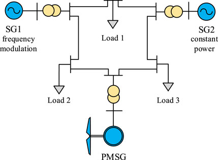
FIGURE 1. 3-machine 9-node networking system topology.
It shows the topology of the constructed 3-machine 9-node networking system. The system includes three constant impedance loads and transformers, frequency modulation unit SG1, constant power unit SG2 and PMSG wind turbine.
Wind turbine based on permanent magnet synchronous generator adopts three-blade wind turbine and multi-pole low-speed permanent magnet synchronous generator with the same speed as the wind turbine. The PMSG stator is connected to the power grid through the full power converter, and the grid-side converter realizes the grid-connected operation of the wind turbine and ensures the quality of the power delivered by the turbine. The output characteristics of the wind turbine depend entirely on the control system design of the inverter and the wind speed variation.
Figure 2 shows the structure of the permanent magnet direct drive wind turbine. The PMSG wind turbine has few control loops and has high operational reliability and efficiency. Define the PMSG stator voltage as Us, Is is the stator current, Ψf is the excitation flux linkage, and the potential E. Then E can be expressed as:
where ωr is the PMSG rotor angular velocity.
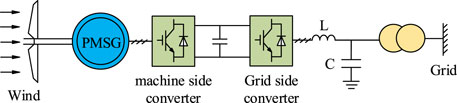
FIGURE 2. Permanent magnet direct drive wind turbine.
The flux linkage and the electromagnetic torque of the PMSG in the two-phase synchronously rotating dq coordinate system are
where Ld and Lq are the equivalent inductance of stator windings on the d-axis and q-axis, respectively, pn is the number of PMSG pole pairs, Te is the mechanical torque.
The stator voltage of PMSG in the dq coordinate system can be expressed as
Through the above formula, the output power and electromagnetic torque of the stator side of PMSG in the dq coordinate system can be expressed as
where Ps and Qs are the output active power and reactive power of the stator side, respectively. usd, usq, isd, and isq are the voltage and current of the stator at dq axis respectively. ψsd and ψsq are the flux linkage component of the dq axis.
The PMSG rotor structure is usually symmetrical, and Ld = Lq can be set. Then Eq. 7 can be simplified as
As wind power is integrated into the grid, the lack of effective support for the system poses a threat to grid frequency stability. The inertia of the system is an important characteristic of the grid frequency stability. In a conventional grid, when the output power of the system is not equal to the load consumption, a power deviation is generated, which is compensated by the rotational kinetic energy stored in the rotor of a conventional synchronous generator, resulting in a lower SG speed and a deviation of the system frequency from the rated value.
For traditional synchronous generator sets, when the output power of the system is not equal to the load consumption, the deviation is compensated by the rotational kinetic energy Ek stored in the SG, and the deviation ΔEk can be expressed as
where ΔP is the power deviation between the output power and the load consumption; ωm and ωg are the mechanical angular frequency and electrical angular frequency of SG, respectively; J is the rotational inertia; p is the polar logarithm, and when p is 1, Eq. 9 can be expressed as
When there are n SGs in the system, Eq. 10 can be expressed as
where Jt is the total rotational inertia of the system.
In order to make the wind turbine inverter simulate the rotational inertia of the conventional synchronous generator, a function can be established by the relationship between the active power output through the inverter and the system frequency and can be expressed as
where JSG and JWind denote the total inertia of SG and the virtual inertia simulated by the fan inverter, respectively. n and m are respectively the number of SG and wind turbines.
At this time, the total inertia of the system can be expressed as
It can be seen from Eq. 13 that the total inertia of the system is determined by the two. The rotational inertia of the SG relatively decreases when the proportion of new energy in the power system is higher. If the wind turbine connected to the grid does not have inertia, the total inertia of the system will reduce, thus affecting the decrease of the frequency stability of the system. If the control strategy is used to enable the wind turbine connected to the grid system have virtual inertia, the total inertia momentum of the system will be increased and the frequency stability of the system will be improved.
The magnitude of the inertia in the power grid is closely related to the ability to prevent frequency abrupt changes. In conventional maximum power tracking control, the wind turbine only adjusts its active output according to the change of the turbine speed, and when active disturbances occur in the grid, the wind turbine is unable to provide inertia support by adjusting its output power.
The inertial response is realized by using the differential link, and its controller structure as shown in Figure 3. The controller consists of two parts, the upper part is the frequency controller, which enables the wind turbine to change the grid frequency accordingly by attaching a frequency signal to the power reference value. The mathematical model of additional control is
where Kdf is the coefficient of the frequency change rate, Kpf is the frequency deviation scale factor.
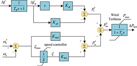
FIGURE 3. Inertial control structure.
The lower part of the controller is the speed controller, its mathematical model type is
where KWP and KWI are the control coefficients of the PI controller.
It can be seen from Figure 3 that the total active power output of the system fan under this control is
The additional controller based on differential links, as described above, can simulate the inertial response of wind turbines according to the system frequency change rate. When the grid frequency changes, it compensates the power shortage of the system and provides inertial support. However, the additional inertia control interacts with the speed controller in dynamic adjustment, making it difficult to achieve the desired control objectives.
The virtual inertia control strategy based on power tracking is optimized based on traditional maximum power tracking control, and alleviates the sudden change of grid frequency through the change of its own rotational speed and kinetic energy, so that the variable speed wind turbine has the ability to support the inertia of the system. The principle block diagram of this control strategy is shown in Figure 4. The active power and speed regulation are achieved by changing the scale factor kopt of the maximum power tracking curve.
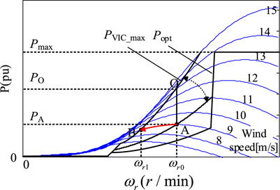
FIGURE 4. Schematic diagram of power tracking curve switching of virtual inertia.
This strategy finds the steady state by power tracking when the wind speed varies, it can improve the stability of the system in the process of speed regulation. When there is a sudden increase in power resulting in a sudden drop in frequency, the fan speed is reduced and released kinetic energy, and the operating state is switched from point A to point B in Figure 4, in this transient process, the power at points A and B is approximately equal, that is
where ωr0 and ωr1 are the rotational speeds corresponding to two points AB respectively.
Therefore, the scale factor of the new power tracking curve can be calculated by the following equation
According to Eq. 19, after introducing the frequency deviation signal, a new maximum power tracking scale factor can be obtained to adjust the speed variation. The amplitude range is limited by the scaling factor kopt, and Eq. 20 ensures a stable operating point in a wide range of wind speeds. The control takes full advantage of the rapid regulation capability of wind turbines and provides dynamic frequency support for the grid.
The traditional maximum power point tracking of wind turbines depends on the proportional coefficient of the power tracking curve kopt. Wang et al. (2015) provides a detailed analysis of the virtual inertia control based on power tracking, and this paper optimizes the power tracking curve in the virtual inertia control on this basis. The active reference is as follows
where kVIC is the proportional coefficient of the power tracking curve under virtual inertia control and the period value can be adjusted by the system frequency deviation value. kλ can be defined as the frequency adjustment coefficient.
The structure of the virtual inertial controller based on power tracking optimization is shown in Figure 5, where the power tracking curve can be recovered with frequency after the inertial response is completed. It can be seen from Eq. 21 that, the power tracking curve changes with the proportional coefficient kVIC. At the same time, by adjusting its value, the optimal power tracking curve can be found. Eq. 22 shows that the virtue inertia of the wind turbine, in addition to its own inherent inertia, depends on the angular velocity ωr0 of the wind turbine before the frequency change of the system and its frequency regulation factor kλ.
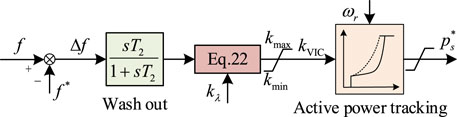
FIGURE 5. Virtual inertial control structure diagram.
In view of the above analysis, this paper proposes fuzzy logic control rules for online optimization of the frequency regulation coefficient to improve the inertia support capability of the system. The fuzzy logic controller consists of three parts: fuzzification, fuzzy inference, and defuzzification. The requirement is lower and the control is based on expert experience. As shown in Figure 6, the block diagram of virtual inertial control based on fuzzy logic control is constructed.
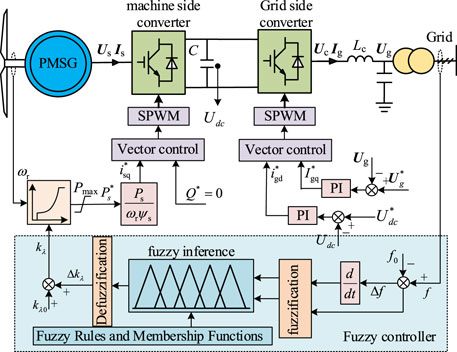
FIGURE 6. Block diagram of virtual inertial control based on fuzzy control.
The input and output of the fuzzy logic controller are exact quantities, and the fuzzy values are obtained after fuzzification. Then the fuzzy values are input to fuzzy inference for processing. Finally, the output quantities can be obtained by defuzzification. When using MATLAB toolbox to build a fuzzy logic controller, it is necessary to design the basic domain of input and output quantities and their corresponding fuzzy subsets, affiliation functions, and to specify the fuzzy rule table. In order to be able to adjust the frequency regulation coefficient more accurately and maximize the optimization effect, this paper takes the frequency deviation amount Δf = f−f0 and the frequency change rate dΔf/dt as fuzzy input variables and the output variable of the fuzzy controller is Δkλ. The fuzzy rules are used to adjust the frequency regulation coefficient kλ online. The fuzzy rule table of Δkλ is shown in Table.1. The table shows that when the system frequency is lower than the rated frequency of 50 Hz, the system frequency change rate is measured. If the change rate is negative, the frequency continues to decrease at this time, and the frequency regulation coefficient kλ needs to be reduced, and the proportional coefficient kVIC of the power tracking curve is increased by Eq. 22, thus increasing the active power from wind turbine and supporting the system frequency, and so on.

TABLE 1. Fuzzy rule table of Δkλ.
The fuzzy linguistic variable intervals are uniformly classified as (NB, NS, ZE, PS, PB) and have five interval subsets of NB (negative big), NS (negative small), ZE (zero), PS (positive small), and PB (positive big). The theoretical domain of the frequency deviation quantity Δf is (−0.6, −0.3, 0, 0.3, 0.6). The theoretical domain of the frequency change rate dΔf/dt is (−6, −3, 0, 3, 6), and the theoretical domain of Δkλ is (−0.4, −0.2, 0, 0.2, 0.4). The affiliation function is to map the input value in the fuzzy domain to an affiliation degree between 0 and 1. The function should be selected according to its selection principle. When the degree of intersection between the functions is large, the fuzzy controller has good robustness and low sensitivity, and when the degree of intersection is small, the sensitivity is high. Therefore, the intersection degree can be adjusted reasonably according to the variation law of input and output variables. In this paper, a combination of triangular and trapezoidal affiliation function is used for the fuzzy input variables, and a simple triangular affiliation function is used for the fuzzy output variables, and then the input and output affiliation functions are derived, as shown in Figure 7.
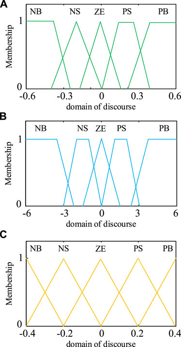
FIGURE 7. Membership function of each variable. (A) The affiliation function of the frequency deviation quantity Δf. (B) The affiliation function of the rate of change of frequency dΔf/dt. (C) The affiliation function of the output Δkλ.
In order to verify the effectiveness of the virtual inertial control method based on the fuzzy logic method proposed in this paper, a hardware-in-the-loop real-time simulation experiment is built based on the three-machine nine-node test system composed of wind turbines connected to the grid and two synchronous generators. The platform is shown in Figure 8. The experimental platform mainly consists of RT-LAB real-time simulator, RTU-BOX real-time digital controller and host computer, etc. Among them, the main topology of the three-machine nine-node test system model is mainly deployed in the RT-LAB real-time simulator, and the control strategies of other wind turbine controls including the grid-side converter and machine-side converter run in the RTU-BOX digital controller. The controller and the emulator are directly connected to the level conversion board through AD and DA interfaces. The experimental waveforms are recorded by a wave recorder.
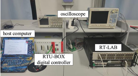
FIGURE 8. Hardware-in-the-loop real-time simulation experimental platform.
In the normal operation of the system, it is known that the total load of the system is 1800 MW, which is shared by the frequency modulation unit SG1, the constant power unit SG2, and the wind turbine. Among them, the frequency modulation unit SG1 is mainly used to provide support for the inertia and frequency of the system; the constant power unit SG2 emits a fixed active power of 400 MW, which is used to simulate the lack of inertia of the system and does not has the ability of frequency regulation. The wind turbine grid-connected system is used to verify the control strategy proposed in this paper. The rated frequency of the system is 50 Hz, and the system and control parameters can be seen in Table.2.
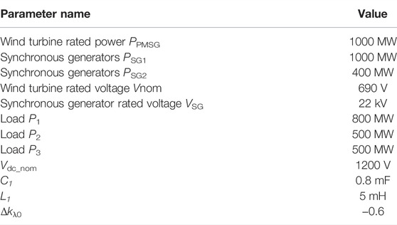
TABLE 2. System and control parameters.
In order to verify the virtual inertial control method based on fuzzy logic control proposed in this paper, in the 6th second of the normal operation of the system, a sudden increase of 500 MW load was carried out to test the dynamic response characteristics of this control strategy, and the experimental waveform was observed through a wave recorder.
Figure 9 shows the system frequency and output power waveforms under virtual-free inertia control and MPPT control. As can be seen from the figure, when the load is suddenly increased, the system frequency drops significantly, and the frequency drops to about 49.43 Hz, with a large fluctuation range and small oscillation amplitude. The power is mainly supported by the additional active power generated by the frequency-modulating unit, and the constant power unit SG2 issues constant active power.
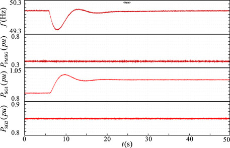
FIGURE 9. System frequency and output power under MPPT.
Figure 10 shows the system frequency and output power waveforms under the fixed inertia coefficient control. At this time, we can observe the frequency waveform, the system frequency also exists in the case of falling, but compared to the no virtual inertia control, the frequency drop range is significantly lower, only 49.72 Hz. The wind turbine will return to a constant output after the active power rises, which provides a certain support effect for the system frequency.

FIGURE 10. System frequency and output power under the fixed inertia coefficient control.
Figure 11 shows the system frequency and output power waveforms under the adaptive inertial control based on fuzzy logic control. It can be seen from the figure that when the load is suddenly increased, the lowest value of the system frequency is 49.85 Hz, with the smallest range of decline, and the wind turbine sends out a higher active rise and then resumes a constant output.
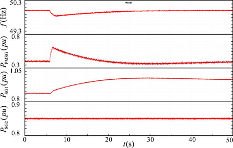
FIGURE 11. System frequency and output power under the adaptive inertial control based on fuzzy control.
Comparing the system frequency and output power waveforms under the three control methods, the system frequency decreases under the three different control methods when the system suddenly increases the load, and the corresponding lowest values of frequency are 49.43 Hz, 49.72 Hz, and 49.85 Hz, respectively. Compared with the virtual inertia-free control, the inertia control strategy with a fixed frequency adjustment coefficient can effectively reduce the deviation, and the frequency reduction amplitude is reduced by about 49%. However, compared with the adaptive inertial control based on fuzzy control proposed in this paper, the amplitude of frequency reduction is smaller, and the frequency deviation value is reduced by about 53% compared with the inertial control with a fixed frequency adjustment coefficient. It is obtained from the output power waveform that the adaptive inertia control wind turbine based on fuzzy logic control emits more active power to support the system after a sudden load increase. It can be seen that the method proposed in this paper can significantly improve the system frequency support capability and enhance the system stability. Figure 12 shows the frequency response waveforms of the system under different controls. It can be seen from the figure that in the case of sudden load increase, the frequency of adaptive adjustment of inertia coefficient based on fuzzy logic control proposed in this paper falls the least and reaches stability as soon as possible, which further verifies the effectiveness of the modified control.
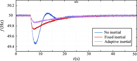
FIGURE 12. System frequency under different controls.
Due to the increased penetration of wind power in the AC grid, the inertia of the power system is missing, and the frequency problem of the system is affected. Aiming at this problem, this paper proposes a virtual inertial control based on fuzzy logic control. It is used for wind turbine participation in grid frequency support. Based on power tracking, the method uses fuzzy rules to optimize power tracking online, so as to improve system inertia and enhance system frequency support capability. Finally, a hardware-in-the-loop test platform is built based on the 3-machine 9-node test system to verify the effectiveness of the proposed method.
The raw data supporting the conclusions of this article will be made available by the authors, without undue reservation.
QUL, BR, QIL, DW, WT, and XW were responsible for the main writing of the paper. JM conceived the idea for this survey paper. All authors contributed to the article and approved the submitted version.
This work was supported by the Science and Technology Project of State Grid Jiangsu Electric Power Company Limited (J2021177) (Research on the influence mechanism of high aggregation access of offshore wind farms on the inertia of Jiangsu Power grid and key technologies to improve the accommodation capacity).
Authors QUL, BR, QIL, DW, and WT were employed by the company State Grid Jiangsu Electric Power Company Ltd. Research Institute. Author BR was employed by the company State Grid Jiangsu Electric Power Company Ltd.
The remaining authors declare that the research was conducted in the absence of any commercial or financial relationships that could be construed as a potential conflict of interest.
All claims expressed in this article are solely those of the authors and do not necessarily represent those of their affiliated organizations, or those of the publisher, the editors and the reviewers. Any product that may be evaluated in this article, or claim that may be made by its manufacturer, is not guaranteed or endorsed by the publisher.
Athari, M. H., and Ardehali, M. M. (2016). Operational Performance of Energy Storage as Function of Electricity Prices for On-Grid Hybrid Renewable Energy System by Optimized Fuzzy Logic Controller. Renew. Energy 85, 890–902. doi:10.1016/j.renene.2015.07.055
Bao, W., Wu, Q., Ding, L., Huang, S., and Terzija, V. (2021). A Hierarchical Inertial Control Scheme for Multiple Wind Farms with BESSs Based on ADMM. IEEE Trans. Sustain. Energy 12 (2), 751–760. doi:10.1109/TSTE.2020.2995101
Chau, T. K., Yu, S. S., Fernando, T. L., Iu, H. H., and Small, M. (2018). A Novel Control Strategy of DFIG Wind Turbines in Complex Power Systems for Enhancement of Primary Frequency Response and LFOD. IEEE Trans. Power Syst. 32 (5), 1811–1823. doi:10.1109/tpwrs.2017.2726160
Fang, J., Li, H., Tang, Y., and Blaabjerg, F. (2018). Distributed Power System Virtual Inertia Implemented by Grid-Connected Power Converters. IEEE Trans. Power Electron. 33 (10), 8488–8499. doi:10.1109/tpel.2017.2785218
Holdsworth, L., Ekanayake, J. B., and Jenkins, N. (2004). Power System Frequency Response from Fixed Speed and Doubly Fed Induction Generator-Based Wind Turbines. Wind Energy 7, 21–35. doi:10.1002/we.105
Karimi, A., Khayat, Y., Naderi, M., Dragicevic, T., Mirzaei, R., Blaabjerg, F., et al. (2020). Inertia Response Improvement in AC Microgrids: A Fuzzy-Based Virtual Synchronous Generator Control. IEEE Trans. Power Electron. 35 (4), 4321–4331. doi:10.1109/TPEL.2019.2937397
Kerdphol, T., Watanabe, M., Hongesombut, K., and Mitani, Y. (2019). Self-Adaptive Virtual Inertia Control-Based Fuzzy Logic to Improve Frequency Stability of Microgrid with High Renewable Penetration. IEEE Access 7, 76071–76083. doi:10.1109/access.2019.2920886
Kheshti, M., Ding, L., Bao, W., Yin, M., Wu, Q., and Terzija, V. (2020). Toward Intelligent Inertial Frequency Participation of Wind Farms for the Grid Frequency Control. IEEE Trans. Ind. Inf. 16 (11), 6772–6786. doi:10.1109/TII.2019.2924662
Lalor, G., Mullane, A., and O'Malley, M. (2005). Frequency Control and Wind Turbine Technologies. IEEE Trans. Power Syst. 20 (4), 1905–1913. doi:10.1109/TPWRS.2005.857393
Liu, B., Zhao, J., Huang, Q., Milano, F., Zhang, Y., and Hu, W. (2021). Nonlinear Virtual Inertia Control of WTGs for Enhancing Primary Frequency Response and Suppressing Drivetrain Torsional Oscillations. IEEE Trans. Power Syst. 36 (5), 4102–4113. doi:10.1109/TPWRS.2021.3055262
Long, B., Liao, Y., Chong, K. T., Rodriguez, J., and Guerrero, J. M. (2021). Enhancement of Frequency Regulation in AC Microgrid: A Fuzzy-MPC Controlled Virtual Synchronous Generator. IEEE Trans. Smart Grid 12 (4), 3138–3149. doi:10.1109/TSG.2021.3060780
Miao, L., Wen, J., Xie, H., Yue, C., and Lee, W.-J. (2015). Coordinated Control Strategy of Wind Turbine Generator and Energy Storage Equipment for Frequency Support. IEEE Trans. Ind. Appl. 51 (4), 2732–2742. doi:10.1109/TIA.2015.2394435
Nguyen, H. T., Yang, G., Nielsen, A. H., and Jensen, P. H. (2019). Combination of Synchronous Condenser and Synthetic Inertia for Frequency Stability Enhancement in Low-Inertia Systems. IEEE Trans. Sustain. Energy 10 (3), 997–1005. doi:10.1109/tste.2018.2856938
Oshnoei, A., Kheradmandi, M., Muyeen, S. M., and Hatziargyriou, N. D. (2021). Disturbance Observer and Tube-Based Model Predictive Controlled Electric Vehicles for Frequency Regulation of an Isolated Power Grid. IEEE Trans. Smart Grid 12 (5), 4351–4362. doi:10.1109/TSG.2021.3077519
Ren, M., Li, T., Shi, K., Xu, P., and Sun, Y. (2021). Coordinated Control Strategy of Virtual Synchronous Generator Based on Adaptive Moment of Inertia and Virtual Impedance. IEEE J. Emerg. Sel. Top. Circuits Syst. 11 (1), 99–110. doi:10.1109/JETCAS.2021.3051320
Tan, C., Li, Y., Lan, Q., Xiao, X., Ding, Q., Zhang, X., et al. (2020). Multi-Area Automatic Generation Control Scheme Considering Frequency Quality in Southwest China Grid: Challenges and Solutions. IEEE Access 8, 199813–199828. doi:10.1109/ACCESS.2020.3035067
Terazono, D., Liu, J., Miura, Y., Sakabe, S., Bevrani, H., and Ise, T. (2021). Grid Frequency Regulation Support from Back-To-Back Motor Drive System with Virtual-Synchronous-Generator-Based Coordinated Control. IEEE Trans. Power Electron. 36 (3), 2901–2913. doi:10.1109/TPEL.2020.3015806
Wang, S., and Tomsovic, K. (2018). A Novel Active Power Control Framework for Wind Turbine Generators to Improve Frequency Response. IEEE Trans. Power Syst. 33 (6), 6579–6589. doi:10.1109/TPWRS.2018.2829748
Wang, Y., Meng, J., Zhang, X., and Xu, L. (2015). Control of PMSG-Based Wind Turbines for System Inertial Response and Power Oscillation Damping. IEEE Trans. Sustain. Energy 6 (2), 565–574. doi:10.1109/tste.2015.2394363
Yan, W., Cheng, L., Yan, S., Gao, W., and Gao, D. W. (2020). Enabling and Evaluation of Inertial Control for PMSG-WTG Using Synchronverter with Multiple Virtual Rotating Masses in Microgrid. IEEE Trans. Sustain. Energy 11 (2), 1078–1088. doi:10.1109/TSTE.2019.2918744
Keywords: PMSG, wind turbines, virtual inertial control, fuzzy logic, frequency support
Citation: Li Q, Ren B, Li Q, Wang D, Tang W, Meng J and Wu X (2022) Virtual Inertial Control Strategy Based on Fuzzy Logic Algorithm for PMSG Wind Turbines to Enhance Frequency Stability. Front. Energy Res. 10:907770. doi: 10.3389/fenrg.2022.907770
Received: 30 March 2022; Accepted: 19 April 2022;
Published: 05 May 2022.
Edited by:
Kaiqi Sun, Shandong University, ChinaReviewed by:
Hengshan Xu, China Three Gorges University, ChinaCopyright © 2022 Li, Ren, Li, Wang, Tang, Meng and Wu. This is an open-access article distributed under the terms of the Creative Commons Attribution License (CC BY). The use, distribution or reproduction in other forums is permitted, provided the original author(s) and the copyright owner(s) are credited and that the original publication in this journal is cited, in accordance with accepted academic practice. No use, distribution or reproduction is permitted which does not comply with these terms.
*Correspondence: Jianhui Meng, bWVuZ2ppYW5odWkyMDA4QDE2My5jb20=
Disclaimer: All claims expressed in this article are solely those of the authors and do not necessarily represent those of their affiliated organizations, or those of the publisher, the editors and the reviewers. Any product that may be evaluated in this article or claim that may be made by its manufacturer is not guaranteed or endorsed by the publisher.
Research integrity at Frontiers
Learn more about the work of our research integrity team to safeguard the quality of each article we publish.