 Xiaoxu Ma
 Taicheng Liu1
 Shijie Li
95% of researchers rate our articles as excellent or good
Learn more about the work of our research integrity team to safeguard the quality of each article we publish.
Find out more
ORIGINAL RESEARCH article
Front. Energy Res. , 27 May 2022
Sec. Bioenergy and Biofuels
Volume 10 - 2022 | https://doi.org/10.3389/fenrg.2022.906809
This article is part of the Research Topic High-performance Catalytic Processes for Biofuel Production View all 6 articles
In this work, the perturbation length of vertical U-bend effects on the air–water two-phase flow in their adjacent straight tubes was investigated experimentally at ambient pressure and temperature. The experimental database covered test sections with three inner diameters of U-tubes (9, 12, and 16 mm), two curvature ratios (8.33 and 12.5), and two orientations (downward and upward). The air and water superficial velocities varied from 0.18 to 25.11 m/s and from 0.11 to 1.98 m/s, respectively. The dissipation of U-bend effects in the regions upstream and downstream of U-bends is characterized by the variation regularities of segmental pressure gradients along the contiguous straight tubes. It was found that the significant value of the dimensionless perturbation length (Lp/D) is less than 60 for the experimental conditions in this study. The influences of the inlet volume void fraction, two-phase mixed Froude number, mixed Weber number, and mixed Dean number on dimensionless perturbation length (Lp/D) are similar. With the increase in these parameters, Lp/D presents a unimodal distribution which first increases and then decreases. The maximum value of Lp/D takes place at a volume void fraction of around 90%. New dimensionless correlations to predict the influence length of U-bends on the straight tubes upstream and downstream have been provided. The prediction errors of 80% of data are within ± 30% compared with the present experimental data.
With the increasing depletion of fossil energy and the requirements of environmental protection, biomass and biofuel are widely used in many industrial fields recently. Accurate hydraulic design of the heat exchangers for the processes of biomass utilization and biofuel production plays a vital role in reducing the pump energy consumption. Return U-bends are primary elements of the heat exchangers such as evaporators and condensers due to the reason that they can redirect the flow and improve the compactness of devices. Unlike the flow in straight tubes, the two-phase flow in return U-bends is interacted by gravitational, centrifugal, viscous, and surface tension forces. These forces modify the distribution of gas–liquid interfaces and produce such phenomena as secondary flow, reversal, coalescence, and flooding (Usui et al., 1980, 1981). Consequently, global and local flow parameters in U-bends and their adjacent straight tubes are subject to significant influences compared to those in fully developed straight tubes. Therefore, it is very important and necessary to investigate the influence of U-bends on the hydrodynamic characteristics, and these “U-bend effects” should be considered in the design to gain more accurate and effective two-phase flow devices.
Experimental studies on the flow pattern observation (Jo et al., 2022; Liu et al., 2022; Pietrzak, 2014a, b; Pietrzak and Witczak, 2013; Sharma et al., 2011a), two-phase pressure drop (Domanski and Hermes, 2008; Padilla et al., 2009; Sharma et al., 2011b; de Oliveira and Barbosa, 2014; Dassler and Janoske, 2019), the gas fraction (Pietrzak and Witczak, 2013; Pietrzak, 2014a; de Oliveira and Barbosa, 2014), and liquid film thickness (Abdulkadir et al., 2014; Abdulkadir et al., 2018; López et al., 2020) across the U-bend itself have been conducted in recent years. The results showed that return U-bends cause secondary vortex and redistribution of the gas–liquid interface, which greatly affect the evolution of two-phase flow parameters. Most of these studies focus on the U-bend region itself. However, there are research studies (Traviss and Rohsenow, 1971; Wang et al., 2003; Wang et al., 2004; Wang et al., 2005; Wang et al., 2008; Dang et al., 2018; Qiao et al., 2018; Qiao and Kim, 2018; Jatau and Bello-Ochende, 2021) indicating that bend-effects also occur immediately upstream and downstream of bends. As a result, two-phase pressure gradients across the up- and downstream of the U-bend are different from those in the fully developed straight pipe section. However, equivalent pressure gradients immediately up- and downstream of bends (Chen et al., 2004; Domanski and Hermes, 2008; Padilla et al., 2009; Padilla et al., 2011; Padilla et al., 2013; Usui et al., 1980, 1981) were calculated from those of the distant fully developed pipe section, resulting in inaccurate prediction correlations of the frictional pressure drop. These show that a more accurate prediction of the two-phase pressure drop along the entire U-tube (both bend and its adjacent straight tube sections) is still challenging, and further investigation of the length and intensity of U-bend effects on the upstream and downstream is first in importance.
Several scholars (Traviss and Rohsenow, 1971; Hoang and Davis, 1984; Da Silva Lima and Thome, 2010, 2012; De Kerpel et al., 2012; Padilla et al., 2012; Padilla et al., 2013; de Oliveira et al., 2014; De Kerpel et al., 2016; Aliyu et al., 2017) have qualitatively and quantitatively investigated the length and intensity of U-bend effects at different flow and geometric conditions. Traviss and Rohsenow (1971) measured condensation pressure drops and heat transfer coefficients of R-12 along the straight tube with immediately vertical U-bends (D = 8 mm and 2R/D = 3.17 and 6.35). The results showed that the influence of the U-bend on downstream straight pipe pressure drop can be extended to 90D. Hoang and Davis (1984) experimentally studied the variation of flow patterns and static pressures for air–water bubble flow through inverted U-tubes (D = 25.4 mm and 2R/D = 4 and 6). It was found that the length of the region that is affected by the U-bend is about 9D. Da Silva Lima and Thome, 2010 indicated that the effect of horizontal U-bends on the downstream pressure gradient of R134a can be as far as 141D pipe diameter. Later, Da Silva Lima and Thome (2012) carried out flow visual observations of the refrigerant R-134a in horizontal and vertical U-tubes. The dissipation length downstream of U-bends was characterized based on the visual flow performances and was found to be longer in the upward flow for vertical U-bends. Padilla et al. (2012), Padilla et al. (2013) measured the pressure drop to identify the perturbation lengths upstream and downstream of the vertical and horizontal U-tubes for R134a, respectively. They found that the perturbation length upstream is usually less than 10D, while the perturbation length downstream is less than 20D. de Oliveira et al. (2014) carried out pressure drop and gas holdup measurements to study the influence of a U-bend on the flow characteristics. Their results showed that significant pressure gradient changes were confined to 40D upstream and 60D downstream of the bend. De Kerpel et al. (2016) investigated the affected length up- and downstream of a sharp U-bend (internal diameter of 8 mm and curvature radius of 11 mm) based on the void fraction and wavelet variance derived from the axial capacitance signal. They determined that the upstream affected length is less than 10D and that the downstream affected length is more than 30D. Aliyu et al. (2017) conducted an experimental investigation on the two-phase flow behavior in a vertical tube section downstream of a U-bend (D = 101.6 mm) with a serpentine configuration. They stated that the flow downstream of the U-bend stabilized when reaching 30 pipe diameters.
In general, these works investigated the length of the region influenced by U-bends based on the two-phase pressure drop or void fraction measurements along axial straight pipe sections. However, relevant investigation is still limited. In addition, due to the differences in fluid properties, flow conditions, and channel geometries, perturbation lengths determined by different researchers may differ significantly. Therefore, it is essential to study the impacts of dimensionless factors integrating flow parameters and geometric parameters. Additionally, no model is available for predicting the perturbation length of U-bends.
This work continues the efforts of studying the effect of vertical U-bends on the air–water two-phase flow in their contiguous straight tubes and developing predictive models of the vertical U-bend perturbation length. Specifically, the objectives of this study are as follows: 1) to extend the experimental database for U-bends’ perturbation length in different flow conditions and geometric parameters, 2) to determine the dimensionless influencing parameters of the perturbation length, and 3) to propose U-bends’ perturbation length correlations that predict the regions subjected to the effect of vertical U-bends.
The experiments have been conducted in an air–water two-phase experiment loop, as shown in Figure 1. The experimental system comprises an air flow path, a water flow path, a test section, and a data acquisition system. A detailed and complete discussion of the experimental apparatus, test flowmeters, and experimental system reliability can be found in Ma et al. (2018). It should be emphasized that the test section was improved to quantify the influence of a U-bend on the development of air–water flows in its contiguous horizontal straight tubes. The detailed arrangement for the test section is described as follows.
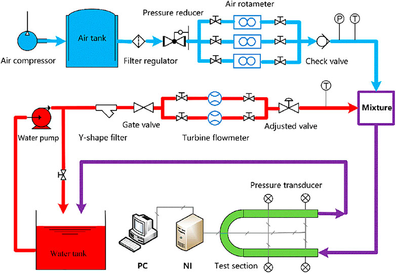
FIGURE 1. Schematic diagram of the experimental loop.
A gas–liquid adiabatic two-phase flow in a horizontal tube can be considered reaching a developed condition when the pressure gradient varies very little along the straight tube (Da Silva Lima and Thome, 2010; De Kerpel et al., 2012; de Oliveira et al., 2014; Traviss and Rohsenow, 1971). Therefore, in these studies, pressure drops were obtained as a function of the axial position to investigate how the flow disturbances in U-bends affect the flow behavior upstream and downstream of the bends.
Figure 2 shows details of the test section for pressure drop measurements. It was a U-tube including a U-bend (AB) and two straight tubes (IA and BO). The U-tube was made of transparent quartz glass. It was fixed horizontally. Both two straight tubes were in the same vertical plane. The physical picture of a test section is shown in Figure 3. As observed from P1-P8 and P1´-P8´ in Figure 2, eight pressure taps were located at axial 5D, 10D, 20D, 30D, 45D, 60D, 80D, and 130D upstream and downstream of the return bend, respectively. To have a fully developed flow condition, the inlet section (IP8) with 80D length was installed upstream of the P7P8.
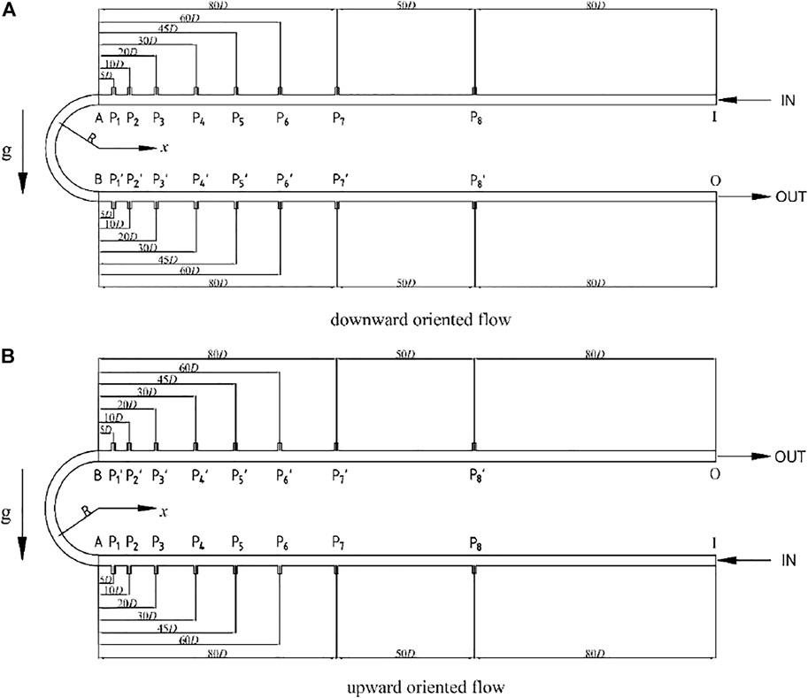
FIGURE 2. Test sections for pressure drop measurements. (A) Downward oriented flow and (B) upward oriented flow.
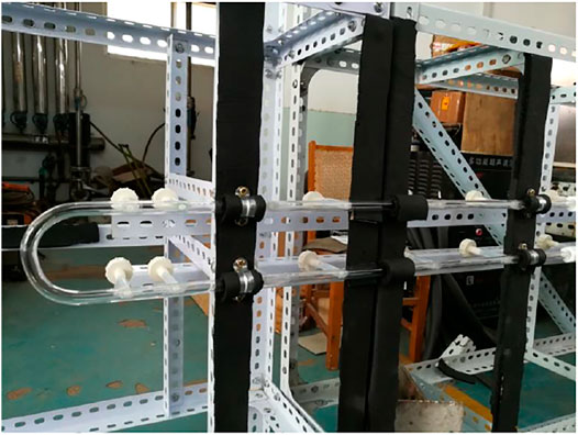
FIGURE 3. Physical picture of a test section.
As shown in Figure 2, the positive direction of the x-axial was directed to the right. The dimensionless distance was defined a negative value when the flow direction was opposite to the x-axis, and it was defined a positive value when the flow direction was consistent with the x-axis. In other words, the pressure taps in the inlet straight tube section were positioned at −5D, −10D, −20D, −30D, −45D, −60D, −80D, and −130D, whereas the pressure taps in the outlet straight tube section were positioned at +5D, +10D, +20D, +30D, +45D, +60D, +80D, and +130D. In this sense, the definition can exactly describe the axial pressure tap distribution along the entire U-tube.
The segmental pressure gradients (P8P7 to P2P1 and P1P2 to P7P8’) between the axial taps were obtained. It should be noted that the segmental pressure drop is the pressure difference between upstream and downstream along the segmented tube section. Based on the aforementioned definition of pressure tap distribution, the distance between the center of each segmented straight tube section to the bend inlet (A) or outlet (B) is shown in Table 1.
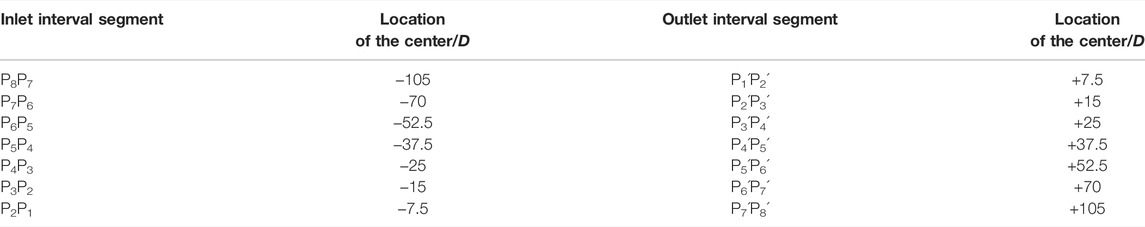
TABLE 1. Distance between the center of each segmental measurement section to the bend’s inlet (A) or outlet (B).
Experimental results of Da Silva Lima and Thome, 2010 stated that differences between the peripheral inner, outer, and top pressures up- and downstream of the bend are negligible, even very close to the bend. Therefore, the pressure tap in the current study was located at the outside of the cross section of the pipe (Figure 3). The diameter of a pressure tap was 1.0 mm. To obtain the effect of the diameter of pressure taps on measurements, a U-tube with D = 12 mm and R = 50 mm was manufactured. Compared to the test section in Figure 2, the pressure taps P1, P2, P4, P1’, P2, and P4 were removed in the U-tube. In Figure 4, the pressure data at P3 are compared under the existence or not of pressure taps (P1, P2, P4, P1’, P2, and P4’) under the same flow conditions. As observed, the pressure data with the aforementioned pressure taps agree favorably with that without the pressure taps. The relative deviation is only −1.2%. Therefore, the diameter of the 1.0-mm pressure tap is acceptable.
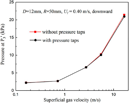
FIGURE 4. Effect of the 1-mm pressure tap on fluid pressure in the tube.
The pressure at each pressure tap was obtained by a diffused silicon pressure transducer with a repeatability of 0.05% and an accuracy of 0.2%. Pressure signals were recorded by using the data acquisition card PXIe-4492 of National Instruments under LabVIEW operating environments.
The working fluids were air and water with superficial velocities in ranges of 0.1–26 m/s and 0.2–2 m/s, respectively. All tests were carried out at a temperature of about 25°C and a pressure of about 0.1 MPa. Viscosity and density of gas are 1.84 × 10⁻⁵ kg/(m⋅s) and 1.18 kg/m3, respectively. Viscosity and density of liquid are 9.03 × 10⁻⁴ kg/(m⋅s) and 996.95 kg/m3, respectively. Experimental tests were conducted at downward and upward oriented flow. To study the effects of structure parameters on the perturbation length, three different U-tube geometries were selected and measured, as shown in Table 2. On the basis of the evaluation method of Moffat (1988), uncertainties of measurement parameters were estimated. The maximum fractional uncertainties on the superficial gas velocity, superficial liquid velocity, and pressure drop were 8.85%, 5.72%, and 3.06%, respectively.
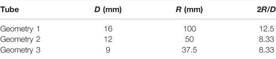
TABLE 2. Geometric parameters of the tested U-bends.
Dimensionless length (L/D) is defined as the ratio of the pipe length (L) to pipe diameter (D). Thus, the dimensionless length was discussed in the following sections of this study. The pressure gradient of the gas–liquid two-phase flow is closely related to the flow behavior characteristics (de Oliveira et al., 2014; De Kerpel et al., 2016). The pressure gradient change along the straight pipe upstream and downstream of the U-bends can reflect the perturbation degree of bends on the two-phase flow.
Figures 5, 6, respectively, show the upstream and downstream axial development of the segmental pressure gradient multiplier (Spg) for different two-phase flow conditions in a U-tube with D = 9 mm and R = 37.5 mm. Spg is the ratio of the axial segmental pressure gradient to the distal pressure gradient (−105D and +105D) for the upstream and downstream straight tubes of the U-bend.
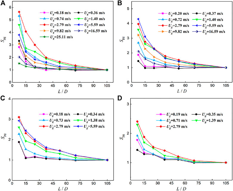
FIGURE 5. Axial development of Spg for the downstream straight tube of the U-bend (D = 9 mm and R = 37.5 mm) for the downward flow (A) Ul = 0.20 m/s; (B) Ul = 0.41 m/s; (C) Ul = 0.89 m/s; and (D) Ul = 1.98 m/s.
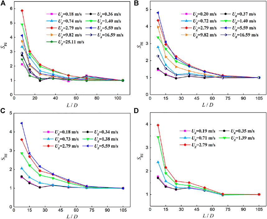
FIGURE 6. Axial development of Spg for the upstream straight tube of the U-bend (D = 9 mm and R = 37.5 mm) for the downward flow (A) Ul = 0.20 m/s; (B) Ul = 0.41 m/s; (C) Ul = 0.89 m/s; and (D) Ul = 1.98 m/s.
It is observed that Spg decreases with the increase in the distance from the U-bend at all working conditions, and the decreasing extent is getting smaller and smaller. These variation laws indicate that the perturbation degree of the U-bend on upstream and downstream straight tubes is smaller and smaller. However, the decreasing speed of the axial pressure gradient (the rate of Spg approaching 1) at different flow conditions is different. The faster the descent speed is, the shorter the interference length of the U-bend is. In general, it is acceptable to have a 30% relative error between the experimental pressure gradients at the inlet (−105D) and outlet (+105D) sections and the theoretical predictions. Therefore, the effect of U-bends on the two-phase flow in straight tubes is not obvious when the increment of the axial segmental pressure gradient is less than 30% compared with that of the fully developed section. In particular, the length segment (Lp) is considered as the perturbation length of the U-bend when Spg is greater than 1.3. Thus, the dimensionless perturbation length (Lp/D), defined as the ratio of perturbation length (Lp) to tube inner diameter (D), is an important parameter to characterize the effect of U-bends on the two-phase flow in their contiguous straight tubes.
As mentioned in the preceding section, dimensionless perturbation lengths have been identified by the change in axial pressure gradients in straight tubes. However, the specific perturbation length is affected by flow and geometry factors, such as the fluid superficial velocity, fluid physical property, tube diameter, and bend curvature radius. Two-phase flows in vertical U-bends interact with gravity, centrifugal, viscous, and surface tension forces that alter the phase interface distribution in the bend and vary the flow parameters up- and downstream of the bend. These variations disappear after a distance, referred to as the perturbation length, when U-bend effects weaken and vanish.
To study the combined role of flow conditions, geometry factors, and the aforementioned forces, the influence of dimensionless parameters (inlet volume void fraction β, two-phase Froude number Frm, Dean number Dnm, and Weber number Wem) on the perturbation length is analyzed in the following sections. Among these dimensionless factors, the inlet volume void fraction β impacts the phase interfacial mutual slip and affects the formation of the specific flow regimes. The Froude number is introduced to account for the influence of gravitational and centrifugal forces on the distribution and evolution of phase interfaces. This consideration was also presented by Usui et al. (1980), Pietrzak (2014a), and Padilla et al. (2013). In U-bends, the centrifugal force accelerates the fluid in the concave area of the curve tube while slowing the fluid in the convex parts. These result in a counter-rotating vortex pair of the secondary flow, known as Dean vortices. The Dean vortices strengthen with a decrease in the bend radius and increased fluid velocity and can be expressed by the dimensionless Dean number. When the tube diameter becomes smaller, surface tension plays a more significant role in the change of flow regime, which affect the perturbation length of U-bends. The influence is characterized by the Weber number, which is the ratio between inertia and surface tension.
Figure 7 shows the variation of the dimensionless perturbation length Lp/D with the inlet volume void fraction β.
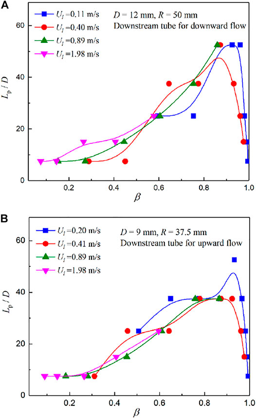
FIGURE 7. Effect of the inlet volume void fractionβ on the dimensionless perturbation length Lp/D. (A) Downstream tube for downward flow, D = 12 mm, R = 50 mm and (B) Downstream tube for upward flow, D = 9 mm, R = 37.5 mm.
It can be known from Figures 7A,B that Lp/D exhibits a right-skewed single-peak distribution with the increase in β. The change of Lp/D is very small when β is less than 40%, and it increases slowly to the maximum value when β is between 40% and 90%. Then, Lp/D decreased sharply with the increase in β. The aforementioned variations are intrinsically due to different flow patterns. The flow pattern in the U-bend is mainly the plug flow when β is less than 40%. Bubbles in the U-bend only change their trajectory due to the centrifugal force while their disturbance is not obvious, resulting in a small perturbation length. However, the flow pattern gradually changes to slug flow with an increase in β from 40% to 90%. The fluid direction of a fast-moving foamy liquid slug changes when it encounters the bend structure. Thus, the influence of the U-bend on slug flow in the contiguous straight tube is more significant under the action of gravity, interface shear force, and centrifugal force. With the increase of β (β > 90%), the flow pattern changes to annular flow. This flow pattern is relatively stable. A steady liquid film is present around the periphery of the U-bend. Many small liquid droplets are dispersed in the gas core. Therefore, the effect of U-bends on annular flow is negligible.
Figure 8 depicts the influence of the mixed Froude number Frm on the dimensionless perturbation length Lp/D. As can be seen in Figure 8, Lp/D shows a single-camel distribution which increases first and then decreases with the increase in Frm under low superficial liquid velocities. Under high superficial liquid velocities, Lp/D increases with increasing Frm. However, it can be inferred that Lp/D will also probably exhibit a single-camel distribution based on their variation trends when Frm continues to increase. The reasons are that the Froude number reflects the relative magnitude of inertial force and gravity. When the inertial force is small and gravity is relatively large, the Froude number will be small. For these working conditions, the fluid flow velocity is low, and most flow patterns are plug flow. Therefore, the perturbation of U-bends on the fluid in their contiguous tubes is not great. When the inertial force is great and gravity is small, the Froude number is large. For these conditions, the fluid flow velocity is high, and the flow pattern is mainly annular flow. For annular flow, the properties of the liquid film disturbance wave are regular and stable. Thus, the disturbance of the bend is also tiny. On the other hand, the Froude number is in the middle range when the inertial force and gravity act equally. The interaction of the two forces leads to unstable flow configurations, and the U-bend has a greater influence on the flow in its contiguous straight tubes.
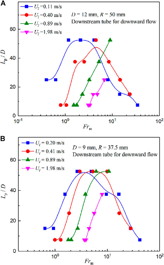
FIGURE 8. Effect of the mixed Froude number Frm on the dimensionless perturbation length Lp/D. (A) Downstream tube for downward flow, D = 12 mm, R = 50 mm and (B) Downstream tube for downward flow, D = 9 mm, R = 37.5 mm.
The effect of the dimensionless two-phase mixed Weber number Wem and Dean number Dnm on the dimensionless perturbation length Lp/D is similar to that of Frm, as shown in Figures 9, 10. They also showed a single-camel distribution, and the dimensionless number (Wem and Dnm) appearing in the camel increases with the increase in superficial liquid velocities. However, compared to the distribution under the influence of Frm, the camel distribution under the effect of Wem and Dnm is slightly broader and narrower, respectively. Moreover, the dimensionless perturbation length Lp/D increases sharply with the increase in Dnm on the left side of the camel in Figure 10, and the decreasing trend is gentler on the right of the camel, showing a left skewed distribution.
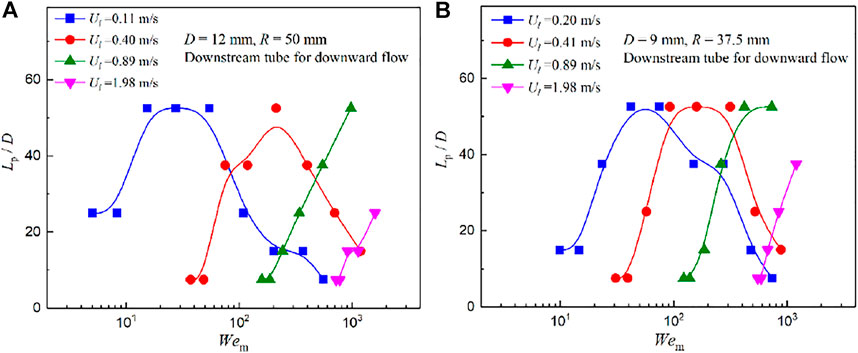
FIGURE 9. Effect of the mixed Weber number Wem on the dimensionless perturbation length Lp/D. (A) Downstream tube for downward flow D = 12 mm, R = 50 mm and (B) Downstream tube for downward flow D = 9 mm R = 37.5 mm.
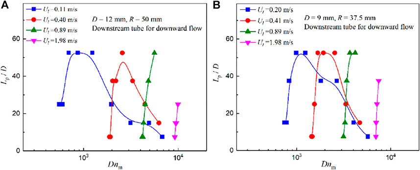
FIGURE 10. Effect of the mixed Dean number Dnm on the dimensionless perturbation length Lp/D. (A) Downstream tube for downward flow D = 12 mm, R = 50 mm and (B) Downstream tube for downward flow D = 9 mm, R = 37.5 mm.
Based on statements in section 3.2, there is a very large influence of dimensionless variables (inlet volume void fraction β, two-phase Froude number Frm, two-phase Weber number Wem, and two-phase Dean number Dnm) on the dimensionless perturbation length. Thus, the concrete form of a predictive model for the perturbation length of U-bends on two-phase flow characteristics in their contiguous straight tubes can be determined as follows:
where C is a constant number, and a, b, c, and d are exponential numbers.
The aforementioned constant number (C) and four exponents (a, b, c, d) are determined by fitting all experimental data. The results are presented in Table 3 for different flow orientations and straight tube sections. Figure 11 shows the comparison of the dimensionless perturbation length between the experimental data and values predicted by correlation Eq. 1 and Table 3.
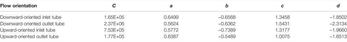
TABLE 3. Values of parameters C, a, b, c, and d in Eq. 1 for different flow orientations and straight tube sections.
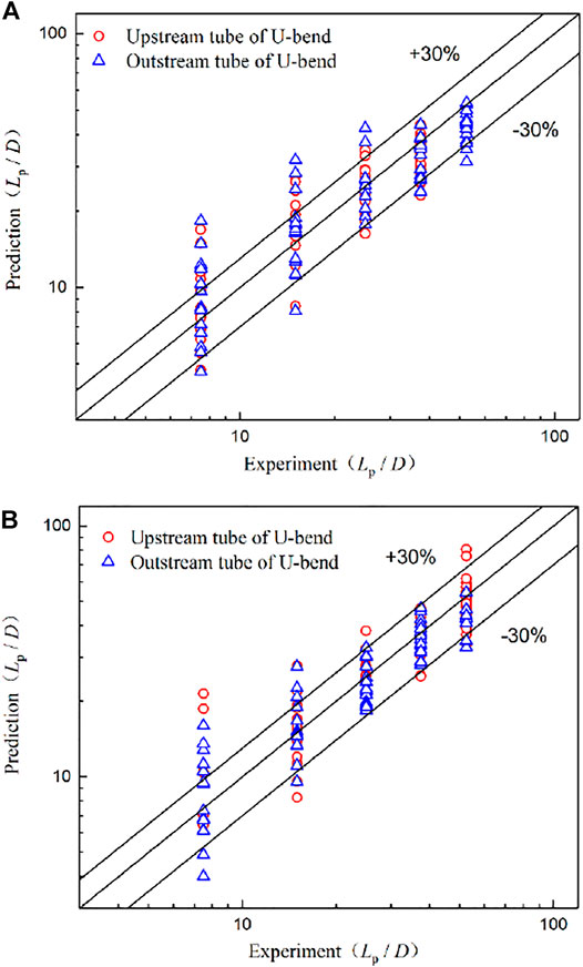
FIGURE 11. Comparisons of the dimensionless perturbation length between measurements and predictions. (A) Downward oriented flow and (B) upward oriented flow.
As can be observed in Figure 11, the significant value of Lp/D is less than 60 for the measurement conditions in the present study. Moreover, the proposed correlation predicts the experimental perturbation length with good agreement, with 80% of the data within a 30% error bound. Thus, Eq. 1 can be used to predict the effect of the U-bend on the air–water two-phase flow in its contiguous straight tubes. The scopes of application for the correlations are as follows: β = 0.07–1.0, Frm = 0.35–42, Wem = 5–1600, and Dnm = 550–10000. This model can also provide a new method to study the influence of other kinds of elbows on the two-phase flow in their adjacent tubes.
In this work, an experimental study has been conducted to obtain the affected lengths of the U-bend on the gas–liquid two-phase flow in their contiguous straight tubes. The fluid was air–water adiabatic two-phase flow with liquid and gas superficial velocities ranging from 0.11 to 1.98 m/s and from 0.18 to 25.11 m/s, respectively. Experimental measurements were performed at three different tube inner diameters (9, 12, and 16 mm), two curvature ratios (8.33 and 12.5), and two orientations (upward and downward). The evolution of the segmental pressure gradient along the adjacent straight tubes of vertical U-bends was used to identify the perturbation length of U-bends. In addition, influencing factors of the perturbation length were also analyzed. Major conclusions can be summarized as follows:
(1) Dimensionless perturbation length (Lp/D) was determined by the attenuation law of segmental pressure gradients along the axial direction of adjacent straight tubes. It was shown that the significant value of Lp/D is less than 60 for the test conditions in this study.
(2) Dimensionless perturbation length (Lp/D) exhibits a right-skewed single-peak distribution that first increases slowly and then decreases sharply with the increase in the inlet volume void fraction (β). The maximum value of Lp/D takes place at a volume void fraction of around 90%.
(3) The effects of the two-phase mixed Froude number Frm, Weber number Wem, and Dean number Dnm on Lp/D are similar to those of the inlet volume void fraction. As these dimensionless parameters increase, Lp/D presents a single hump distribution which first increases and then decreases.
(4) New correlations to predict the influence length of the U-bend on the straight tubes upstream and downstream have been proposed. The discrepancies of 80% of data between the predictive and experimental values are within ± 30%.
In the future, more flow conditions, channel geometric parameters, tube materials, and fluid properties will be studied, and flow visualization of inlet straight tube sections will be conducted to obtain predictive correlations of the perturbation length based on different flow patterns.
The original contributions presented in the study are included in the article/supplementary material; further inquiries can be directed to the corresponding authors.
XM put forward research ideas, carried out the experiments, and wrote the first draft of the manuscript. TL contributed to the data reduction and article revision. ND helped a lot during the experiments. MT contributed to the experimental design and supervised the whole process of the study. SL optimized the structure and tone of this manuscript. All authors contributed to the manuscript and approved the submitted version.
This work was supported by the National Natural Science Foundation of China (No. 52176080), the Shandong Provincial Natural Science Foundation of China (No. ZR2021ME045), and the Doctoral Fund of Shandong Jianzhu University (No. X19034Z).
The authors declare that the research was conducted in the absence of any commercial or financial relationships that could be construed as a potential conflict of interest.
All claims expressed in this article are solely those of the authors and do not necessarily represent those of their affiliated organizations, or those of the publisher, the editors, and the reviewers. Any product that may be evaluated in this article, or claim that may be made by its manufacturer, is not guaranteed or endorsed by the publisher.
D, tube internal diameter (mm); Dnm, two-phase mixed Dean number; Frm, two-phase mixed Froude number; L, tube length (mm); Lp/D, dimensionless perturbation length; R, bend radius (mm); Spg, segmental pressure gradient multiplier; Ug, superficial gas velocity (m/s); Ul , superficial liquid velocity (m/s); Wem, two-phase mixed Weber number; β, inlet volume void fraction.
Abdulkadir, M., Azzi, A., Zhao, D., Lowndes, I. S., and Azzopardi, B. J. (2014). Liquid Film Thickness Behaviour within a Large Diameter Vertical 180° Return Bend. Chem. Eng. Sci. 107, 137–148. doi:10.1016/j.ces.2013.12.009
Abdulkadir, M., Samson, J. N., Zhao, D., Okhiria, D. U., and Hernandez-Perez, V. (2018). Annular Liquid Film Thickness Prediction in a Vertical 180° Return Bend. Exp. Therm. Fluid Sci. 96, 205–215. doi:10.1016/j.expthermflusci.2018.03.006
Aliyu, A. M., Almabrok, A. A., Baba, Y. D., Lao, L., Yeung, H., and Kim, K. C. (2017). Upward Gas-Liquid Two-phase Flow after a U-Bend in a Large-Diameter Serpentine Pipe. Int. J. Heat Mass Transf. 108, 784–800. doi:10.1016/j.ijheatmasstransfer.2016.12.069
Chen, I. Y., Wang, C.-C., and Lin, S. Y. (2004). Measurements and Correlations of Frictional Single-phase and Two-phase Pressure Drops of R-410A Flow in Small U-type Return Bends. Int. J. Heat Mass Transf. 47, 2241–2249. doi:10.1016/j.ijheatmasstransfer.2003.11.016
Da Silva Lima, R. J., and Thome, J. R. (2012). Two-phase Flow Patterns in U-Bends and Their Contiguous Straight Tubes for Different Orientations, Tube and Bend Diameters. Int. J. Refrig. 35, 1439–1454. doi:10.1016/j.ijrefrig.2012.02.002
Dang, Z., Yang, Z., Yang, X., and Ishii, M. (2018). Experimental Study of Vertical and Horizontal Two-phase Pipe Flow through Double 90 Degree Elbows. Int. J. Heat Mass Transf. 120, 861–869. doi:10.1016/j.ijheatmasstransfer.2017.11.089
Dassler, C., and Janoske, U. (2019). Experimental Investigation of Single- and Two-phase Pressure Drop in Slender Rectangular 180° Return Bends. Exp. Therm. Fluid Sci. 103, 126–132. doi:10.1016/j.expthermflusci.2019.01.001
De Kerpel, K., Ameel, B., Huisseune, H., Tjoen, C., Canire, H., and De Paepe, M. (2012). Two-phase Flow Behaviour and Pressure Drop of R134a in a Smooth Hairpin. Int. J. Heat Mass Transf. 55, 1179–1188. doi:10.1016/j.ijheatmasstransfer.2011.09.052
De Kerpel, K., De Schampheleire, S., De Keulenaer, T., and De Paepe, M. (2016). Two-phase Frictional Pressure Drop and Flow Behaviour up- and Downstream of a Sharp Return Bend. Appl. Therm. Eng. 93, 824–838. doi:10.1016/j.applthermaleng.2015.10.064
de Oliveira, P. M., and Barbosa, J. R. (2014). Pressure Drop and Gas Holdup in Air-Water Flow in 180° Return Bends. Int. J. Multiph. Flow 61, 83–93. doi:10.1016/j.ijmultiphaseflow.2014.01.005
de Oliveira, P. M., Strle, E., and Barbosa, J. R. (2014). Developing Air-Water Flow Downstream of a Vertical 180° Return Bend. Int. J. Multiph. Flow 67, 32–41. doi:10.1016/j.ijmultiphaseflow.2014.05.006
Domanski, P. A., and Hermes, C. J. L. (2008). An Improved Correlation for Two-phase Pressure Drop of R-22 and R-410A in 180° Return Bends. Appl. Therm. Eng. 28, 793–800. doi:10.1016/j.applthermaleng.2007.06.034
Hoang, K., and Davis, M. R. (1984). Flow Structure and Pressure Loss for Two Phase Flow in Return Bends. J. Fluid Eng. 106, 30–37. doi:10.1115/1.3242398
Jatau, T., and Bello-Ochende, T. (2021). Heat Transfer and Flow Pattern Map Development of R134A in a U-Bend Tube for Flow Boiling Evaporation. Int. Commun. Heat Mass Transf. 128, 105629. doi:10.1016/j.icheatmasstransfer.2021.105629
Jo, Y., Song, Y. J., and Jo, D. (2022). Gas Accumulation Induced by Temperature Rise and Sudden Pressure Drop in an Inverse U-Bend. Ann. Nucl. Energy 169, 108928. doi:10.1016/j.anucene.2021.108928
Lima, R. J. d. S., and Thome, J. (2010). Two-Phase Pressure Drops in Adiabatic Horizontal Circular Smooth U-Bends and Contiguous Straight Pipes (RP-1444). HVAC&R Res. 16, 383–397. doi:10.1080/10789669.2010.10390910
Liu, W., Jiang, S., and Li, H. (2022). Experimental Study of Liquid-Carrying by Swirling Flow in a U-Shaped Tube. Exp. Therm. Fluid Sci. 130, 110479. doi:10.1016/j.expthermflusci.2021.110479
López, J., Ratkovich, N., and Pereyra, E. (2020). Analysis of Two-phase Air-Water Annular Flow in U-Bends. Heliyon 6 (12), e05818. doi:10.1016/j.heliyon.2020.e05818
Ma, X., Tian, M., Zhang, J., Tang, L., and Liu, F. (2018). Flow Pattern Identification for Two-phase Flow in a U-Bend and its Contiguous Straight Tubes. Exp. Therm. Fluid Sci. 93, 218–234. doi:10.1016/j.expthermflusci.2017.12.024
Moffat, R. J. (1988). Describing the Uncertainties in Experimental Results. Exp. Therm. Fluid Sci. 1, 3–17. doi:10.1016/0894-1777(88)90043-x
Padilla, M., Revellin, R., and Bonjour, J. (2009). Prediction and Simulation of Two-phase Pressure Drop in Return Bends. Int. J. Refrig. 32, 1776–1783. doi:10.1016/j.ijrefrig.2009.06.006
Padilla, M., Revellin, R., and Bonjour, J. (2012). Two-phase Flow Visualization and Pressure Drop Measurements of HFO-1234yf and R-134a Refrigerants in Horizontal Return Bends. Exp. Therm. Fluid Sci. 39, 98–111. doi:10.1016/j.expthermflusci.2012.01.013
Padilla, M., Revellin, R., Haberschill, P., and Bonjour, J. (2011). Two-phase Pressure Drop in Return Bends: Experimental Results for R-410A. Int. J. Refrig. 34, 1854–1865. doi:10.1016/j.ijrefrig.2011.03.009
Padilla, M., Revellin, R., Wallet, J., and Bonjour, J. (2013). Flow Regime Visualization and Pressure Drops of HFO-1234yf, R-134a and R-410A during Downward Two-phase Flow in Vertical Return Bends. Int. J. Heat Fluid Flow 40, 116–134. doi:10.1016/j.ijheatfluidflow.2013.01.005
Pietrzak, M. (2014a). Flow Patterns and Gas Fractions of Air-Oil and Air-Water Flow in Pipe Bends. Chem. Eng. Res. Des. 92, 1647–1658. doi:10.1016/j.cherd.2013.12.008
Pietrzak, M. (2014b). Flow Patterns and Volume Fractions of Phases during Liquid-Liquid Two-phase Flow in Pipe Bends. Exp. Therm. Fluid Sci. 54, 247–258. doi:10.1016/j.expthermflusci.2013.12.024
Pietrzak, M., and Witczak, S. (2013). Flow Patterns and Void Fractions of Phases during Gas-Liquid Two-phase and Gas-Liquid-Liquid Three-phase Flow in U-Bends. Int. J. Heat Fluid Flow 44, 700–710. doi:10.1016/j.ijheatmasstransfer.2018.04.02310.1016/j.ijheatfluidflow.2013.09.007
Qiao, S., and Kim, S. (2018). Air-water Two-phase Bubbly Flow across 90° Vertical Elbows. Part I: Experiment. Int. J. Heat Mass Transf. 123, 1221–1237. doi:10.1016/j.ijheatmasstransfer.2018.04.023
Qiao, S., Kong, R., and Kim, S. (2018). Air-water Two-phase Bubbly Flow across 90° Vertical Elbows Part II. Model. Int. J. Heat. Mass Transf. 123, 1238–1252. doi:10.1016/j.ijheatmasstransfer.2018.04.025
Sharma, M., Ravi, P., Ghosh, S., Das, G., and Das, P. K. (2011a). Hydrodynamics of Lube Oil-Water Flow through 180° Return Bends. Chem. Eng. Sci. 66, 4468–4476. doi:10.1016/j.ces.2011.04.031
Sharma, M., Ravi, P., Ghosh, S., Das, G., and Das, P. K. (2011b). Studies on Low Viscous Oil-Water Flow through Return Bends. Exp. Therm. Fluid Sci. 35, 455–469. doi:10.1016/j.expthermflusci.2010.11.007
Traviss, D. P., and Rohsenow, W. M. (1971). The Influence of Return Bends on the Downstream Pressure Drop and Condensation Heat Transfer in Tubes Tech. Rep., Heat Transfer Laboratory. Cambridge, Massachusetts: Department of Mechanical Engineering, MIT.
Usui, K., Aoki, S., and Inoue, A. (1980). Flow Behavior and Pressure Drop of Two-phase Flow through C-Shaped Bend in Vertical Plane, (I). J. Nucl. Sci. Technol. 17, 875–887. doi:10.1080/18811248.1980.9732670
Usui, K., Aoki, S., and Inoue, A. (1981). Flow Behavior and Pressure Drop of Two-phase Flow through C-Shaped Bend in Vertical Plane, (II). J. Nucl. Sci. Technol. 18, 179–190. doi:10.1080/18811248.1981.9733241
Wang, C.-C., Chen, I. Y., and Huang, P.-S. (2005). Two-phase Slug Flow across Small Diameter Tubes with the Presence of Vertical Return Bend. Int. J. Heat Mass Transf. 48, 2342–2346. doi:10.1016/j.ijheatmasstransfer.2004.12.036
Wang, C.-C., Chen, I. Y., Lin, Y.-T., and Chang, Y.-J. (2008). A Visual Observation of the Air-Water Two-phase Flow in Small Diameter Tubes Subject to the Influence of Vertical Return Bends. Chem. Eng. Res. Des. 86, 1223–1235. doi:10.1016/j.cherd.2008.06.008
Wang, C.-C., Chen, I. Y., Yang, Y.-W., and Chang, Y.-J. (2003). Two-phase Flow Pattern in Small Diameter Tubes with the Presence of Horizontal Return Bend. Int. J. Heat Mass Transf. 46, 2975–2981. doi:10.1016/s0017-9310(03)00071-1
Keywords: two-phase flow, air–water flow, U-bend, perturbation length, pressure gradient
Citation: Ma X, Liu T, Dai N, Tian M and Li S (2022) Experimental Investigation on the Perturbation Length for Air–Water Flow Upstream and Downstream of U-Bends. Front. Energy Res. 10:906809. doi: 10.3389/fenrg.2022.906809
Received: 29 March 2022; Accepted: 22 April 2022;
Published: 27 May 2022.
Edited by:
Feiqiang Guo, China University of Mining and Technology, ChinaReviewed by:
Weihua Cai, Northeast Electric Power University, ChinaCopyright © 2022 Ma, Liu, Dai, Tian and Li. This is an open-access article distributed under the terms of the Creative Commons Attribution License (CC BY). The use, distribution or reproduction in other forums is permitted, provided the original author(s) and the copyright owner(s) are credited and that the original publication in this journal is cited, in accordance with accepted academic practice. No use, distribution or reproduction is permitted which does not comply with these terms.
*Correspondence: Xiaoxu Ma, eGlhb3h1bWFoZ0AxNjMuY29t; Maocheng Tian, dGlhbm1jNjVAc2R1LmVkdS5jbg==
Disclaimer: All claims expressed in this article are solely those of the authors and do not necessarily represent those of their affiliated organizations, or those of the publisher, the editors and the reviewers. Any product that may be evaluated in this article or claim that may be made by its manufacturer is not guaranteed or endorsed by the publisher.
Research integrity at Frontiers
Learn more about the work of our research integrity team to safeguard the quality of each article we publish.