 Houchang Pei
 Chenguang Xiao
 Lu Xing
 Zhengkai Tu
- 1School of Mechanical Engineering, Wuhan Polytechnic University, Wuhan, China
- 2Mechanical and Construction Engineering, Northumbria University, Newcastle upon Tyne, United Kingdom
- 3School of Energy and Power Engineering, Huazhong University of Science and Technology, Wuhan, China
The proton exchange membrane fuel cell (PEMFC) demonstrates high commercial competitiveness due to its advantages: low operating temperature, high power/mass ratio, fast response, no emission, and low noise. Thermal and water management remains a challenging issue for ensuring the fuel cell’s performance at steady-state and dynamic conditions. The cathode moisture condensation uses a semiconductor cooler to effectively remove excess water from the PEMFCs and reduce the probability of flooding of the stack. The stack’s voltage uniformity is an essential factor that affects the performance and lifetime of PEMFC. This paper investigates the dynamic response characteristics of the voltage uniformity of a PEMFC stack under cathode moisture condensation conditions. The results show that the condensation temperature at 10°C during the steady-state or transient operation of the PEMFC can effectively optimize the stack’s performance. Compared to conventional PEMFC, applying the cathode moisture condensation technology to the PEMFC stack increases the stack voltage by 6% and decreases the voltage uniformity by up to 30%. This self-water-removal technology effectively improves the voltage uniformity of the stack, which then increase the stack durability.
1 Introduction
The proton exchange membrane fuel cell (PEMFC) demonstrates high commercial competitiveness due to its advantages such as low operating temperature, small size, fast start-up, and non-polluting (Stephen et al., 2019; Baldi et al., 2019). The main by-product is water in liquid form due to water vapor’s condensation in the stack at the low temperature (below 100°C) operation. A reasonable amount of liquid water ensures good wettability and performance of the membrane electrode assembly (MEA), the core component of the fuel cell stack. PEMFC’s steady-state and transient performance is highly impacted by its water management (Liu et al., 2020; Moçotéguy et al., 2020; Li et al., 2021; Zhang et al., 2021).
The lack of water results in a dehydrated membrane; this decreases the proton conductivity and significantly increases cell resistance. Wang et al. (2019) investigated the effects of hydrogen relative humidity, air relative humidity, operating temperature, and air stoichiometry ratio on the performance of PEMFC. The results showed that air relative humidity significantly impacts the PEMFC performance; the effect of hydrogen relative humidity on PEMFC performance was minimal. Wilberforce et al. (2019) investigated the effect of anode humidification on PEMFC on the performance. The results showed that fuel gas humidification significantly improved cell performance. The stack performance was better under all humidification conditions than under non-humidification conditions. Ozen et al. (2016) investigated the effects of inlet gas humidification level, inlet temperature, operating temperature, and oxidant type on the performance of the reactor. The results show that gas humidification has a positive effect on reactor performance. In contrast, higher operating temperature and inlet gas temperature will significantly improve the reactor performance. Cha et al. (2019) investigated the start-up characteristics of self-humidifying PEMFC under different temperature and voltage conditions. The results showed that the anode side humidifying has a more significant enhancement of the stack performance than the cathode side.
Asghari et al. (2016) used EIS to study the effects of operating temperature, air stoichiometry ratio, and purge interval on the performance of self-humidified dead ended PEMFC. The results showed that the cell performance was significantly improved when the stack temperature was increased by 50°C but continuing to increase the stack temperature would deteriorate performance; the accumulation of N2 at the anode would lead to an increase in mass transfer impedance. Yang et al. (2019) developed a transient PEMFC system model including the subsystems of the reactor, humidifier, air compressor, and heater to investigate the effect of different operating conditions on the performance of the reactor. Pérez-Page and Pérez-Herranz (2009) investigated the effect of humidification temperature on the performance of PEMFC. The results showed that under non-humidified conditions, the battery performance improved with increasing temperature from 20 to 40°C temperature. And when the stack temperature exceeds 40°C, the battery performance decreases due to MEA drying. A higher humidification temperature should be selected when using a higher stack temperature.
Excessive accumulation of liquid water in the channels can cause “flooding” which affects reaction gas supply and performance degradation. Due to water saturation, the carrier carbon on the catalytic layer participates in the reaction, causing electrochemical corrosion of the MEA’s catalytic layer shortens the fuel cell’s lifespan. Yang et al. (2017) studied the mechanism of voltage peak generation in a full dead-end PEMFC by dynamic voltage and local current measurements. The experimental results show that a local current density peak is also generated when the average current density is kept constant, and this peak is generated simultaneously as the voltage peak. It is also found that the local current density peak and the voltage peak are generated due to the backflow of liquid water and nitrogen in the anode channel.
Extra water must be drained from the stack to ensure that the MEA is at optimal humidity; water management is critical for the fuel cell’s performance at steady-state and dynamic conditions. Santarelli and Torchio (2007) investigated the effect of different operating conditions on the performance of a single cell. The results showed that higher cell temperature enhances the PEMFC performance. Under high current density conditions, the inlet gas humidification should be reduced to prevent flooding in the channel. Wan et al. (2013) investigate operating characteristics in a dead ended PEMFC when the self-water removal is applied to resolve the flooding issue and optimize the stack’s humidity condition and performance. The results show that the cell performance decreases with increasing condensation temperature, and the recovered liquid water is consistent with the theoretical value. Wan et al. (2012) used a condenser to separate liquid water from the outlet gas to achieve self-humidification of liquid water in an electric reactor and investigated the performance of the reactor. The results show that the choice of condenser temperature is not affected by the reactor’s operating temperature. The condenser outlet gas temperature can be used as a condenser temperature indicator to meet the humidification demand of the reactor when the condenser outlet temperature is lower than the theoretical value. Xia et al. (2019) investigated the effects of cathode inlet relative humidity, anode and cathode gas pressure, and anode stoichiometry ratio on the PEMFC’s performance. The results showed that the cell performance gradually weakened as the cathode gas humidity increased; increasing the anode gas pressure could retard the weakened cell performance caused by nitrogen spanning.
The PEMFC dynamic performance has also been investigated during the start-up or at various conditions. Lin et al. (2017) investigated the cold start phenomenon of three different flow field plates using segmented PEMFC. It was shown that the flow field structure has a significant effect on the cold start of the battery, and the single-channel serpentine flow field has the best cold start performance. And the results show that the cell temperature reaching 0°C does not mean the cold start is successful, as the temperature may fall back. Meanwhile, they further studied (Lin et al., 2014). They found that PEMFC has a strong cold start capability at −3°C to −5°C, and the polarization curve does not degrade significantly after starting while starting PEMFC at −10°C will lead to significant degradation of the polarization curve. And the study also showed that the high current density region was in the inlet region at the initial start-up and then moved rapidly to the middle. Jang et al. (2015) conducted dynamic response experiments using a homemade kW-level anode dead-end PEMFC. They showed that different purge intervals had essentially no effect on PEMFC performance at 30 A load conditions, but smaller purge intervals resulted in more minor voltage fluctuations. And the cell performance is reduced by 4% under the anode dead-end operation condition.
Previous research demonstrated the necessity and feasibility of self-water removal in a PEMFC to avoid flooding and performance degradation. A cathode moisture condensation technology can enhance the water vapor’s condensation at the dead-ended PEMFC stack outlet rather than in the active area such as MEA. When a semiconductor cooler is added at the stack cathode outlet, this significantly reduces the possibility of liquid water blocking the flow channel and covering the MEA, thus, improving the stack output performance (Pei et al., 2021). However, the effect of cathode moisture condensation on the durability of the stack is unclear. The voltage uniformity is an essential criterion for evaluating the fuel cell stack’s durability at steady-state and dynamic conditions. A fuel cell stack is composed of hundreds of single cells, failure of anyone is fatal for the whole stack. Thus, voltage uniformity is a critical index to judge the cell consistency and estimate the stack’s durability. Hu et al. (2019) proposed using the multipoint voltage monitoring method to study the homogeneity of PEMFC stacks and established a one-dimensional model to analyze the experimental phenomena. The results show that the multipoint voltage measurement method effectively avoids “voltage cheat.” Tang et al. (2013) investigated the effect of operating temperature on current density distribution and film resistance using the PCB technique. They showed that the current density distribution of MEA was most uniform at operating stability of 70°C, and this uniformity was destroyed with increasing load.
In 2017, DOE (Department of Energy, United States) reports on PEMFC stack testing criteria, including polarization curve test, cycle test, start/stop durability test et al. But little attention was paid on dead-ended proton exchange membrane fuel cell stack test. This paper conducted experimental research to demonstrate voltage behavior improvement of dead-ended proton exchange membrane fuel cell stack using the cathode moisture condensation technology. A semiconductor cooler condenser is added at the stack cathode outlet for self-water-removal. The experimental study on the PEMFC’s voltage uniformity at both steady-state and transient conditions was performed to investigate the fuel cell’s performance and durability when the cathode outlet gas is condensed. The research result can provide references and suggestions for the optimal design and efficient operation of PEMFC.
2 Experimental Methodology
2.1 Voltage Uniformity
The study of single-cell voltage uniformity is the study of the relative standard deviation of single-cell voltage, the ratio of the standard deviation of single-cell voltage to the mean value of single-cell voltage, which can be expressed as (Chen et al., 2021):
In this equation, N is the number of single cells, (j = 1, 2, ..., N), and
2.2 Proton Exchange Membrane Fuel Cell Stack Test System
The schematic and photos of the experimental platform are shown in Figure 1 and Figure 2. Figure 1 shows a dead-ended PEMFC test system diagram. Figure 2shows the dead-ended PEMFC stack and test platform. In the study, the MEAs with an active area of 100 cm2 are composed of 25-μm membranes combined with platinum loading of 0.4 mg cm−2 for anode and cathode in the experiment. Toray carbon paper, wet-proofed with fluorinated ethylene propylene resin, was employed as a gas diffusion layer (GDL). Nafion XL proton exchange membranes with borders were used for the experiments, and their specific parameters are shown in Table 1. The PEMFC with graphite bipolar plates, graphite bipolar plates are used as anode and cathode. In this study, the bipolar plate was made of commercially available graphite. The flow channels (each of which is 2-mm wide and 2-mm deep) that are evenly separated by 2-mm-wide bands for current collection. The fuel supply and electric current are both conveyed by the thin gold plate. The PEMFC stack is fixed by 8 screws, as shown in Figure 2C. The geometrical properties of the PEMFC single fuel cell are listed in Table 1. Figure 2B shows the flow field plate with thermocouple wires installed. T-type thermocouple wires were used for the temperature tests in the study, and nine thermocouple wires were sequentially arranged and numbered between the GDL and the flow field plate. Figure 2C shows an inner condensing unit which composed of condensing fins, semiconductor cooling sheets and radiator component pressed together in sequence were set near the cathode outlet. The radiator component was cooled by cooling water circulation. In addition, several T-Type thermocouples are used to monitor the condensing fin temperature during the experiments, and the accuracy of each thermocouple is approximately 0.1°C. The test system uses ITECH’s IT8514C + electronic load; the maximum current can reach 240 A, the test accuracy is ± 0.025% + 0.025%FS. The data acquisition uses KEITHLEY’s 40-channel automatic data acquisition instrument.
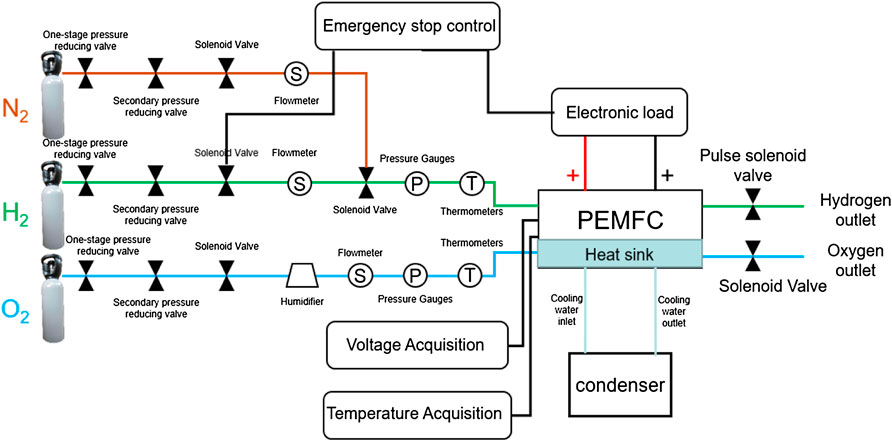
FIGURE 1. Diagram of full dead-ended proton exchange membrane fuel cell test system.
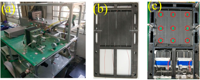
FIGURE 2. (A) Full dead-ended proton exchange membrane fuel cell testbed, (B) Single cell thermocouple distribution, (C) Stack with inner condensing units.
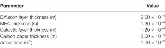
TABLE 1. MEA parameters.
The initial operating conditions of the experiment are: 60°C cell temperature, 50 A loading current, 50kPa gas inlet pressure fully closed port operation for 30min. After that, the cell operating temperature, loading current, and start-stop stack were varied. The same full dead-end operation was performed for 30 min to compare dead ended PEMFC performance changes under different operating parameters.
On this basis, the dead ended PEMFC drainage technology is optimized to condense the cathode outlet gas of the stack. The performance of the optimized cell is tested and compared with the performance of the dead ended PEMFC before optimization under the same operating conditions to analyze whether the phase change drainage technology has a catalytic effect on the improvement of stack performance.
3 Result and Discussion
3.1 Cathode Moisture Condensation’s Effect on Voltage
3.1.1 Effect on the Stack and Cell Voltage
Figure 3A shows the comparison of conventional PEMFC stack (without cathode moisture condensation)’s stack voltage with PEMFC stack (with cathode moisture condensation)’s stack voltage. The cathode moisture is condensed at the temperature of 5°C at a pressure of 50 kPa and different stack temperatures (50, 60, 70°C). The PEMFC stack demonstrates a voltage performance improvement at various current densities with cathode moisture condensation technology. At 200 mA cm−2 and at stack operating temperature 70°C, the PEMFC stack (with condensation)’s stack voltage is 10.0 V, the PEMFC stack (without condensation)’s stack voltage is 9.6 V. At 500 mA cm−2 and stack operating temperature 70°C, the PEMFC stack (with condensation)’s stack voltage is 9.0V, the PEMFC stack (without condensation)’s stack voltage is 8.5 V. The application of the cathode moisture condensation technology to the PEMFC stack increases the voltage by 6%.
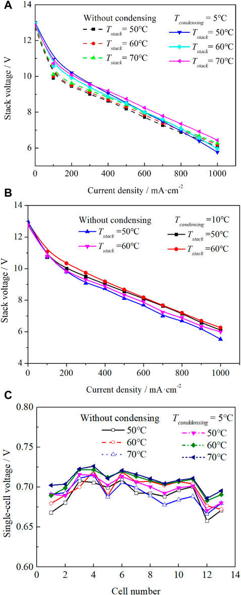
FIGURE 3. Performance comparison. (A) and (B) Stack voltage at different condensing temperature and without condensing, (C) Voltage distribution.
The differences between normal state and 10°C condensate was investigated. The stack voltage was significantly improved over a wide range of current density by using cathode moisture condensation at a condensing temperature of 10°C. As shown in Figure 3B, the output voltage of the stack was increased from 8.324 to 8.676 V with a growth rate of 4.23% at 500 mA cm−2. It attributes to the cathode moisture condensation, the vapor inside the stack was more easily transported to the outlet, and condensed into liquid water.
Figure 3C shows the single-cell voltage distributions of the PEMFC stack (without condensation) and PEMFC stack (with cathode moisture condensation). The outlet moisture is condensed at 5°C under a current density of 500 mA cm−2 and a pressure of 50 kPa. With cathode outlet gas condensation applied to the dead ended PEMFC, at the same stack operating temperature, each cell’s voltage increased 0.02–0.05 V. A fuel cell stack is made of hundreds of single cells; any cell’s failure is fatal for the whole stack. Thus, voltage uniformity is a critical index to judge the cell consistency and estimate the stack’s durability. Section 3.1.2 described in more detail the voltage uniformity improvement with self-water-removal technology application, Eq. 1 presents the method to calculate the voltage uniformity using single-cell voltage distribution results.
3.1.2 Effect on the Voltage Uniformity
Figures 4A,B show the voltage uniformity results of the PEMFC stack (without condensation) and PEMFC stack (with cathode moisture condensation). The outlet gas is condensed at 5°C under a current density of 500 mA cm−2 and a pressure of 50 kPa. In Figure 4A, for the PEMFC stack (without condensation), voltage uniformity varies between 1.5–2.2%. With the cathode outlet gas condensation applied, the voltage uniformity stays at 1.5–1.7%. The outlet gas condensation technology helps to improve the voltage distribution of every cell inside the stack and enhances the stack’s performance and durability. Applying the cathode moisture condensation technology to the PEMFC stack decreases the voltage uniformity by 13–30% at operating temperatures of 50 and 70°C.

FIGURE 4. Performance comparison (A) Voltage uniformity, (B) Stack voltage.
3.2 Effect of Operating Temperature on Voltage
In Figure 5A, with the cathode moisture condensation technology applied, the stack output voltage is about 9.10 V when operating at 50°C temperature; 9.20 V when operating at 60°C temperature condition; 9.25 V when running at 70°C. As the temperature of the stack increases, the total stack voltage increases. In Figure 5A, the cell voltage uniformity is 1.53% when the stack is operated at 70°C stack temperature. In comparison, it rises to 1.72 and 1.84% when the stack is operated at the operating conditions of 60 and 50°C stack temperature, respectively. The voltage uniformity is worse as the stack temperature decreases.
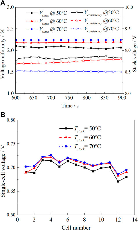
FIGURE 5. Effect of stack operation temperature. (A) Voltage uniformity, (B) Voltage distribution.
When the stack operating temperature decreases, the outlet gas condensation removes less gaseous water, resulting in the collection of liquid water in the channel, thus worsening the “flooding” phenomenon. The water is not actively drained inside the full dead-end condensing stack, resulting in uneven water distribution inside the stack. Some single cells produce unstable drainage due to gravity, resulting in significant differences in the voltage of every single cell, and the voltage uniformity is worse.
Figure 5B presents the voltage distribution of 13 single cells at different stack temperature conditions. The fluctuation of the single-cell voltage decreases with the increase of the stack temperature while the stack voltage increases. A higher stack operating temperature is suggested for the PEMFC stack (with cathode moisture condensation) to ensure a higher stack output efficiency and improve stack voltage uniformity.
3.3 Effect of Condensation Temperature on Voltage
Figure 6A shows the stack voltage of the PEMFC stack (with cathode moisture condensation) under different condensation temperatures and a gas pressure of 50 kPa and a stack temperature of 60°C. The performance of the PEMFC stack has been improved to different degrees, with higher output voltages obtained at the outlet gas condensation temperatures of 5 and 10°C. Figure 6B shows the stack voltage and voltage uniformity data at a pressure of 50 kPa, stack temperature of 60°C, and 500 mA cm−2 current density. The voltage uniformity at the cathode outlet gas condensation temperature of 10°C is lowest at 1.5%; it is significantly better than the uniformity at other outlet gas condensation temperatures. There is no significant difference in the voltage uniformity of the stack at other condensing temperatures.
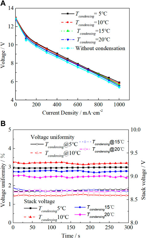
FIGURE 6. Effect of cathode moisture condensation temperature. (A) Stack voltage, (B) Voltage uniformity.
In Figure 6B, compared the PEMFC stack (without cathode moisture condensation) to the PEMFC stack (with condensation), the average stack voltage increases by 1.38% when the condensation temperature is 5°C. The average stack voltage increases by 2.64% when the outlet gas condensation temperature is 10°C; it increases 1.28% when the outlet gas condensation temperature is 15°C and 0.07% when the outlet gas condensation temperature is 20°C. The performance improvement is most evident when the PEMFC cathode outlet gas condensation temperature is at 10°C. When the PEMFC cathode outlet gas condensation temperature is 20°C, this is very close to the environment temperature of 21.3°C; thus, barely any improvement has been observed. When the condensation temperature is lower, it demonstrates the water removal performance. When the temperature is lower than 10°C, the water vapor in the stack condenses at the outlet and starts to accumulate, which causes the ‘flooding’ phenomenon and deteriorates the voltage uniformity.
Figure 7 shows the temperature distribution when the outlet gas is condensed at 5°C. The left side of the picture is the cooling water inlet, and the bottom side is the condenser position. The temperature at the cooling water inlet position is the lowest, reaching 46.5°C, the temperature difference between the lowest and highest is about 10°C. Operating the PEMFC stack at a relatively low condensation temperature of 5°C increases both the voltage and temperature distribution’s non-uniformity. This paper recommends the 10°C as the cathode outlet gas condensation temperature for the stable operation of the PEMFC.
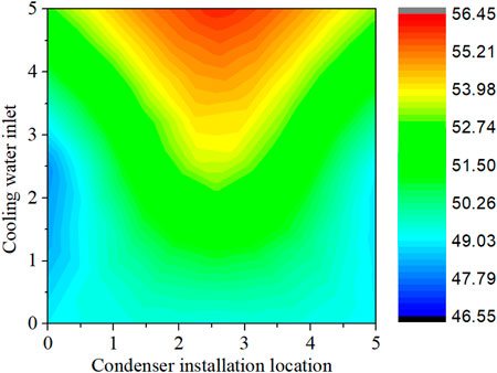
FIGURE 7. Cell temperature distribution.
3.4 Transient Performance at Start-Up/Shut-Down Conditions
Figure 8A presents the voltage uniformity of the PEMFC stack (with cathode moisture condensation) at the start-up condition. It is for different cathode outlet gas condensation temperatures under the operating conditions of current density 500 mA cm−2, gas pressure 50kPa, and stack operating temperature 60°C. In Figure 8A, the maximum voltage uniformity at different condensation temperatures of 5, 10, 15, and 20°C are 8.0, 5.6, 5.5, and 4.0%, respectively. The voltage uniformity value decreases as the condensation temperature increases; the voltage distribution becomes more uniform. When the condensing temperature reaches 5°C, the stack uniformity is more than 8%. This indicates that the stack’s operating condition significantly deteriorates. Therefore, when applying the cathode moisture condensation technology to the PEMFC stack at the start-up conditions, it is recommended that the minimum outlet gas condensation temperature should be equal to or higher than 10°C.
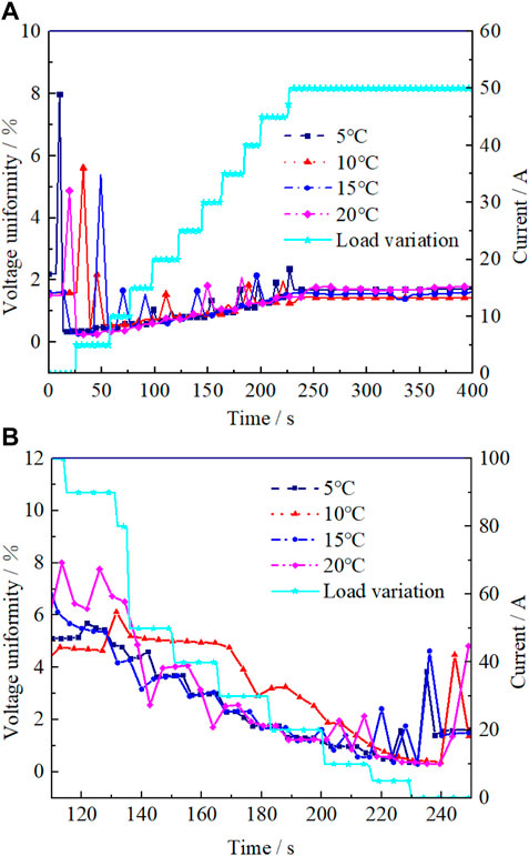
FIGURE 8. Voltage uniformity at dynamic conditions. (A) Start-up, (B) Shutdown conditions.
Figure 8B presents the voltage uniformity of the PEMFC stack (with cathode moisture condensation) at the shutdown condition. The maximum values of voltage uniformity during the shutdown are 4.0, 4.2, 4.3, and 4.5% for different condensation temperatures of 5, 10, 15, and 20°C, respectively. The stack voltage uniformity fluctuates less during the shutdown process when the condensation temperature varies. Results show that the lower condensation temperatures are more beneficial for the uniformity of the cell voltage distribution during the shutdown.
Figure 9A shows the temperature uniformity of the PEMFC stack for condensing on-off fan operation at 500 mA cm−2, 50kPa gas pressure, 60°C stack temperature, and 5°C condensation temperature. Each jump in the temperature uniformity result represents the turned-on of the condensing fan during the experiment. Figure 9B shows the relationship between voltage uniformity, single-cell temperature uniformity, and stack voltage during this process. In Figure 9B, when the single-cell temperature uniformity spikes at points A-H, both the corresponding voltage and voltage uniformity respond simultaneously. This indicates that the fluctuations in voltage and voltage uniformity are influenced by the on-off operation of the condensing fan; this leads to a dramatic drop in temperature within the stack and changes in temperature distribution within the stack, resulting in performance fluctuations. It is suggested an operation strategy that minimizes the condensing fan on-off operation shall be further developed for future work.
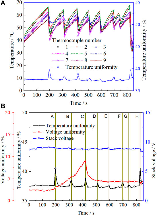
FIGURE 9. Effect of condensing fan on-off operation. (A) Temperature and temperature uniformity, (B) Stack voltage, voltage uniformity and temperature uniformity.
4 Conclusion
This paper investigates the impact of a self-water-removal technology (cathode moisture condensation) on PEMFC stack’s voltage behavior improvement. The experimental results of the output voltage response and single-cell voltage uniformity during the fuel cell steady-state and start-up/shutdown operations were measured and analyzed. The research shows that the optimal condensation temperature for full dead-ended condensing PEMFC is 10°C at both steady-state and transient operation. Compared to conventional PEMFC, applying the cathode moisture condensation technology to the PEMFC stack increases the stack voltage by 6% and decreases the voltage uniformity by up to 30%. This self-water-removal technology effectively improves the stack’s voltage uniformity, increasing the stack’s durability. It is also suggested an operation strategy that minimizes the condensing fan on-off operation shall be further developed for future work.
Data Availability Statement
The raw data supporting the conclusions of this article will be made available by the authors, without undue reservation.
Author Contributions
HP: Methodology, Writing Original Draft. CX: Conceptualization. LX: Resources, Writing-Review and Editing. ZT: Supervision.
Funding
This work was supported by the Natural Science Foundation of Hubei Province (No. 2020CFA040), the National Natural Science Foundation of China (No. 52076096) and Wuhan Applied Foundational Frontier Project (No. 2020010601012205).
Conflict of Interest
The authors declare that they have no known competing financial interests or personal relationships that could have appeared to influence the work reported in this paper.
Publisher’s Note
All claims expressed in this article are solely those of the authors and do not necessarily represent those of their affiliated organizations, or those of the publisher, the editors and the reviewers. Any product that may be evaluated in this article, or claim that may be made by its manufacturer, is not guaranteed or endorsed by the publisher.
References
Asghari, S., Ashraf Khorasani, M. R., and Dashti, I. (2016). Investigation of Self-Humidified and Dead-Ended Anode Proton Exchange Membrane Fuel Cell Performance Using Electrochemical Impedance Spectroscopy. Int. J. Hydrogen Energy 41, 12347–12357. doi:10.1016/j.ijhydene.2016.05.133
Baldi, F., Wang, L., Pérez-Fortes, M., and Maréchal, F. (2019). A Cogeneration System Based on Solid Oxide and Proton Exchange Membrane Fuel Cells with Hybrid Storage for Off-Grid Applications. Front. Energy Res. 6, 139. doi:10.3389/fenrg.2018.00139
Cha, D., Yang, W., and Kim, Y. (2019). Performance Improvement of Self-Humidifying PEM Fuel Cells Using Water Injection at Various Start-Up Conditions. Energy 183, 514–524. doi:10.1016/j.energy.2019.06.154
Chen, K., Yh, A., Cj, B., Xp, B., and Dong, H. C. (2021). Experimental Investigation on Statistical Characteristics of Cell Voltage Distribution for a PEMFC Stack under Dynamic Driving Cycle. Int. J. Hydrogen Energy. 46, 38469–38481. doi:10.1016/j.ijhydene.2021.09.092
Hu, Z., Liangfei, X., Jianqiu, L., Xin, X., Ziyou, S., Minggao, O., et al. (2019). The Uniformity and Consistency Analysis of a Fuel Cell Stack with Multipoint Voltage-Monitoring Method. Energy Procedia 158, 2118–2125. doi:10.1016/j.egypro.2019.01.486
Jang, J. H., Yan, W. M., Chiu, H. C., and Lui, J. Y. (2015). Dynamic Cell Performance of kW-Grade Proton Exchange Membrane Fuel Cell Stack with Dead-Ended Anode. Appl. Energy 142, 108–114. doi:10.1016/j.apenergy.2014.12.073
Li, C., Si, D., Liu, Y., Zhang, J., and Liu, Y. (2021). Water Management Characteristics of Electrospun Micro-porous Layer in PEMFC under Normal Temperature and Cold Start Conditions. Int. J. Hydrogen Energy 46, 11150–11159. doi:10.1016/j.ijhydene.2020.05.271
Lin, R., Ren, Y. S., Lin, X. W., Jiang, Z. H., Yang, Z., and Chang, Y. T. (2017). Investigation of the Internal Behavior in Segmented PEMFCs of Different Flow Fields during Cold Start Process. Energy 123, 367–377. doi:10.1016/j.energy.2017.01.138
Lin, R., Yuanming, W., Yi, L., Xuwei, L., Sichuan, X., and Jianxin, M. (2014). Internal Behavior of Segmented Fuel Cell during Cold Start. Int. J. Hydrogen Energy. 39, 16025–16035. doi:10.1016/j.ijhydene.2013.12.083
Liu, P., Xu, S., Fu, J., and Liu, C. (2020). Experimental Investigation on the Voltage Uniformity for a PEMFC Stack with Different Dynamic Loading Strategies. Int. J. Hydrogen Energy 45, 26490–26500. doi:10.1016/j.ijhydene.2020.05.070
Moçotéguy, P., Ludwig, B., Beretta, D., and Pedersen, T. (2020). Study of the Impact of Water Management on the Performance of PEMFC Commercial Stacks by Impedance Spectroscopy. Int. J. Hydrogen Energy. 45, 16724–16737. doi:10.1016/j.ijhydene.2020.04.139
Ozen, D. N., Timurkutluk, B., and Altinisik, K. (2016). Effects of Operation Temperature and Reactant Gas Humidity Levels on Performance of PEM Fuel Cells. Renew. Sustain. Energy Rev. 59, 1298–1306. doi:10.1016/j.rser.2016.01.040
Pei, H., Bangbang, M., Huawei, C., Chenguang, X., and Zhengkai, T. (2021). Effect of Cathode Moisture Condensation on Temperature Distribution Characteristics of Dead-Ended Proton-Exchange Membrane Fuel Cell Stack. Int. J. Energy Res. 42, 4770–4780. doi:10.1002/er.7471
Pérez-Page, M., and Pérez-Herranz, V. (2009). Effect of the Operation and Humidification Temperatures on the Performance of a PEM Fuel Cell Stack. Meet. Abstr. MA2009-02 (1), 905. doi:10.1149/ma2009-02/10/905
Santarelli, M. G., and Torchio, M. F. (2007). Experimental Analysis of the Effects of the Operating Variables on the Performance of a Single PEMFC. Energy Convers. Manag. 48, 40–51. doi:10.1016/j.enconman.2006.05.013
Stephen, A. J., Rees, N. V., Mikheenko, I., and Macaskie, L. E. (2019). Platinum and Palladium Bio-Synthesized Nanoparticles as Sustainable Fuel Cell Catalysts. Front. Energy Res. 7, 66. doi:10.3389/fenrg.2019.00066
Tang, W., Rui, L., Yuanming, W., Jingming, Z., and Jianxin, M. (2013). The Effects of Operating Temperature on Current Density Distribution and Impedance Spectroscopy by Segmented Fuel Cell. Int. J. Hydrogen Energy. 38, 10985–10991. doi:10.1016/j.ijhydene.2013.01.099
Wan, Z., Liu, J., Luo, Z., Tu, Z., Liu, Z., and Liu, W. (2013). Evaluation of Self-Water-Removal in a Dead-Ended Proton Exchange Membrane Fuel Cell. Appl. Energy 104, 751–757. doi:10.1016/j.apenergy.2012.12.008
Wan, Z. M., Wan, J. H., Liu, J., Tu, Z. K., Pan, M., and Liu, Z. C. (2012). Water Recovery and Air Humidification by Condensing the Moisture in the Outlet Gas of a Proton Exchange Membrane Fuel Cell Stack. Appl. Therm. Eng. 42, 173–178. doi:10.1016/j.applthermaleng.2012.02.045
Wang, B., Lin, R., Liu, D., Xu, J., and Feng, B. (2019). Investigation of the Effect of Humidity at Both Electrode on the Performance of PEMFC Using Orthogonal Test Method. Int. J. Hydrogen Energy 44, 13737–13743. doi:10.1016/j.ijhydene.2019.03.139
Wilberforce, T., Ijaodola, O., Khatib, F. N., Ogungbemi, E. O., El Hassan, Z., Thompson, J., et al. (2019). Effect of Humidification of Reactive Gases on the Performance of a Proton Exchange Membrane Fuel Cell. Sci. Total Environ. 688, 1016–1035. doi:10.1016/j.scitotenv.2019.06.397
Xia, Z., Bowen, W., Zirong, Y., Kangcheng, W., Qing, D., and Kui, J. (2019). Effect of Operating Conditions on Performance of Proton Exchange Membrane Fuel Cell with Anode Recirculation. Energy Procedia 158, 1829–1834. doi:10.1016/j.egypro.2019.01.428
Yang, Y., Zhang, X., Guo, L., and Liu, H. (2017). Mechanisms of Voltage Spikes and Mitigation Strategies for Proton Exchange Membrane Fuel Cells with Dead-Ended Anode under Pressure Swing Operation. Int. J. Hydrogen Energy 42, 28578–28587. doi:10.1016/j.ijhydene.2017.09.103
Yang, Z., Du, Q., Jia, Z., Yang, C., and Jiao, K. (2019). Effects of Operating Conditions on Water and Heat Management by a Transient Multi-Dimensional PEMFC System Model. Energy 183, 462–476. doi:10.1016/j.energy.2019.06.148
Keywords: dead-ended proton exchange membrane fuel cell, water management, voltage uniformity, dynamic characteristic, steady state
Citation: Pei H, Xiao C, Xing L and Tu Z (2022) Self-Water-Removal and Voltage Behavior Improvement of Dead-Ended Proton Exchange Membrane Fuel Cell Stack at Steady-State and Dynamic Conditions. Front. Energy Res. 10:902829. doi: 10.3389/fenrg.2022.902829
Received: 23 March 2022; Accepted: 16 May 2022;
Published: 06 June 2022.
Edited by:
Shijun Liao, South China University of Technology, ChinaReviewed by:
Dai Dang, Guangdong University of Technology, ChinaStefania Specchia, Politecnico di Torino, Italy
Copyright © 2022 Pei, Xiao, Xing and Tu. This is an open-access article distributed under the terms of the Creative Commons Attribution License (CC BY). The use, distribution or reproduction in other forums is permitted, provided the original author(s) and the copyright owner(s) are credited and that the original publication in this journal is cited, in accordance with accepted academic practice. No use, distribution or reproduction is permitted which does not comply with these terms.
*Correspondence: Lu Xing, bHUueGluZ0Bub3J0aHVtYnJpYS5hYy51aw==; Zhengkai Tu, dHprbHFAaHVzdC5lZHUuY24=