 Xin Ren1
 Jian Yang
 Wei Wang
- 1Huaneng Clean Energy Research Institute, Beijing, China
- 2Yunnan Branch of Huaneng Renewables Corporation Limited, Kunming, China
- 3North China Electric Power University, Beijing, China
In view of the fact that current wind farms are mostly multi-wind turbines and it is difficult to accurately control a single wind turbine because of its high dimension in the optimization solution process, the article proposes a reactive power and voltage coordinated control strategy suitable for doubly-fed wind farms. The strategy is mainly divided into three layers. The first is the group layer, which can obtain the reactive power compensation task of the entire group according to the current voltage and voltage indicators of the group collection station. The second is the field layer, in which according to the reactive power compensation tasks issued by the group layer, the reactive power tasks are allocated to each field area based on the tabu search algorithm or the equal margin method. The third is the equipment layer, which allocates equal margins in the area according to the reactive power compensation tasks assigned by the field layer. At the field layer, this article divides 66 wind turbines into five different field areas to solve the reactive power compensation distribution task according to the voltage sensitivity characteristics of the wind turbines on different feeders.
Introduction
In recent years, the installed capacity of wind power has been continuously improved, and the grid-connected technology of wind power has continuously reached maturity. However, compared with traditional thermal power generation, wind power generation is more unstable. It is easy to be affected by uncertain factors such as wind speed fluctuations, resulting in errors, and the control of reactive power and voltage has always been the focus of research (Chen et al., 2005; Chi et al., 2007; Chen et al., 2013). Due to the characteristics of local wind resources and the reverse distribution of power loads, wind farms (WFs) are generally built in areas far away from the load center (Yang et al., 2014a), resulting in wind power generation with the characteristics of clustering, radiation connection, and weak power grids (Cao et al., 2009).
At present, a key method to solve the problem of voltage stability in WFs is reactive power compensation. In a wind farm group, there are two main devices for reactive power compensation: one is the reactive power compensation device added to the wind farm booster station (Sun et al., 2003), and the other is a double-fed induction generator (DFIG). The reactive power compensation equipment mainly includes a mechanical switching capacitor bank, a static var compensator (SVC), a static var generator (SVG), and an on-load tap changer (OLTC), etc. Among them, the response speed of mechanical switching capacitor banks is generally slower (Tang et al., 2021) and SVG has faster response speed and smaller footprint than SVC (Xu et al., 2015), so SVG is currently more popular in the WFs. DFIG has become the most widely used model in megawatt wind turbines because it can realize active and reactive power decoupling control and has a smaller inverter capacity (Pena et al., 1996; Zhang et al., 2020). Most of them are in constant power factor operation mode or constant voltage operation mode (Cui et al., 2015).
Zhang et al. (2019) proposed a voltage coordination control strategy based on hierarchical model predictive control, which mainly focused on the problems caused by wind power fluctuations on voltage regulation. Sun et al. (2014) proposed a method to reserve margins for wind turbines. Tao et al. (2018) proposed a reactive power optimization strategy for distribution networks based on particle swarm optimization, and the objective function is to minimize voltage fluctuation and network loss. Cai et al. (2018) proposed a multi-objective reactive power and voltage control method for wind farms. While meeting the voltage requirements of the collective bus, the voltage distribution in the WFs is also optimized. Shao et al. (2009) proposed a control method using a reduced-order Jacobian matrix and conducted relevant research on the voltage support capability of different wind farms after they are connected to local areas.
All of the aforementioned studies have provided useful insights into the reactive power and voltage control of wind farms. However, the wind farm group is generally in a multi-wind turbine mode, and it is not only time-consuming but also difficult to accurately calculate the reactive power output of each wind turbine generator (WTG). Therefore, this article comprehensively considers the aforementioned factors and proposes a layered and zonal-coordinated control strategy for wind farm group reactive power and voltage. The WTGs in the farm group are divided into different regions, which reduces the dimension of the algorithm calculation. When the WF receives the reactive power compensation task, based on the tabu search algorithm, the reactive power compensation amount of each field area is calculated with the minimum nodal voltage index and the maximum margin index as the objective function. After each field area receives the reactive power compensation task, it adopts the equal margin method to allocate the reactive power task within the field area, which can not only ensure that each WTG does not exceed the limit but also ensure that the WF has the largest reactive power reserve margin.
Reactive Voltage Coordination Control Strategy Framework of WFs
The schematic diagram of the proposed control strategy is shown in Figure 1.
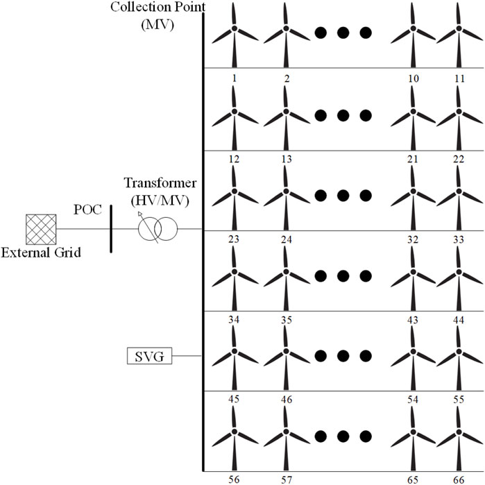
FIGURE 1. Strategy mechanism for reactive power control of wind farms.
In Figure 1, one WF is in the form of six feeders, each of which is in the form of 11 WTGs. All feeders are connected to a collection point with a nominal voltage of 35 KV. The collection point is then connected to the external grid through the transformer and point of connection (POC). HV/MV means high voltage/medium voltage.
The control center receives the reactive power information of the WFs and the voltage information of the collection point in real time and calculates the reactive power compensation of the current moment according to the relevant information. If the reactive power limit for the safe operation of the WFs has been exceeded, the excess part will be shared with SVG. If not, then the control center distributes the reactive power compensation amount to the five field areas after the tabu search algorithm calculation and finally distributes the reactive power compensation amount to each WTG in the area after equal margin calculation.
Calculation of Reactive Power Demand
According to the voltage information of the collection point in the adjacent measurement period and the reactive power information of the WFs in the adjacent measurement period, the control sensitivity of the reactive power relative to the collection point voltage can be estimated as
where
Then, it can be concluded that the reactive power compensation of the WFs at the current moment is
where
Reactive Power Capacity of DFIG
Reactive Power Capacity of the Stator
The reactive power capacity of DFIG should be considered first when the control strategy of DFIG participating in reactive power regulation is formulated and implemented. Through the analysis of DFIG operation characteristics, the reactive power capacity of DFIG is mainly restricted by the active power output, unit capacity, and current limit of the converter, etc., that is, the reactive power capacity of DFIG is jointly determined by the stator and grid side converter.
When the active power
where
Reactive Power Capacity of the Grid-Side Converter
The reactive power capacity of the grid-side converter is mainly determined by the limit capacity of the grid-side converter and the slip rate of WTG. The limit of its reactive power is
where
Therefore, by comprehensively considering the reactive power capacity of the stator and grid-side converter, the limit of the reactive power capacity of a single DFIG can be obtained by
The Reactive Power Compensation Value of Each Field Area Based on Tabu Search Algorithm
Partition of a Wind Farm
After receiving the task of reactive power compensation, the control center will distribute the reactive power compensation. However, wind farms generally adopt the mode of multi-WTGs, so it is very time-consuming to calculate the reactive power compensation of each WTG. Therefore, in this article, according to the voltage “sensitivity” characteristic of WTGs with different feeders, the WTGs in the wind farm are partitioned, which not only ensures the accuracy but also greatly saves the calculation time.
The voltage “sensitivity” characteristic refers to that on a single feeder, when different WTGs send out the same reactive power, the voltage of the collection point is different, as is shown in Figure 2.
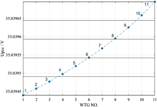
FIGURE 2. Sensitivity of voltage.
Therefore, according to the voltage “sensitivity” characteristics, the first three WTGs on the six feeders and the eight WTGs at the back are divided in pairs into five fields, from 1 to 5. After partition processing, the optimization dimension of the algorithm is reduced from the original 66 dimensions to the present 5 dimensions, which greatly saves the calculation time.
Tabu Search Algorithm
The tabu search algorithm (TS) (Venugopal and Narendran, 1992; Logendran, 1993; Gupta et al., 1995) was first proposed by Glover. As an extension to the local neighborhood search algorithm, it is a global step-by-step optimization algorithm and a simulation of the human intelligence process. The key points of this algorithm are neighborhood structure, tabu feature, tabu table, and contempt principle. The neighborhood structure is used to search data in the neighborhood. The tabu feature and tabu table are designed to avoid roundabout search. The contempt principle is tantamount to rewarding good status, a relaxation of tabu strategies.
Since TS with the flexible memory function and contempt principle and in the process of search process, inferior solutions can also be accepted, the algorithm has strong ability of mountain climbing and can jump out when searching local optimal solution, then turn to other area to search for the global optimal solution, so that to increase the probability of obtaining the best global optimal solution. The main implementation process of TS is as follows (Lei and Yan):
1) Define the initial solution: the initial solution of TS can be randomly generated or can use the solution which is based on other methods. In this article, the solution obtained by the margin method is used as the initial solution.
2) Construct the neighborhood structure of the solution: the design of the neighborhood structure generally varies from problem to problem. In this article, adaptive weight coefficients are used to generate random neighborhood solutions.
3) Generation of candidate solutions: first, determine the number of candidate solutions, and then select the optimal candidate solutions.
4) Tabu table and its length: based on the principle of first in, first out, the length of the tabu table in this article is adaptive.
5) Contempt principle: a solution will ignore its tabu characteristics and directly be selected as the current solution when it is superior to the current optimal solution.
6) Termination condition: the termination condition of this article is that either the number of iterations ends or the optimal solution remains unchanged in 50 iterations.
The Reactive Power Compensation of Each WTG
In actual WFs, the reactive power compensation device is generally equipped, such as SVG, SVC, and OLTC. This article aims to maximize the reactive power regulation ability of DFIG, so it gives priority to DFIG. However, considering that the closer the reactive power of a DFIG is to the limit value, the more unfavorable it is to the life of the DFIG; this article reserves a 50% reactive power limit margin for all WTGs as the safe operation limit. In this article, TS algorithm is used to find the optimal distribution solution, and then the equal margin method is used within each field. The distribution method of DFIG and SVG in each field is as follows:
1) If the reactive power compensation is within the safe operating reactive power limit of DFIG,
2) Else,
where
The Control Model of WFs
Objective Function
Nodal Voltage Index
Taking the actual operating conditions of a wind farm as an example, when the WTGs run at a constant power factor of 0.95, the voltage distribution of WTGs on different feeders is shown in Figure 3.
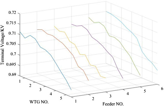
FIGURE 3. Terminal voltage distribution of WTG.
As can be seen from Figure 3, due to the different reactive power output and feeder cable length of WTGs inside the wind farm, there will be certain differences in terminal voltage. In order to better investigate the voltage stability of each generator, the nodal voltage index is established as follows (Zhao et al., 2018):
where
Margin Index
In order to ensure the safety of WFs in operation, the margin index of WFs is defined as follows:
Above all, the objective function is:
where
Constraint Condition
Equality Constraint
The most basic equality constraint in wind farms is the power flow constraint equation (Yang et al., 2014b):
where
In addition, the total amount of reactive power output by the DFIG should be consistent with the reactive power demand, so the constraint of the reactive power equation is:
where
Inequality Constraints
The inequality constraints of reactive voltage control in WFs mainly include upper and lower limits of node voltage, upper and lower limits of reactive power output of DFIG, and upper and lower limits of SVG output, represented as follows:
Control Process
The flow chart of the reactive voltage control strategy in the wind farm which is proposed in this article is shown in Figure 4.
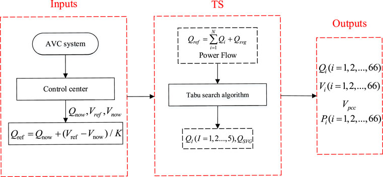
FIGURE 4. Flow chart for reactive power and voltage control of WFs.
The control center of WFs receives the WTG operation mode, and grid nominal voltage forms the system operator. Then, according to the voltage of the collection point and the current reactive power value of WFs monitored by the control center, the current reactive power demand of WFs is determined. If the reactive power demand exceeds the limit, the excess part is allocated to the SVG, and all WTGs are in full operation. If not, according to the demarcated field area, the reactive power compensation of each field is solved by TS algorithm, and then the equal margin method is used to determine the reactive power compensation of each WTG in the WF.
Optimization Result Analysis
System Description and Parameter Settings
This article takes the wind farm shown in Figure 1 as an example to verify the feasibility and effectiveness of this strategy. The WFs consist of 66 1.5-MW DFIGs, which are connected to the collection point through six feeder cables in the WF, and 11 DFIGs are distributed on each feeder. Each DFIG is connected to the feeder cable via its own box transformer, and the SVG device is installed at the transformer of the collection point. The collection point is then connected to the external grid through the transformer and POC.
In this system, the residual reactive power reserve limit of each DFIG is 50%, the reactive power output limit of SVG is -15 ∼30 MW, and the voltage index is 1.0 pu. In TS algorithm, the weight coefficient of the nodal voltage index is 0.6 and that of the margin index is 0.4.
Control Effect Analysis
In order to compare and analyze the influence of different control types on the system, three control types are set up in this article for comparative analysis to verify the effectiveness and feasibility of the strategy.
Type 1. The wind farm does not carry out reactive power compensation. All WTGs inside the wind farm operate at a constant power factor of 0.95.
Type 2. The wind farm is not partitioned. After the reactive power demand is calculated by the control center, all WTGs in the WF are allocated with an equal margin method. The control period is 10 min.
Type 3. The strategy described in this article is adopted. After the control center calculates the reactive power demand, the TS algorithm is used to solve the reactive power compensation of each field area, and then the reactive power compensation amount of each DFIG in the WF is calculated by the equal margin method. The control period is 10 min.
The comparison figure of the three control methods is shown as Figures 5–9:
As can be seen from all the aforementioned pictures and Table 1, in the case of the same WF active power output shown in Figure 5 and Figure 6, the voltage amplitude of the collection point is lower in Type 3 than other types. Furthermore, the nodal voltage index and margin index are also optimized downward in Type 3 which is shown in Figure 7, Figure 8, and Figure 9. Finally, not only the average value but also the standard deviation in the WTGs’ terminal voltage of Type 3 has better results than that of other types. Above all, Type 3 is significantly improved compared with type 2 and type 1, which proves the effectiveness of the strategy proposed in this article.
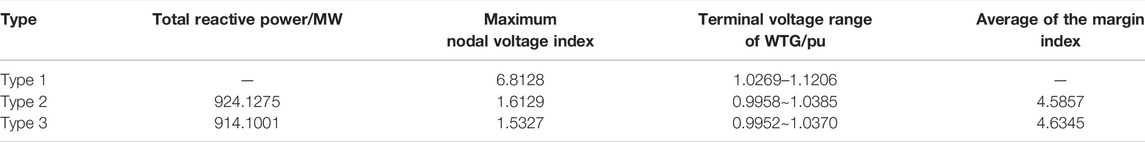
TABLE 1. Comparison of optimized results by different control types.
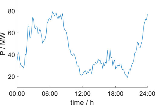
FIGURE 5. Active power output.
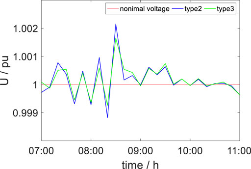
FIGURE 6. Voltage amplitude of the collection point.
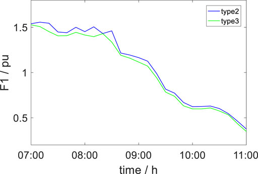
FIGURE 7. Nodal voltage index.
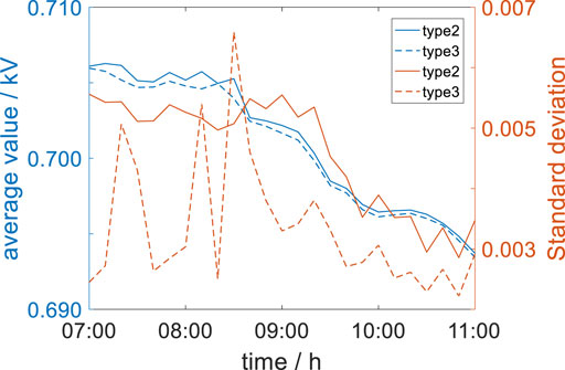
FIGURE 8. Terminal voltage of WTG.
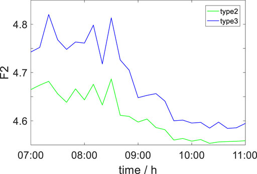
FIGURE 9. Margin index.
Conclusion
In this article, one coordinative strategy based on the TS algorithm for reactive power and voltage control of wind farms is proposed and successfully applied to optimize the operation of power systems with DFIGs. Compared with the existing strategies, we conclude that: 1) the distribution of reactive power demand after partition not only does not reduce the control precision but also achieves greater optimization effect, with smaller voltage fluctuation and less power loss than the equal margin distribution. 2) After reactive power compensation, the voltage of the collection point is always near the standard value, which proves that reactive power compensation plays a decisive role in voltage stability. 3) Comparing the nodal voltage index and the margin index, it can be concluded that the TS algorithm has strong optimization ability and can be used in the calculation of reactive power compensation distribution in wind farms.
Data Availability Statement
The original contributions presented in the study are included in the article/supplementary material; further inquiries can be directed to the corresponding author.
Author Contributions
All authors listed have made a substantial, direct, and intellectual contribution to the work and approved it for publication.
Funding
This study received funding from Huaneng Renewables Corporation Limited (HNRKJ-2020-03).
Conflict of Interest
RX, WH, WQ, LB, and WH were employed by the company Huaneng Clean Energy Research Institute. WZ was employed by the company Yunnan Branch of Huaneng Renewables Corporation Limited.
The remaining authors declare that the research was conducted in the absence of any commercial or financial relationships that could be construed as a potential conflict of interest.
Publisher’s Note
All claims expressed in this article are solely those of the authors and do not necessarily represent those of their affiliated organizations, or those of the publisher, the editors, and the reviewers. Any product that may be evaluated in this article, or claim that may be made by its manufacturer, is not guaranteed or endorsed by the publisher.
References
Cai, Y., Zheng, L., and Xu, C. (2018). Wind Farm Reactive Voltage Coordinated Control Aiming at the Stability of Grid-Connected Point Voltage and Terminal Voltage. Electr. Power Autom. Equip. 38 (08), 166–173. doi:10.16081/j.issn.1006-6047.2018.08.024
Cao, J., Zhang, R., Lin, G., Wang, H., and Qiu, J. (2009). Variable-Speed Constant-Frequency Doubly-Fed Wind Farm Voltage Control Strategy. Automation Electr. Power Syst. 33 (4), 87–91. doi:10.3321/j.issn:1000-1026.2009.04.019
Chen, H., Zhang, Y., Min, Y., Qiao, Y., and Lu, Z. (2013). Graded Voltage Control Strategy for Clustering Wind Farms Based on Doubly-Fed Induction Generators. Automation Electr. Power Syst. 4, 7–13. doi:10.7500/AEPS201110004
Chen, S., Shen, H., Zhang, Y., Pu, G., and Yin, Y. (2005). Researches on the Compensation and Control of Reactive Power for Wind Farms Based on Genetic Algorithm. Proc. CSEE 25 (8), 1–6. doi:10.3321/j.issn:0258-8013.2005.08.001
Chi, Y., Liu, Y., Wang, W., Chen, M., and Dai, H. (2007). Study on Impact of Wind Power Integration on Power System. Power Syst. Technol. 31 (3), 77–81. doi:10.3969/j.issn.2095-2104.2016.10.989
Cui, Y., Peng, L., Zhong, W., Yan, G., Yin, J., and Pu, R. (2015). Coordination Strategy of Reactive Power Control on Wind Farms Based Doubly Fed Induction Generator. Proc. CSEE 35 (17), 4300–4307. doi:10.13334/j.0258-8013.pcsee.2015.17.003
Gupta, Y. P., Gupta, M. C., Kumar, A., and Sundram, C. (1995). Minimizing Total Intercell and Intracell Moves in Cellular Manufacturing: A Genetic Algorithm Approach. Int. J. Comput. Integr. Manuf. 8 (2), 92–101. doi:10.1080/09511929508944633
Lei, D., and Yan, X. Multi-Objective Intelligent Optimization Algorithm and its Application. Beijing: Science Press.
Logendran, R. (1993). A Biary Integer Programming Approach for Simultaneous Machine-Part Grouping in Cellular Manufacturing Systems. Comput. Industrial Eng. 24, 329–336. doi:10.1016/0360-8352(93)90030-2
Pena, R., Clare, J. C., and Asher, G. M. (1996). Doubly Fed Induction Generator Using Back-To-Back PWM Converters and its Application to Variable-Speed Wind-Energy Generation. IEE Proc. Electr. Power Appl. 143 (3), 231–241. doi:10.1049/ip-epa:19960288
Shao, Y., Chen, N., Zhu, L., and Wang, W. (2009). Reduced Jacobian Matrix Based Method to Assess Local Static Reactive Power/Voltage Supporting Ability of Interconnected Wind Farm. Power Syst. Technol. 33 (02), 14–19. doi:10.1016/j.apm.2007.10.019
Sun, T., Wang, W., Dai, H., and Yang, Y. (2003). Voltage Fluctuation and Flicker Caused by Wind Power Generation. Power Syst. Technol. 2003 (12), 62–66+70. doi:10.3321/j.issn:1000-3673.2003.12.014
Sun, W., Fu, R., and Chen, Y. (2014). Coordinated Reactive Power and Voltage Control of Doubly-Fed Wind Farms with Reactive Power Margins. Electr. Power Autom. Equip. 34 (10), 81–85. doi:10.3969/j.issn.1006-6047.2014.10.013
Tang, T., Ma, M., Ouyang, J., Liang, X., Wang, Y., and Li, M. (2021). Reactive Power and Voltage Coordination Control Strategy of DFIG-Based Wind Farm Under Wind Speed Variations. Guangdong Electr. Power 34 (05), 19–27. doi:10.3969/j.issn.1007-290X.2021.005.003
Tao, Z., Gu, H., and Ding, X. (2018). Study on Multi-Objective Reactive Power Optimization Based on Voltage Stability. Smart Power 46 (10), 63–70. doi:10.3969/j.issn.1673-7598.2018.10.011
Venugopal, V., and Narendran, T. T. (1992). A Genetic Algorithm Approach to the Machine-Component Grouping Problem with Multiple Objectives. Comput. Industrial Eng. 22 (4), 469–480. doi:10.1016/0360-8352(92)90022-c
Wang, Q., Yuan, Y., Ning, C., Wu, H., and Wu, S. (2012). The Cooperating Distribution Methods of Reactive Power in Multi-Wind Farms Integrated Region. Power Syst. Prot. Control 40 (24), 76–83. doi:10.7667/j.issn.1674-3415.2012.24.013
Wang, S., Li, G., and Zhou, M. (2014). The Reactive Power Adjusting Mechanism & Control Strategy of Doubly Fed Induction Generator. Proc. CSEE 34 (16), 2714–2720. doi:10.13334/j.0258-8013.pcsee.2014.16.023
Xu, F., Guo, Q., Sun, H., Lan, H., Liu, H., and Liu, X. (2015). Automatic Voltage Control of Wind Farm Based on Model Predictive Control Theory. Automation Electr. Power Syst. 39 (07), 59–67. doi:10.7500/AEPS20140417004
Yang, S., Wang, W., Chun, L., and Huang, Y. (2014). Coordinative Strategy for Reactive Power and Voltage Control of Wind Farms Cluster Considering Wind Power Fluctuation. Proc. CSEE 34 (28), 4761–4769. doi:10.13334/j.0258-8013.pcsee.2014.28.003
Yang, S., Wang, W., Chun, L., and Huang, Y. (2014). Coordinative Strategy of Reactive Power and Voltage Control for Improving Static Voltage Stability of Wind Power Centralized System. Power Syst. Technol. 38 (05), 1250–1256. doi:10.13335/j.1000-3673.pst.2014.05.019
Zhang, X., Zhang, Y., Ran, F., Chen, L., and Xu, D. (2020). Control Strategy of Grid Voltage Disturbance Compensation for Doubly-Fed Wind Turbines in Weak Grid. Automation Electr. Power Syst. 44 (06), 146–154. doi:10.7500/AEPS20190216002
Zhang, Z., Wang, C., Dong, X., Yang, M., Liang, J., and Zhang, H. (2019). Wind Farm Voltage Coordinated Control Strategy Based on Hierarchical Model Predictive Control. Automation Electr. Power Syst. 43 (11), 34–42+94. doi:10.7500/AEPS20180717014
Keywords: wind farms, reactive power (Q), tabu search algorithm, equal margin method, voltage control
Citation: Ren X, Wang H, Wang Z, Wang Q, Li B, Wu H, Yang J and Wang W (2022) Reactive Voltage Control of Wind Farm Based on Tabu Algorithm. Front. Energy Res. 10:902623. doi: 10.3389/fenrg.2022.902623
Received: 23 March 2022; Accepted: 04 May 2022;
Published: 15 June 2022.
Edited by:
Junhui Li, Northeast Electric Power University, ChinaCopyright © 2022 Ren, Wang, Wang, Wang, Li, Wu, Yang and Wang. This is an open-access article distributed under the terms of the Creative Commons Attribution License (CC BY). The use, distribution or reproduction in other forums is permitted, provided the original author(s) and the copyright owner(s) are credited and that the original publication in this journal is cited, in accordance with accepted academic practice. No use, distribution or reproduction is permitted which does not comply with these terms.
*Correspondence: Jian Yang, bmNlcHV5akBuY2VwdS5lZHUuY24=