 Xiaozhuo Xu
 Wei Qian
 Xiangwei Guo
94% of researchers rate our articles as excellent or good
Learn more about the work of our research integrity team to safeguard the quality of each article we publish.
Find out more
ORIGINAL RESEARCH article
Front. Energy Res., 25 May 2022
Sec. Electrochemical Energy Storage
Volume 10 - 2022 | https://doi.org/10.3389/fenrg.2022.901811
To reduce the impact of series battery pack inconsistency on energy utilization, an active state of charge (SOC) balancing method based on an inductor and capacitor is proposed. Only one inductor and one capacitor can achieve a direct transfer of balanced energy between the highest power cell and the lowest power cell. This method has the characteristics of a simple structure, small size, simple control, fast balancing speed, and low topology cost. First, the topology, working principle, parameter design, and control strategy of the proposed balancing method are explained. Second, the characteristics of the speed and efficiency are analyzed through the simulation models, and the advantages of its low topology cost and simple control are explained. Finally, by building an experimental platform for a four-cell series battery pack, the effectiveness of the new balancing method in the charging/discharging process and the dynamic process of the battery pack is verified. After the end of the balancing, the SOC difference is less than 4%.
Lithium-ion batteries are widely used in the power systems of new energy vehicles (EVs). Due to the low cell voltage and capacity, battery cells must be connected in series and parallel to form a battery pack in order to meet application requirements (Tang et al., 2020; Cao and Abu Qahouq, 2021; Xia and Abu Qahouq, 2021; Wang et al., 2022). With the increase in the service time of the battery pack, the inevitable inconsistency between the cells will have a serious impact on the energy utilization rate and the cycle life of the battery pack. An effective balancing method must be introduced to alleviate the inconsistency of the battery pack (Ouyang et al., 2018; Shi et al., 2021). The influence of inconsistency on the series battery pack is more prominent than that of the parallel battery pack (Ye et al., 2019), and the state of charge (SOC) can reflect the inconsistency of the cell in real time compared with the voltage and capacity (Zhang et al., 2017). This article focuses on the SOC balancing method of the series battery pack.
According to the different energy transfer modes, the balancing methods are mainly divided into passive balancing and active balancing (Turksoy et al., 2020; Ghaeminezhad et al., 2021). Among them, the active balancing method uses energy storage devices, such as inductors, capacitors, and transformers, to transfer energy. It has the characteristics of a perfect balancing function and high efficiency, which is a prominent area in the research of balancing methods. The balancing method based on inductive energy storage (Xu et al., 2021; Chen et al., 2021; Ding et al., 2020) has a higher accuracy, but it often requires more inductors or switch tubes and is larger in size. The capacitor energy storage balancing method (Shang et al., 2017; Ye et al., 2017; Shang et al., 2018) has the advantages of a small volume and easy control. When the voltage difference between the balancing object and the capacitor changes from large to small, the balancing speed changes from fast to slow, resulting in a low balancing accuracy of capacitor energy storage balancing. In addition, the voltage changes drastically at the initial moment of the capacitor energy storage balancing. If the voltage is used as the balancing index, it will easily lead to overbalancing or underbalancing. The transformer energy storage balancing method (Shang et al., 2020a; Tavakoli et al., 2020; Guo et al., 2021a; Liu et al., 2021a; Conway, 2021; Nazi and Babaei, 2021) has high efficiency and is easy to isolate. However, the winding transformer design is complicated and has a peak voltage. Improper handling may cause serious safety hazards.
In combination with the characteristics of high accuracy of inductive energy storage balancing and a high speed of capacitive energy storage balancing when the voltage difference is large, topologies based on inductor–capacitor (LC) energy storage have gradually become a prominent area in the research of active balancing methods in recent years. The topology proposed by Wei et al. (2021) is based on LC for energy transfer, using fewer energy storage devices; however, it requires designing a dual-winding transformer and the number of switch tubes is large. The topology proposed by Zou et al. (2021) is similar to Wei et al. (2021) in terms of balancing principles. Although the number of switching tubes is reduced, the number of capacitors and windings is significantly increased. Liu et al. (2021b) use LC parallel resonance to eliminate the inrush currents, thereby improving the balancing efficiency. However, each cell must be equipped with four switching tubes and an LC series circuit, which is not conducive to reducing the volume and cost of the balancing system. The energy storage unit proposed by Raeber et al. (2021) contains an inductor, two capacitors, and four switching tubes, where each cell needs to be equipped with two switching tubes. Theoretically, this has a higher balancing efficiency, but the energy storage unit has a larger number of switch tubes, and the control complexity is higher. References (Lee et al., 2015; Shang et al., 2020b; Yu et al., 2020) use an LC series resonant circuit and adopt soft switching technology to switch the charge and discharge loop of the balanced object, which greatly reduces the switching loss of the balancing process. However, the control process is too complicated, and each switch tube needs to accurately calculate the duty cycle. Additionally, the balancing process is a dynamic process of multifactor coupling, and the degree of inconsistency of the balanced object has a high degree of randomness. As a result, its antiinterference ability is poor, and higher requirements are put forward on the switching characteristics of the switch tube and the operation speed of the controller, which is not conducive to hardware implementation. Ye and Cheng (2018) also uses soft-switching technology to reduce switching losses, but each cell must be equipped with an LC series circuit, and the topological cost is high. Uno and Kukita (2019) used a half-bridge converter composed of an LC for energy transfer. The entire topology only needs two switching tubes. However, it can only balance the voltage, and each cell must be equipped with two capacitors, two inductors, and two diodes. Thus, a balanced system volume and cost advantages are not prominent.
Based on the aforementioned analysis, an active SOC balancing method for a series battery pack with LC energy storage is proposed. Compared with the previously mentioned LC balancing method, the number of switching tubes and diodes required is moderate, but the energy storage device only needs one inductor and one capacitor, which can achieve an energy transfer between any cells. On the basis of ensuring the balancing speed and efficiency, it has the characteristics of a simple structure, simple control, and low cost and is suitable for the balancing system of power battery pack consisting of new EVs.
The new LC energy storage balancing topology is shown in Figure 1. The battery pack consists of n cells. The topology includes 2n+2 MOSFETs, 2n diodes, one inductor, and one capacitor.
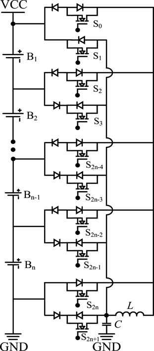
FIGURE 1. Balancing topology structure.
When the cell with the highest power and the cell with the lowest power have different serial numbers, the balancing principle is different due to the moment of the capacitor charging the inductor. For the convenience of explanation, taking the MATLAB/Simulink model of a four-cell series battery pack as an example, the balancing principle in two situations is analyzed. In the simulation model, the cell capacity is 3.2 Ah, the duty cycles of the control signal for charging and discharging are both 50%, the inductance is 100 μH, the capacitance is 1 μF, the switching frequency is 10 kHz, and the forward voltage drop of the diode is 0.4 V.
Suppose that the power of B1 is the highest, B3 is the lowest, and the difference between them is greater than the starting threshold of the balancing circuit. Each switching cycle of the balancing process includes two stages. The current loops of each stage are shown in Figure 2A, and the waveforms of the balancing current and capacitor voltage are shown in Figure 2B.
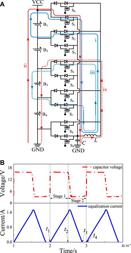
FIGURE 2. The working principle of the power of B1 is the highest and the B3 is the lowest. (A) Balancing current loops. (B) Waveforms of the balancing current and capacitor voltage.
In Stage 1, the inductor current at t1 is zero, and the capacitor voltage is the voltage at the end of the previous cycle. At this moment, MOSFETs S1 and S2 are turned on, and the energy is transferred from B1 to the inductor through loop i. The current flowing through the inductor gradually increases. At the same time, the entire battery pack charges the capacitor through loop ii, and the capacitor voltage quickly changes to the battery pack voltage and remains unchanged until time t2. At t2, MOSFETs S1 and S2 are disconnected, and Stage 1 ends. In Stage 2, MOSFETs S4 and S7 are turned on at moment t2. The inductor charges B3 through loop iii, and the capacitor charges the inductor through loop iv. Because the capacitor voltage cannot change suddenly, the capacitor will continue to charge the inductor after Stage 1, and the inductor current will continue to increase. When the capacitor voltage is equal to the voltage of B3, the inductor current reaches the peak and then begins to decrease. The inductor current drops to zero at t3. Thus, the energy transfer process of one switching cycle is completed. Suppose that the power of B3 is the highest and B1 is the lowest. Each switching cycle of the balancing process also includes two stages. The current loops of each stage are shown in Figure 3A, and the waveforms of the balancing current and capacitor voltage are shown in Figure 3B.
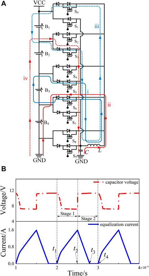
FIGURE 3. The working principle of the power of B3 is the highest, and B1 is the lowest. (A) Balancing current loops. (B) Waveforms of the balancing current and capacitor voltage.
In Stage 1, the inductor current at t1 is zero, and the capacitor voltage is the voltage of the negative pole of B1. At this moment, MOSFETs S5 and S6 are controlled to be turned on, and B3 and the capacitor charge the inductor through loops i and ii, respectively. When the capacitor voltage is equal to the voltage of the positive pole of B4, the capacitor no longer charges the inductor, and the inductor current increases at a slower rate. At t2, the inductor current reaches the peak, disconnects MOSFETs S5 and S6, and ends at Stage 1.
In Stage 2, MOSFETs S0 and S3 are controlled to be turned on at moment t2. The inductor charges B1 through loop iii, and the inductor current gradually decreases. At the same time, B2, B3, and B4 charge the capacitor through loop iv, and the capacitor voltage increases to the voltage of the negative pole of B1 again. The inductor current drops to zero at moment t3. Thus far, the energy transfer process of one switching cycle is completed.
In the aforementioned situations, the inductor must work in discontinuous current mode to avoid inductor hysteresis saturation during the balancing process. In addition, to ensure the reliability of balancing control, there is a dead time after t3, and the next balanced cycle starts at t4. Based on the above description, the characteristics of the new balancing method can be summarized as follows:
1) The energy storage device only requires one inductor and one capacitor. The balancing topology structure is simple.
2) In each balancing stage, only two MOSFETs need to be controlled on or off. In addition, in the charging balancing process of a low-power cell, when the inductor current drops to zero, the low-power cell will not charge the inductor in reverse due to the reverse cutoff effect of the diode. This can reduce the topological requirements on the accuracy of the control signals.
3) The balancing function is perfect, which cannot only achieve a balancing of cells to cells but also achieve a balancing of cells to pack or pack to pack.
To ensure the reliable operation of the balancing process, key parameters, such as switching frequency, duty cycle, inductance, and capacitance, need to be analyzed and calculated. Assuming that Bi has the highest power, MOSFETs S2i-1 and S2i are controlled to charge the inductor, where Bj has the lowest power, and MOSFETs S2j+1 and S2j-2 are controlled to charge Bj, where i, j = 1,2,…, n, and i ≠ j. For convenience, set the voltage of Bn as Vn, the voltage of the capacitor as VC, the diode on-voltage drop as VD, the switching frequency as f, the balancing period as T, the inductance as L, and the capacitance as C. The duty cycle of the inductor charge and discharge process is α and α’. In one balancing cycle, both the high-power cell and capacitor will charge the inductor. Suppose that the charging current of the high-power cell to the inductor is iB and that the charging current of the capacitor to the inductor is iC then the expression of the inductor current iL in an equalization cycle is:
For example, when the serial number i of the high-power cell is smaller than the serial number j of the low-power cell, is analyzed as an example. At the beginning of the first stage, MOSFETs S2i-1 and S2i are turned on, and the Bi forms a circuit with the inductor L. The Bi charges the inductor L and the inductor current rises linearly. The inductor current flows through the two diodes and the time t of the first stage is αT. Thus, the maximum equalization current Imax caused by Bi can be expressed as:
From Eq. 2, the following can be obtained:
At the beginning of the second stage, the S2j-2 and S2j+1 of MOSFET are turned on, and the Bj and the L form a circuit, and the L charges the Bj. At this stage, the inductor current also flows through the two diodes and the inductor current approximately satisfies the ramp function. Write the circuit equation according to Kirchhoff’s voltage law:
If Eq. 4 is substituted in the aforementioned initial conditions, then:
In an equalization cycle, to ensure the equalization control’s reliability and avoid hysteresis saturation, it is necessary to leave a dead time after the end of inductor charging and discharging before starting the next cycle. This leads to:
Then the expression of the inductor current iB in one equalization cycle is:
When t = T,
This leads to the setting standards for the duty cycle α of the first stage, which is:
In addition, combining Eqs 2, 5 in order to reset the inductor within a switching cycle, it is necessary to satisfy the following:
In the first stage, the voltage of the capacitor is:
At the beginning of the second stage, MOSFETs S2j+1 and S2j-2 are turned on. Suppose that after Δt, the capacitor voltage is:
Based on the Kirchhoff’s law for loop iv in Figure 2A, if the number of cells of the battery pack is expanded to n, there is an equation:
Combining the initial conditions, the following can be solved:
Substituting Eq. 12 into Eq. 14, the following can be obtained:
According to the superposition theorem, the inductor current iL in this stage is:
By solving Eq. 10, it can be determined that when t is equal to the value of Eq. 11, the inductor current iL is the largest.
Substituting Eq. 17 into Eqs 14, 16 to obtain the inductive maximum balancing current ILmax:
The discharging time of the inductor is determined by Eq. 19:
When the serial number i of the high-power cell is greater than the serial number j of the low-power cell, the calculation process is similar to what has been mentioned earlier. It is only in the first cycle that the capacitor voltage reaches a high potential, and no energy is released. Starting from the second cycle, the capacitor and the high-power cell charge the inductor together.
After completing the topological function parameter design, the security parameters need to be analyzed. With an increase in the number of cells in the proposed topology, the reverse voltage on the MOSFETs and diode will increase, affecting the topology’s security. For the diode, when B1 is discharging, the diode corresponding to MOSFET S2n+1 will withstand the maximum reverse voltage, or when cell Bn is discharging, the diode corresponding to MOSFET S0 will withstand the maximum reverse voltage. The maximum reverse voltage mentioned earlier is approximately equal to the battery pack voltage. Suppose the reverse breakdown voltage of the diode is VDBR, and the drain-source breakdown voltage of the MOSFET is VMBR. The diode and MOSFET selection process must ensure the following:
Finally, the efficiency of the balancing topology needs to be studied. The MOSFETs used in the balancing experiment in this article are STMicroelectronics IRF630, and its on-drain-source resistance RDS is 0.3 Ω. Its switching loss and cutoff loss are very small compared to the on-state loss and are therefore negligible. The Schottky diode used is STMicroelectronics 1N5819. The diode voltage drop VD is 0.4 V under the average forward current of a 1 A conduction state, and its switching loss and cutoff loss are negligible. The capacitance is on the order of μF, and the power consumption can also be ignored. Based on this, for the convenience of calculation, an approximate study of the balancing efficiency is conducted based on the energy change during the charging and discharging process of the inductor.
Assume that the energy released by the high-power cell Bi in one switching cycle is Wi. Wi is then the sum of the energy stored in the inductor and the energy loss in the balancing path. This can be expressed by Eq. 21:
Assume that the energy absorbed by the low-power cell Bj is Wj. Then, Wj is the difference between the energy released by the inductor and the energy loss from the balancing path. It can be expressed by Eq. 23:
Assume that the balancing efficiency is η. According to the change in energy before and after balancing in one switching cycle, η can be expressed as:
It can be seen from Eq. 25 that the factors that affect the balancing efficiency include the product of the inductance and the switching frequency, the voltage drop of the diode, and the duty cycle of the MOSFETs, and the voltage of the balanced object. In the experiment, first, the maximum balancing current needs to be set. Second, set the inductance, capacitance, switching frequency, and duty cycle are set based on the maximum balancing current. The fourth part of the article will determine the specific experimental parameters through a comparative analysis based on the simulation models.
In the balancing process, the balanced threshold is set first, and then the balanced object is determined. Suppose the highest SOC in the battery pack is Smax, the lowest SOC is Smin, and the balanced threshold is Sref. If the difference between Smax and Smin is greater than Sref, then balancing is started by turning on or turning off the corresponding MOSFETs. Otherwise, the balancing circuit does not work. In addition, if the number of cells with the highest or lowest SOC is not 1, the cells with the closest sequence numbers will be equalized first. The flow chart of the adaptive balancing control is shown in Figure 4.
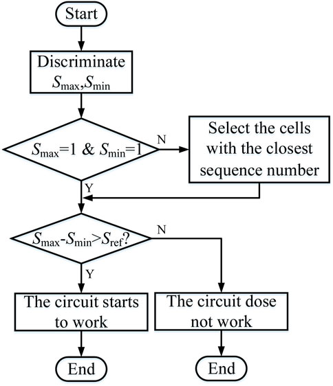
FIGURE 4. Flow chart of the adaptive balancing control strategy.
This section mainly includes an analysis of the balancing speed and efficiency of the new balancing method under different conditions, a comparative analysis of the balancing speed and efficiency between the new balancing method and the similar LC energy storage balancing method, a balancing topology cost analysis, and a balancing control mode analysis.
Taking the balancing of the four-cell battery pack in the idle state as an example, the balancing speed and efficiency are analyzed by building the simulation models in MATALB/Simulink. The cell parameters are shown in Table 1.
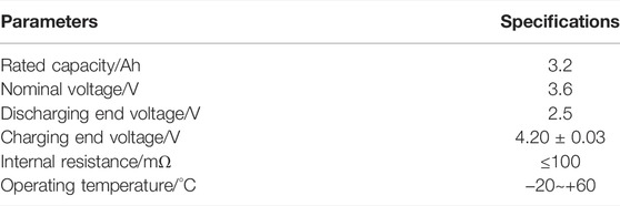
TABLE 1. Battery parameters.
It can be seen from the parameter design process in Section 3 that the main factors affecting the balancing speed and efficiency include such parameters as the switching frequency, duty cycle, inductance, and capacitance. First, this section uses cell-to-cell balancing as an example to verify the balancing speed and efficiency. The principle of duty cycle design is to make the inductor in a critical saturation state during each switching cycle. Second, in conjunction with the parameter design process in Section 3, the performance of the balancing speed and efficiency under different switching frequencies, inductances, and capacitances is studied through simulation models. To be consistent with the actual standard value of inductance and capacitance, nine groups of different values are set for the balancing speed and efficiency analysis. The balancing efficiency is calculated based on the change in the capacity of the battery pack before and after balancing. The simulation model parameters are shown in Table 2; Figure 5 shows the simulation results.
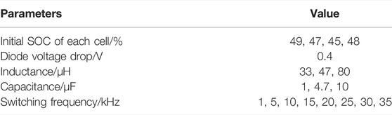
TABLE 2. Simulation parameters of the balancing model.
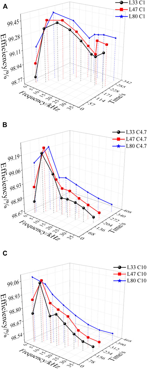
FIGURE 5. Simulation results of the balancing efficiency and time. (A) Balancing efficiency and time for a 1 μF capacitor. (B) Balancing efficiency and time for a 4.7 μF capacitor. (C) Balancing efficiency and time for a 10 μF capacitor.
It can be seen from Figure 5 that for the balancing efficiency, when the capacitance is 1 μF, compared with the other two values, the balancing efficiency is the highest. This is because the smaller the capacitance, the smaller the loss. When the switching frequency is small, large, or approximately equal to the LC resonance frequency, the balancing efficiency is reduced. The reason is that when the switching frequency is small or approximately equal to the resonance frequency of the LC series circuit, the balancing current is large, which in turn leads to large losses in the energy storage device and a lower balancing efficiency. When the switching frequency is large, the balancing current is small, but the switching loss increases, and the balancing efficiency decreases.
It should be noted that when the capacitance is 10 μF and the inductance is 47 and 80 μH, if the switching frequency is greater than the resonance frequency, then the balancing efficiency does not increase. The reason is that when the switching frequency is greater than the resonance frequency, the switching loss has a greater impact on the balancing efficiency than the resonance frequency. In addition, when the capacitance is 10 μF and the inductance is 80 μH, when the switching frequency is low, due to the large capacitance and inductance, under the same conditions the balancing current is still small, resulting in high efficiency.
For the balancing speed under the same conditions, when the inductance is 33 μH, the balancing speed is the fastest. This is because the smaller the inductance, the faster the inductor current increases or decreases. When the switching frequency is small, or approximately equal to the series resonance frequency of the LC circuit, the balancing current is large, and the balancing speed is fast. When the switching frequency is large, the balancing current is small, and the balancing speed decreases. For the balancing current, the larger is not better; the greater the balancing current, the greater the impact it has on the battery’s charge or discharge efficiency and the aging process. In summary, when the switching frequency is 10 K, the overall balancing efficiency is high, and the balancing speed is moderate. In the experimental part of this article, the final selection of the control signal switching frequency is 10 kHz, and the inductance and capacitance are 33 μH and 1 μF, respectively.
For a comparative analysis, the balancing methods in Shang et al. (2020b) and Yu et al. (2020), which are also LC energy storage, are used as the comparison object, and the simulation models are established in MATLAB/Simulink with a battery pack composed of four cells. The topologies in Shang et al. (2020b) and Yu et al. (2020) are based on LC series resonance for balancing. Before and after balancing, the voltage difference of the balancing object will affect both the balancing speed and efficiency. This section compares the speed and efficiency of different initial difference conditions and different balancing modes (three cells to one, two cells to one, and one cell to one). The basis of each model parameter setting is to make the balancing current as large as possible, so the balancing effect is as good as possible. The simulation parameters are shown in Table 3.
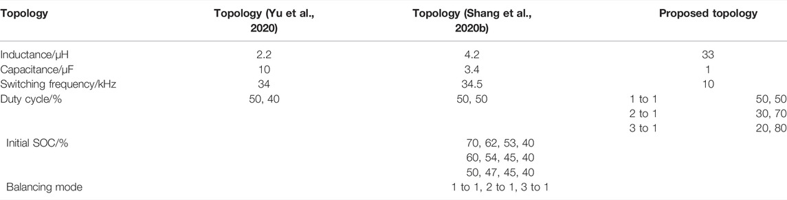
TABLE 3. Key simulation parameters of the balancing model.
The balancing speed is defined as the energy transferred per unit of time, and the expression is shown in Eq. 26. The balancing efficiency is defined as the ratio of the sum of the SOC of the battery pack before and after balancing (Guo et al., 2021b), and the expression is shown in Eq. 27. The simulation time is set to 50 s, and the results are shown in Figures 6, 7.
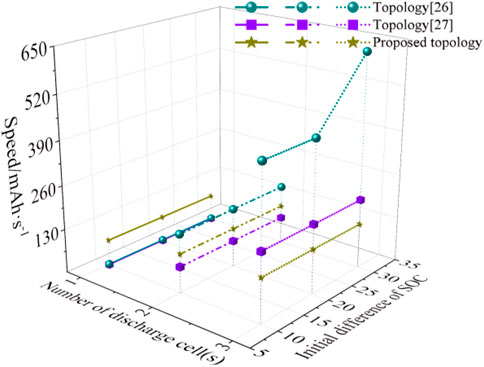
FIGURE 6. Balancing speed comparison.

FIGURE 7. Balancing efficiency comparison.
It can be seen from Figure 6 that when one cell is balanced by one cell, the new topology balancing speed is the fastest, while when one cell is balanced by multiple cells at the same time, the topological balancing speed of reference (Yu et al., 2020) is faster. This shows that when the voltage difference of the balanced object is not large, then the new topology balancing speed is the fastest, and when the voltage difference of the balanced object is large, the balancing speed of references (Shang et al., 2020b; Yu et al., 2020) is faster. The initial SOC difference has almost no effect on the new topology and the reference (Shang et al., 2020b) topology. When one cell is balanced by three cells, as the initial SOC difference increases, the balancing speed of reference (Yu et al., 2020) also tends to increase. In general, when one cell is balanced by one cell, the new topology has a relatively obvious speed advantage. When one cell is balanced by multiple cells, the new topology no longer has a speed advantage.
It can be seen from Figure 7 that when one cell is balanced by one cell, the efficiency of the new topology is lower, while when one cell is balanced by multiple cells, the topological balancing efficiency of references (Shang et al., 2020b; Yu et al., 2020) decreases significantly, while the new topology shows almost no decrease. When one cell is balanced by three cells, the topology in Yu et al. (2020) increases with an increase of the initial SOC difference, and the balancing efficiency first increases and then decreases.
It can be seen from Figures 6, 7 that for the new topology, when the balancing mode changes, although the balancing speed and efficiency also change, the change is not obvious. The initial SOC difference has almost no effect on the balancing speed or efficiency. For the topologies in Shang et al. (2020b) and Yu et al. (2020), as the balancing mode changes, the balancing speed increases while the efficiency decreases. This is because as the balancing speed increases, the balancing current increases, which leads to an increase in the loss of the energy storage device, and then the balancing efficiency decreases. The new topology balancing mode changes, the balancing speed increases, and the balancing efficiency drops by less than the reference topologies (Shang et al., 2020b; Yu et al., 2020). The reason is that achieving the same balancing effect does not require resonance, the balancing current is small, and the loss of the energy storage device is small.
In summary, compared with the current mainstream LC energy storage topologies, when one cell is balanced by one cell, the balancing speed is faster, and when one cell is balanced by multiple cells, the balancing efficiency is high.
Take the 18,650 ternary lithium battery pack composed of 4 cells, 8 cells, and 12 cells as examples. The unit price of each device is determined based on the references (Shang et al., 2019; Shang et al., 2020b), and the new topology is compared with the current mainstream topologies. The specific analysis results are shown in Figure 8. Component cost per unit ($): MOSFET (0.2), Diode (0.03), Winding (0.2), Transformer Core (0.5), Inductor (0.25), Capacitor (0.25).
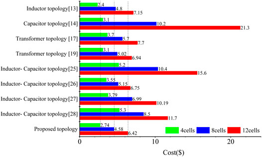
FIGURE 8. Analysis of the topological cost.
It can be seen from Figure 8 that the cost of the new topology has decreased compared with the current mainstream topologies. As the number of cells increases, the cost advantage becomes increasingly obvious. The topology proposed by Ding et al. (2020) uses the inductor for energy transfers. When the number of cells is small, the cost is lower, while as the number of cells increases, the number of required inductors also increases, which increases the cost and volume. The number of switch tubes used, proposed by Shang et al. (2018) is small, but as the number of cells increases, the number of capacitors increases significantly, which in turn leads to an increase in the topological cost. The topologies in Liu et al. (2021a) and Nazi and Babaei (2021) are based on the transformer to transfer energy, where the cost is low and the change in the number of cells does not cause a significant increase in cost. However, each module or cell needs to be equipped with a winding, which is not conducive to the reduction of the balancing system volume. The topologies in Shang et al. (2020b), Yu et al. (2020), Liu et al. (2021b), and Raeber et al. (2021) are based on LC energy storage to transfer energy. In the topology proposed by Liu et al. (2021b) each cell must be equipped with an LC series circuit, which greatly increases the volume and cost of the system. The energy storage device in Raeber et al. (2021) requires one inductor and two capacitors, and the references (Shang et al., 2020b; Yu et al., 2020) only need one inductor and one capacitor. Although the topological switch array in Shang et al. (2020b), Yu et al. (2020), and Raeber et al. (2021) does not need diodes, the number of switch tubes is large, which in turn leads to a higher cost. Compared with the current mainstream topologies, this new topology requires an inductor and a capacitor, and each cell needs to be equipped with two switching tubes, which is beneficial for reducing the balancing system volume. Although the topology requires a large number of diodes, the volume and cost of diodes are much smaller than those of switching tubes, which is beneficial for reducing system cost and volume. In summary, the proposed topology has a significant advantage in terms of the cost and volume of the balancing system.
Simple switch control is another significant characteristic of the new topology. The new topology switch array unit and the switch array unit are based on the common topologies of LC energy storage (Shang et al., 2020b; Yu et al., 2020; Liu et al., 2021b; Raeber et al., 2021) are shown in Figure 9.
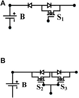
FIGURE 9. Switch array unit. (A) New topology switch array unit. (B) Common topology switch array unit.
In Figure 9A, S1 is turned on and cell B is charged. When the charging current drops to zero, even if the drive signal of S1 still exists, cell B will not be discharged through S1, because the diode is reversely cut off. In Figure 9B, S2 and S3 share a driving signal. S2 and S3 are turned on, and cell B is charged. When the charging current drops to zero, S2 and S3 must be turned off immediately otherwise cell B will be discharged through S2 and S3, which will affect the balancing effect and even lead to failure of the balancing. If S2 and S3 are turned off early, then the energy storage device may be saturated. In addition, when the balancing object changes, the duty cycle of the switch control signal in Figure 9B needs to be recalculated to ensure smooth switching of the cell charge and discharge circuit, which puts forward higher requirements in terms of the computing power of the controller. In summary, the fault tolerance of the new topology control signal duty cycle is significantly higher than the current common topologies, and the applicability to all cells in the pack is better.
Obtaining an accurate SOC of each cell appropriately is the premise of taking SOC as the balancing index. The existing SOC acquisition methods include the ampere-hour (Ah) integration method, the open-circuit voltage (OCV) method, the mathematical model method, etc. (Shen et al., 2019). Among them, the Ah integration method has the advantage of a simple measurement. In this article, the Ah integration is used to calculate the SOC of each cell. The key to using Ah integration is to collect an accurate balancing current. Considering that the balancing current in the hardware experiment is relatively small, the current probe cannot obtain an accurate current value, so in this article, the current sampling circuit is used to collect the balancing current of each cell. The specific steps are as follows: first, the sampling resistance is connected in series with the positive pole of each cell. Second, a voltage amplifier circuit designed based on the high-precision integrated operational amplifiers LM124 and OP07 is used to collect the voltage across the sampling resistor. Then, the output value of the voltage sampling circuit is divided by the sampling resistor to obtain the current value on each cell. Finally, the current value is integrated to obtain the change in the SOC and then combined with the initial SOC to obtain the actual SOC during the balancing process. The four-channel current sampling circuit based on LM124 and OP07 is shown in Figure 10.
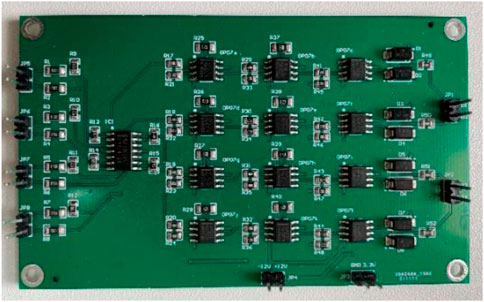
FIGURE 10. The four-channel current sampling circuit.
To verify the effectiveness of the new balancing method, a four-cell series battery pack balancing experiment platform, as shown in Figure 11, was built. The single cell is the 18650 ternary lithium battery produced by Sony Corporation of Japan, with a nominal voltage of 3.7 V and a rated capacity of 3.2 Ah.
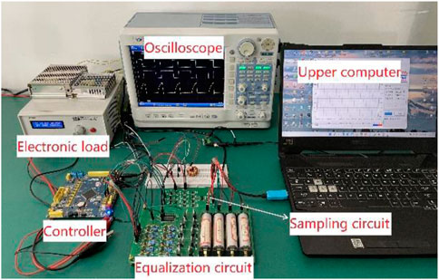
FIGURE 11. Balancing experimental platform.
Based on the parameter design of Section 3 and the simulation analysis of Section 5, the balancing experiment parameters shown in Table 4 are designed. Among them, PWM1 and PWM2 are the control signals of the first stage and the second stage of each switching cycle.
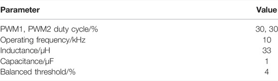
TABLE 4. Balancing experiment parameters.
Set B2 SOC to be the highest and B3 SOC to be the lowest. The waveform of the inductor current in the five switching cycles and the waveforms of the cell voltage change over two switching cycles are shown in Figure 12.
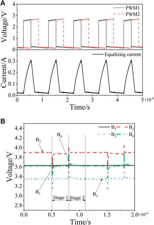
FIGURE 12. The experimental waveforms where the B2 SOC is the highest and the B3 SOC is the lowest. (A) PWM1, PWM2, and inductor current waveforms. (B) Voltage waveforms of each cell.
Figure 12A shows that in the first stage of each switching cycle, the current through the inductor is zero at the initial moment. At this moment, MOSFETs S3 and S4 are turned on, B2 starts to charge the inductor, B2, B3, and B4 charge the capacitor, and the inductor current gradually increases. When the inductor current gradually increases to the set value, MOSFETs S3 and S4 are disconnected, and MOSFETs S4 and S7 are simultaneously turned on. The inductor starts to charge B3, and the capacitor charges the inductor. The inductor current first rises for a short time, and then gradually decreases to zero. It can be seen from Figure 12B that in the first stage, since B2 charges the inductor and B2, B3, and B4 charge the capacitor, the voltage of each cell has a certain drop. After the charging is completed, due to the polarization effect, they rise again. In the second stage, the inductor charges B3, and the voltage of B3 rises. After the inductor current drops to zero, the voltage of B3 drops again due to the polarization effect.
Set the B4 SOC to be the highest and the B2 SOC to be the lowest. The waveform of the inductor current in five switching cycles and the waveforms of the cell voltage change in two switching cycles are shown in Figure 13.
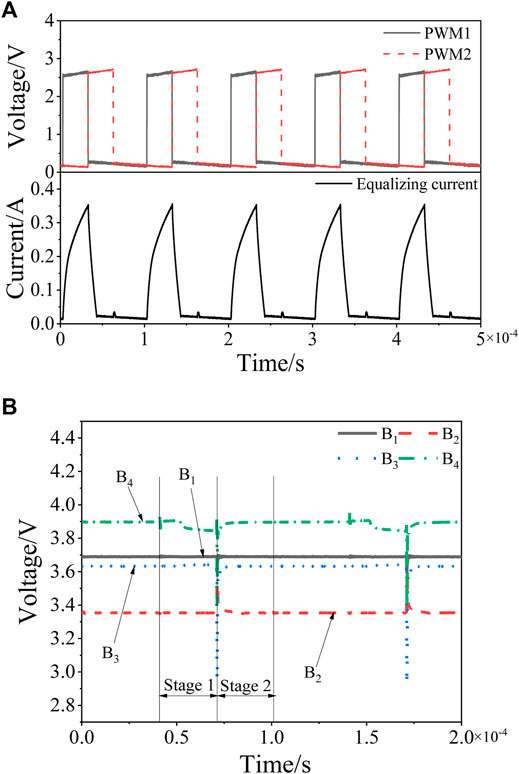
FIGURE 13. The experimental waveforms where the B4 SOC is the highest and the B2 SOC is the lowest. (A) PWM1, PWM2, and inductor current waveforms. (B) Voltage waveforms of each cell.
Figure 13A shows that in the first stage of each switching cycle, the current through the inductor is zero at the initial moment. At this moment, MOSFETs S7 and S8 are turned on, and B4 and the capacitor start to charge the inductor. After the capacitor power is released, only B4 continues to charge the inductor, and the inductor current rises faster at first and then slower. When the inductor current gradually increases to the set value, MOSFETs S7 and S8 are disconnected, and MOSFETs S2 and S5 are simultaneously turned on. The inductor starts to charge B2, and B3, and B4 charge the capacitor. The inductor current gradually decreases to zero. It can be seen from Figure 13B that in the first stage, since B4 charges the inductor, the voltage of B4 has a certain drop. After charging is completed, due to the polarization effect it rises again. In the second stage, the voltage of B2 rises; after the inductor current drops to zero, it drops again due to the polarization effect. At the same time, B3 and B4 charge the capacitor, and the voltages of B3 and B4 decrease. After the inductor current drops to zero, the voltages of B3 and B4 rise again due to the polarization effect.
To verify the overall balancing effect of the new method, the following three sets of balancing experiments are designed. Namely, the battery pack charging (0.7A) balanced experiment, the discharging (0.7A) balanced experiment, and the dynamic balanced experiment. The dynamic balancing experiment was first charged with a 0.7 A current for 30 min, then left for 30 min, and finally discharged with a 0.7 A current for 15 min. The SOC change curve of each cell during the balancing process is shown in Figure 14, and the change in the SOC of each cell before and after equalization balancing is shown in Figure 15.
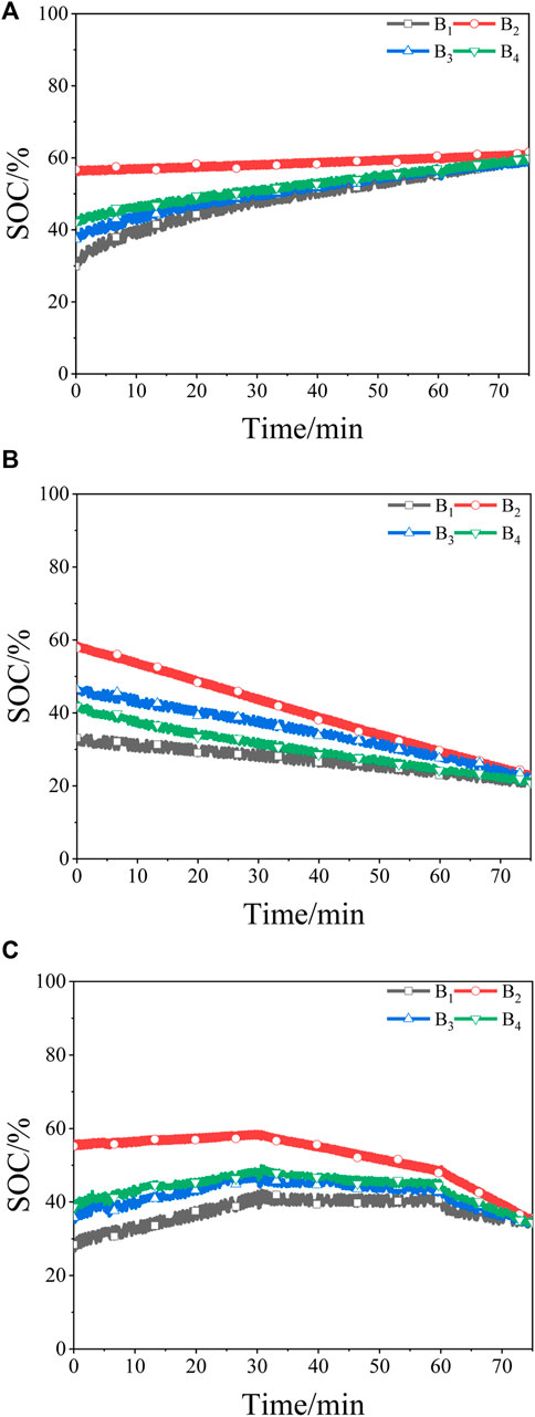
FIGURE 14. Battery pack balancing experiment waveforms. (A) Equalization of the battery pack charging process. (B) Equalization of the battery pack discharging process. (C) Dynamic equalization.
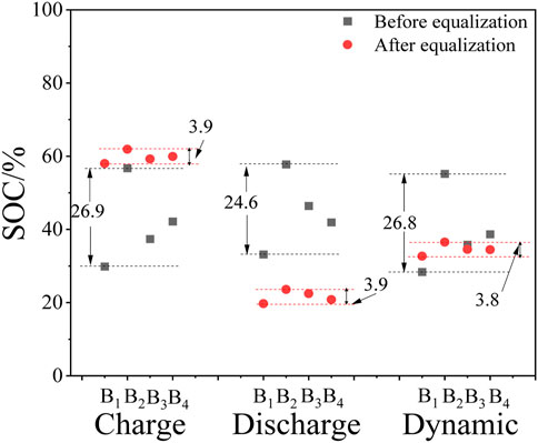
FIGURE 15. SOC change before and after equalization.
It can be seen from Figure 15 that at the initial moment, the SOC inconsistency of the cells satisfies the start-up condition of the balancing circuit, and the balancing circuit starts to work. At the end of balancing, the SOC difference between the individual cells is less than 4%, which meets the stop condition of the balancing circuit. Figures 14, 15 show that the new balancing method has a good equalization effect on the charging/discharging process and the state of shelving, and can significantly improve the consistency of the series battery pack.
To improve the SOC consistency of the series battery pack, a new balancing method based on LC energy storage was proposed, which has the advantages of a simple structure, simple control, and low cost. First, the working principle, parameter design, and control strategy were analyzed in detail. Second, through a comparison of simulation models and topology structure, the characteristics of the new balancing method in terms of a balanced speed, efficiency, and significant topology cost advantages were proven. Finally, a four-cell series battery pack balanced experimental platform was built to verify the overall balanced effect of the new method under battery pack charging, discharging, and dynamic conditions. The SOC difference of each cell can be controlled to within 4%. In the future, the SOC estimation accuracy can be improved to further improve the balancing accuracy.
The original contributions presented in the study are included in the article/Supplementary Material; further inquiries can be directed to the corresponding author.
Conceptualization, XX and CX; methodology, XX; software, XG; validation, CX, QW, and XG; formal analysis, QW; investigation, XG; resources, XX; data curation, CX; writing—original draft preparation, XX; writing—review and editing, CX and XG; visualization, WQ; supervision, XG; project administration, YZ and WQ.
This work was supported in part by the National Natural Science Foundation of China, under Grant 52177039, and in part by the Fundamental Research Funds for the Universities of Henan Province, under Grant NSFRF210332.
The authors declare that the research was conducted in the absence of any commercial or financial relationships that could be construed as a potential conflict of interest.
All claims expressed in this article are solely those of the authors and do not necessarily represent those of their affiliated organizations, or those of the publisher, the editors and the reviewers. Any product that may be evaluated in this article, or claim that may be made by its manufacturer, is not guaranteed or endorsed by the publisher.
XX would like to express my deepest gratitude to WQ, who has provided me with valuable guidance at every stage of writing this article. I would also like to thank the reviewers for dedicating the time to review my article despite their busy schedules.
The Supplementary Material for this article can be found online at: https://www.frontiersin.org/articles/10.3389/fenrg.2022.901811/full#supplementary-material
Cao, Y., and Abu Qahouq, J. A. (2021). Hierarchical SOC Balancing Controller for Battery Energy Storage System. IEEE Trans. Ind. Electron. 68 (10), 9386–9397. doi:10.1109/TIE.2020.3021608
Chen, Y., Liu, X., Shen, T., Cheng, L., Wang, X., Yang, R., et al. (2021). An Any-Cell(s)-To-Cell(s) Equalization Method with a Single Magnetic Component for Lithium-Ion Battery Pack. J. Energy Storage 33, 1–15. doi:10.1016/j.est.2020.102071
Conway, T. (2021). An Isolated Active Balancing and Monitoring System for Lithium Ion Battery Stacks Utilizing a Single Transformer Per Cell. IEEE Trans. Power Electron. 36 (4), 3727–3734. doi:10.1109/TPEL.2020.3024904
Ding, X., Zhang, D., Cheng, J., Wang, B., Chai, Y., Zhao, Z., et al. (2020). A Novel Active Equalization Topology for Series-Connected Lithium-Ion Battery Packs. IEEE Trans. Ind. Appl. 56 (6), 6892–6903. doi:10.1109/TIA.2020.3015820
Ghaeminezhad, N., Ouyang, Q., Hu, X., Xu, G., and Wang, Z. (2021). Active Cell Equalization Topologies Analysis for Battery Packs: A Systematic Review. IEEE Trans. Power Electron. 36 (8), 9119–9135. doi:10.1109/TPEL.2021.3052163
Guo, X., Geng, J., Liu, Z., Xu, X., and Cao, W. (2021). A Flyback Converter-Based Hybrid Balancing Method for Series-Connected Battery Pack in Electric Vehicles. IEEE Trans. Veh. Technol. 70 (7), 6626–6635. doi:10.1109/TVT.2021.3087320
Guo, X., Liu, Z., Xu, X., Geng, J., and Kang, L. (2021). Integrated Balancing Method for Series‐parallel Battery Packs Based on LC Energy Storage Integrated Balancing Based on LC. IET Electr. Power Appl. 15 (5), 579–592. doi:10.1049/elp2.12047
Lee, K.-M., Chung, Y.-C., Sung, C.-H., and Kang, B. (2015). Active Cell Balancing of Li-Ion Batteries Using $LC$ Series Resonant Circuit. IEEE Trans. Ind. Electron. 62 (9), 5491–5501. doi:10.1109/TIE.2015.2408573
Liu, L., Mai, R., Xu, B., Sun, W., Zhou, W., and He, Z. (2021). Design of Parallel Resonant Switched-Capacitor Equalizer for Series-Connected Battery Strings. IEEE Trans. Power Electron. 36 (8), 9160–9169. doi:10.1109/TPEL.2021.3052780
Liu, L., Xu, B., Yan, Z., Zhou, W., Li, Y., Mai, R., et al. (2021). A Low-Cost Multiwinding Transformer Balancing Topology for Retired Series-Connected Battery String. IEEE Trans. Power Electron. 36 (5), 4931–4936. doi:10.1109/TPEL.2020.3031904
Nazi, H., and Babaei, E. (2021). A Modularized Bidirectional Charge Equalizer for Series-Connected Cell Strings. IEEE Trans. Ind. Electron. 68 (8), 6739–6749. doi:10.1109/TIE.2020.3003661
Ouyang, Q., Chen, J., Zheng, J., and Hong, Y. (2018). SOC Estimation-Based Quasi-Sliding Mode Control for Cell Balancing in Lithium-Ion Battery Packs. IEEE Trans. Ind. Electron. 65 (4), 3427–3436. doi:10.1109/TIE.2017.2750629
Raeber, M., Heinzelmann, A., and Abdeslam, D. O. (2021). Analysis of an Active Charge Balancing Method Based on a Single Nonisolated DC/DC Converter. IEEE Trans. Ind. Electron. 68 (3), 2257–2265. doi:10.1109/TIE.2020.2972449
Shang, Y. L., Cui, N. X., and Zhang, C. H. (2019). An Optimized Any-Cell-To-Any-Cell Equalizer Based on Coupled Half-Bridge Converters for Series-Connected Battery Strings. IEEE Trans. Power Electron 34 (9), 8834–8841. doi:10.1109/TPEL.2018.2888514
Shang, Y., Xia, B., Lu, F., Zhang, C., Cui, N., and Mi, C. C. (2017). A Switched-Coupling-Capacitor Equalizer for Series-Connected Battery Strings. IEEE Trans. Power Electron. 32 (10), 7694–7706. doi:10.1109/TPEL.2016.2638318
Shang, Y., Zhang, C., Cui, N., and Mi, C. (2018). A Delta-Structured Switched-Capacitor Equalizer for Series-Connected Battery Strings. IEEE Trans. Power Electron. 34 (1), 1. doi:10.1109/TPEL.2018.2826010
Shang, Y., Zhang, Q., Cui, N., Duan, B., Zhou, Z., and Zhang, C. (2020). Multicell-to-Multicell Equalizers Based on Matrix and Half-Bridge LC Converters for Series-Connected Battery Strings. IEEE J. Emerg. Sel. Top. Power Electron. 8 (2), 1755–1766. doi:10.1109/JESTPE.2019.2893167
Shang, Y., Zhao, S., Fu, Y., Han, B., Hu, P., and Mi, C. C. (2020). A Lithium-Ion Battery Balancing Circuit Based on Synchronous Rectification. IEEE Trans. Power Electron. 35 (2), 1637–1648. doi:10.1109/TPEL.2019.2917390
Shen, J.-N., Shen, J.-J., He, Y.-J., and Ma, Z.-F. (2019). Accurate State of Charge Estimation with Model Mismatch for Li-Ion Batteries: A Joint Moving Horizon Estimation Approach. IEEE Trans. Power Electron. 34 (5), 4329–4342. doi:10.1109/TPEL.2018.2861730
Shi, G., Han, H., Sun, Y., Liu, Z., Zheng, M., and Hou, X. (2021). A Decentralized SOC Balancing Method for Cascaded-type Energy Storage Systems. IEEE Trans. Ind. Electron. 68 (3), 2321–2333. doi:10.1109/TIE.2020.2973889
Tang, X., Zou, C., Wik, T., Yao, K., Xia, Y., Wang, Y., et al. (2020). Run-to-Run Control for Active Balancing of Lithium Iron Phosphate Battery Packs. IEEE Trans. Power Electron. 35 (2), 1499–1512. doi:10.1109/TPEL.2019.2919709
Tavakoli, A., Khajehoddin, S. A., and Salmon, J. (2020). A Modular Battery Voltage-Balancing System Using a Series-Connected Topology. IEEE Trans. Power Electron. 35 (6), 5952–5964. doi:10.1109/TPEL.2019.2950409
Turksoy, A., Teke, A., and Alkaya, A. (2020). A Comprehensive Overview of the Dc-Dc Converter-Based Battery Charge Balancing Methods in Electric Vehicles. Renew. Sustain. Energy Rev. 133, 1–20. doi:10.1016/j.rser.2020.110274
Uno, M., and Kukita, A. (2019). String-to-Battery Voltage Equalizer Based on a Half-Bridge Converter with Multistacked Current Doublers for Series-Connected Batteries. IEEE Trans. Power Electron. 34 (2), 1286–1298. doi:10.1109/TPEL.2018.2829664
Wang, Y., Liu, D., Shen, Y., Tang, Y., Chen, Y., and Zhang, J. (2022). Adaptive Balancing Control of Cell Voltage in the Charging/Discharging Mode for Battery Energy Storage Systems. Front. Energy Res. 10 (794191), 1–9. doi:10.3389/fenrg.2022.794191
Wei, Z., Peng, F., and Wang, H. (2021). An LCC Based String-To-Cell Battery Equalizer with Simplified Constant Current Control. IEEE Trans. Power Electron. 37 (2), 1. doi:10.1109/TPEL.2021.3102627
Xia, Z., and Abu Qahouq, J. A. (2021). State-of-Charge Balancing of Lithium-Ion Batteries with State-Of-Health Awareness Capability. IEEE Trans. Ind. Appl. 57 (1), 673–684. doi:10.1109/TIA.2020.3029755
Xu, B., Tu, H., Du, Y., Yu, H., Liang, H., and Lukic, S. (2021). A Distributed Control Architecture for Cascaded H-Bridge Converter with Integrated Battery Energy Storage. IEEE Trans. Ind. Appl. 57 (1), 845–856. doi:10.1109/TIA.2020.3039430
Ye, M., Song, X., Xiong, R., and Sun, F. (2019). A Novel Dynamic Performance Analysis and Evaluation Model of Series-Parallel Connected Battery Pack for Electric Vehicles. IEEE Access 7, 14256–14265. doi:10.1109/ACCESS.2019.2892394
Ye, Y., and Cheng, K. W. E. (2018). Analysis and Design of Zero-Current Switching Switched-Capacitor Cell Balancing Circuit for Series-Connected Battery/Supercapacitor. IEEE Trans. Veh. Technol. 67 (2), 948–955. doi:10.1109/TVT.2017.2749238
Ye, Y., Cheng, K. W. E., Fong, Y. C., Xue, X., and Lin, J. (2017). Topology, Modeling, and Design of Switched-Capacitor-Based Cell Balancing Systems and Their Balancing Exploration. IEEE Trans. Power Electron. 32 (6), 4444–4454. doi:10.1109/TPEL.2016.2584925
Yu, Y., Saasaa, R., Khan, A. A., and Eberle, W. (2020). A Series Resonant Energy Storage Cell Voltage Balancing Circuit. IEEE J. Emerg. Sel. Top. Power Electron. 8 (3), 3151–3161. doi:10.1109/JESTPE.2019.2914706
Zhang, C., Jiang, Y., Jiang, J., Cheng, G., Diao, W., and Zhang, W. (2017). Study on Battery Pack Consistency Evolutions and Equilibrium Diagnosis for Serial- Connected Lithium-Ion Batteries. Appl. Energy 207, 510–519. doi:10.1016/j.apenergy.2017.05.176
Keywords: battery pack, inductor, capacitor, active equalization, simulation models, experimental platform
Citation: Xu X, Xing C, Wu Q, Qian W, Zhao Y and Guo X (2022) An Active State of Charge Balancing Method With LC Energy Storage for Series Battery Pack. Front. Energy Res. 10:901811. doi: 10.3389/fenrg.2022.901811
Received: 22 March 2022; Accepted: 21 April 2022;
Published: 25 May 2022.
Edited by:
Manickam Minakshi, Murdoch University, AustraliaReviewed by:
Sorout Shalini, University of Michigan, United StatesCopyright © 2022 Xu, Xing, Wu, Qian, Zhao and Guo. This is an open-access article distributed under the terms of the Creative Commons Attribution License (CC BY). The use, distribution or reproduction in other forums is permitted, provided the original author(s) and the copyright owner(s) are credited and that the original publication in this journal is cited, in accordance with accepted academic practice. No use, distribution or reproduction is permitted which does not comply with these terms.
*Correspondence: Xiangwei Guo, Z3h3QGhwdS5lZHUuY24=
Disclaimer: All claims expressed in this article are solely those of the authors and do not necessarily represent those of their affiliated organizations, or those of the publisher, the editors and the reviewers. Any product that may be evaluated in this article or claim that may be made by its manufacturer is not guaranteed or endorsed by the publisher.
Research integrity at Frontiers
Learn more about the work of our research integrity team to safeguard the quality of each article we publish.