 Jun Yin
 Haoyu Nie
94% of researchers rate our articles as excellent or good
Learn more about the work of our research integrity team to safeguard the quality of each article we publish.
Find out more
BRIEF RESEARCH REPORT article
Front. Energy Res., 09 May 2022
Sec. Smart Grids
Volume 10 - 2022 | https://doi.org/10.3389/fenrg.2022.900120
This article is part of the Research TopicAdvanced Data-Driven Methods and Applications for Smart Power and Energy SystemsView all 31 articles
With the continuous increase in the scale of photovoltaic grid connection, the impact of the safe and stable operation of photovoltaic power generation systems on the grid cannot be ignored. When a short-term failure of the power grid occurs, the large-scale disconnection of the unit will seriously affect the stability of the grid voltage and frequency. Therefore, this paper proposes a non-linear control method for photovoltaic power generation low voltage ride through (LVRT) based on adaptive maximum power tracking. This method adaptively adjusts the power tracking trajectory through the feedforward control of the voltage drop amplitude. Cooperating with the nonlinear control of the grid-connected inverter, this method can quickly and effectively control the power output of photovoltaic cells on the basis of providing appropriate reactive power support, so as to realize the rapid response of grid system. Through the simulation in PSCAD, it is verified that the control method described in this article can well realize the LVRT in different amplitudes of the photovoltaic system, especially when zero voltage drops occur.
Nowadays, with the continuous increase in the scale of photovoltaic grid connection, the impact of the safe and stable operation of photovoltaic power generation systems on the grid cannot be ignored. When a short-term fault occurs in the power grid, the large-scale disconnection of the unit will seriously affect the stability of the grid voltage and frequency, threaten the safety and stable operation of the power grid, and may even collapse the local power grid and cause a large area of power supply interruption (Telukunta_and Pradhan_JAgrawal, 2018; Ma and Liu, 2018; Li et al., 2020; Li et al., 2022a). Therefore, the power grid requires photovoltaic generator sets should have a certain LVRT capability like traditional conventional generators. China’s national standard “Technical Regulations for Connecting Photovoltaic Power Stations to Power Systems” points out the LVRT requirements that photovoltaic power stations should meet: when the grid-connected point voltage drops to 0, the photovoltaic power station should be able to operate continuously for 0.15s without going off the grid.
In the existing research on LVRT strategies, most of them are to achieve LVRT by changing the system topology or adding additional equipment. The parallel unloading resistance method at the DC bus bar proposed in the literature (Bighash et al., 2018; Sajadian and Ahmadi, 2018; Zhang et al., 2020), is one of the most commonly used methods. During a fault, the unloading resistor consumes the excess energy from the photovoltaic cells to maintain the power balance on both sides of the inverter, limit the increase of the DC side voltage and the overcurrent of the AC side grid-connected current, so as to meet the requirements of LVRT. However, this method does not consider the supporting effect of the inverter reactive current on the voltage recovery. And the addition of parallel unloading resistors not only increases the cost, but the large amount of heat generated will also affect the safety and stability of the grid-connected system.
There are also documents that have proposed a method of changing the control strategy without adding additional equipment to achieve LVRT during a fault. Literature (Benali et al., 2018; Huka et al., 2018; Elazab et al., 2020), proposed a LVRT strategy that switches the constant power double closed-loop control of the inverter under normal conditions to the single closed-loop control of constant grid-connected current under fault conditions, by detecting the voltage drop signal of the grid. Although this can ensure that the grid-connected current does not flow, due to the lack of external loop control of the DC bus voltage in the fault state, this method cannot guarantee the stability of the DC bus voltage. And the DC bus will have overvoltage. Moreover, none of the above methods has verified the feasibility of the strategy under different environmental conditions and different voltage drop amplitudes, especially the operation of the system in the most serious situation of zero voltage crossing.
In addition, in the LVRT process, the control of the grid-connected inverter also plays a key role. In the existing control methods of grid-connected inverters (Fan et al., 2017; Li et al., 2018; Nasiri et al., 2021; Li et al., 2022b), traditional control methods such as voltage control, current control, and voltage and current double closed-loop control can basically realize the stable and controllable bus voltage or current, but there are also difficulties in parameter adjustment, long system response time and so on. This will directly affect the stable operation of the photovoltaic grid-connected system, so the control method of the grid-connected inverter also needs to be further explored.
Based on the shortcomings of the above-mentioned LVRT control strategy, this paper proposes a nonlinear control method of photovoltaic power generation LVRT based on adaptive maximum power tracking. For the adaptive maximum power tracking part, when the grid voltage drops, the power tracking trajectory is adjusted through the feedforward of the voltage drop amplitude to control the photovoltaic cells terminal voltage and adaptively reduce the energy it emits. In this way, the power on both sides of the inverter can be quickly balanced. The DC bus voltage remains stable and the grid-connected output current does not flow. For the control of the grid-connected inverter part, this paper proposes a nonlinear control method. This method can quickly identify the depth of the grid voltage sag and issue appropriate reactive power to support the recovery of the grid voltage according to the difference in the voltage sag depth. Compared with the existing control method, it can speed up the response of the system, and effectively suppress the overshoot of the system in the case of rapid changes in time. Taken together, the proposed nonlinear control method of photovoltaic power generation LVRT based on adaptive maximum power tracking does not require additional equipment. It has lower cost and better performance, and it is more conducive to rapid and effective adjustment and control of the system.
The PSCAD simulation results show that the control method proposed in this paper can effectively limit the increase of AC current. The grid-connected current can quickly restore stability and the reactive current corresponding to the drop depth can be injected, so the stability can be achieved within a short adjustment time. It greatly improves the stability and economy of the system, and well realizes the LVRT in different amplitudes of the photovoltaic grid-connected system, especially in zero voltage drops.
As shown in Figure 1A complete three-phase photovoltaic grid-connected system includes photovoltaic cells, inverters and control systems. Analyzing under the
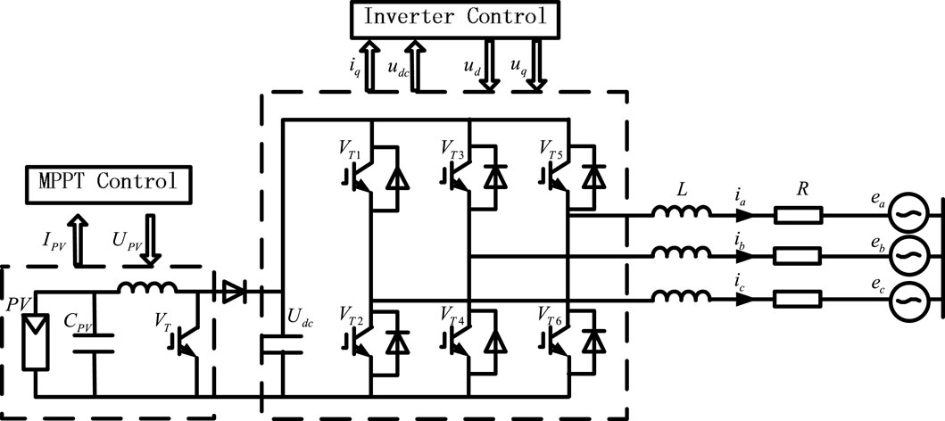
FIGURE 1. Three-phase photovoltaic grid-connected system structure diagram.
Where,
In the traditional LVRT strategy, the photovoltaic cells are always kept at the maximum power point, and only the topology of the photovoltaic system is improved or auxiliary equipment is added to consume the excess active power during the fault (Al-Shetwi et al., 2018; Zhao and Chen 2021; Yin., 2021). Not only the cost is huge, but it also has a certain impact on the stability of the system.
Photovoltaic cells are usually regarded as a current source model. Photovoltaic cells usually work in the maximum power tracking state, and the relationship between the output current
Where,
Nonlinear control method of photovoltaic power generation LVRT based on adaptive maximum power tracking, changes the terminal voltage of the photovoltaic cells through the adaptive power tracking adjustment of the photovoltaic cells during a fault. In this way, the generation of excess energy from the source is reduced. The power balance on both sides of the inverter is quickly and effectively realized, avoiding the overvoltage of the DC bus and the overcurrent of the grid-connected current. Without changing the topological structure and without adding auxiliary equipment, LVRT can be achieved well, which greatly reduces the cost of the system.
When the grid is in normal working condition, the photovoltaic power generation system will automatically track and continuously output the maximum power. Thus, the terminal voltage of the photovoltaic cells will be stable at a fixed value corresponding to the maximum power point and remain unchanged, so that the photovoltaic system can output more electrical energy.
If the power grid suddenly experiences a voltage drop fault, the power on both sides of the grid-connected inverter will not be able to maintain the original balance. At this time, the process of adaptive maximum power tracking can be changed to realize the rapid removal of faults and the rapid restoration of the inverter’s normal working state. When the system detects a voltage drop, it will actively add a voltage drop factor in the adaptive maximum power tracking process. The voltage drop factor is used to adjust the terminal voltage of the photovoltaic cells to reduce the energy emitted by the photovoltaic cells, so as to realize the control of power tracking and balance the power on both sides of the inverter. At this time, the target of adaptive maximum power tracking changes from the maximum power point to the best crossing point for LVRT.
The adaptive maximum power tracking control strategy is shown in Figure 2. Define the given value of the photovoltaic cells terminal voltage as
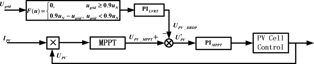
FIGURE 2. Control strategy of adaptive maximum power tracking.
When the grid voltage is within the rated value or the allowable fluctuation range, the photovoltaic power generation system remains in a normal working state, and the photovoltaic cell runs at the maximum power point (
In the process of LVRT of the photovoltaic system, in addition to controlling the output power of photovoltaic power sources, the close cooperation of photovoltaic inverters is also inseparable (He et al., 2020; Jia et al., 2020; Li et al., 2021). The grid-connected photovoltaic inverter needs to provide reactive current to the grid when the grid voltage drops to support the recovery of the grid voltage, which is another key to meeting the requirements of photovoltaic LVRT.
Among the existing control methods of grid-connected inverters, voltage control, current control, and double closed-loop control methods of voltage and current still occupy the mainstream. Although these control methods can achieve stable and controllable bus voltage or current, their disadvantages such as difficulty in parameter adjustment, large overshoot, and long system recovery time are becoming increasingly apparent.
The nonlinear control method of grid-connected inverter proposed in this paper can quickly identify the depth of grid voltage sag and issue appropriate reactive power to support the recovery of grid voltage. It has significant advantages in accelerating the response and adjustment speed of the system, restraining the overshoot of the system in the case of rapid changes, realizing rapid and effective system recovery, and reducing costs.
The following is a detailed analysis of the nonlinear control strategy of the grid-connected inverter. From Eq. 1, based on the grid voltage orientation for system control, the instantaneous active power p in the rotating coordinate system is:
Eq. 3 shows that the control of the DC voltage of the grid-connected inverter can be realized by the control of the active current
The active current of the inverter is related to the DC voltage control. And during LVRT, the reactive current of the inverter needs to be controlled. Therefore, the two most important variables selected for nonlinear control are DC voltage
According to Eq. 4, there are:
Because the grid-connected current control is finally realized by changing the output voltage vector on the inverter bridge side, the input vector of the nonlinear control can be
Since the determinant of the matrix is not 0, Eq. 6 can be written as:
Where:
The photovoltaic grid-connected inverter nonlinear control block diagram is shown in Figure 3. The reactive current command
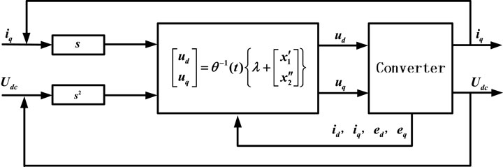
FIGURE 3. Non-linear control strategy of grid-connected inverter.
A simulation model of a three-phase photovoltaic grid-connected system with a capacity of 9kw is established in PSCAD to verify the feasibility of the proposed control strategy. The photovoltaic cells parameters in the simulation system are as follows: maximum power
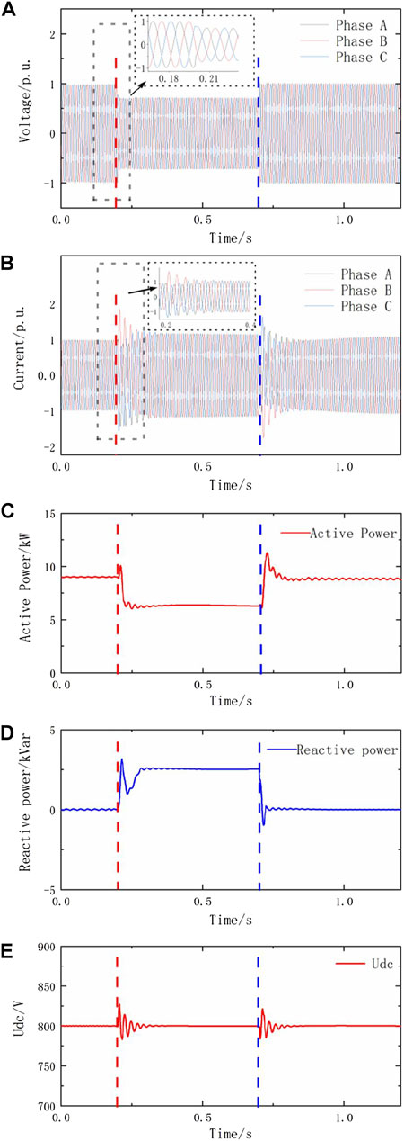
FIGURE 4. Results of control simulation when a slight voltage drops to 70%. (A–E) power Q and DC bus voltage Udc.
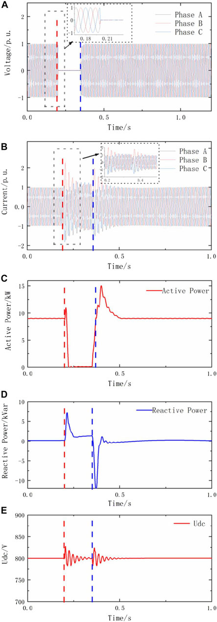
FIGURE 5. Results of control simulation when a zero voltage drop fault occurs. (A–E) power Q and DC bus voltage Udc.
Figure 4 and Figure 5 simulate the dynamic changes of photovoltaic system parameters, using the nonlinear control method of photovoltaic power generation LVRT based on adaptive maximum power tracking, when the grid voltage drops in different amplitudes, especially when zero voltage drop occurs.
Figure 4 simulates the situation when a slight voltage drop fault occurs in the power grid. As shown in Figure 4A, at t = 0.2s, the power grid suddenly experienced a voltage drop fault, and the power grid voltage dropped to 0.7 p. u. lasts 0.15s. From Figure 4B, it can be found that during the 0.15s voltage drop, the magnitude of the grid-connected current never exceeds the maximum limit. It only slightly fluctuates at the beginning and ending of the fault. Therefore, the relay protection device will not act, and the power electronic devices will not be damaged. Similar to the grid-connected current, in Figure 4E, the bus voltage only fluctuates slightly when the fault occurs and ends without exceeding the limit. During the whole fault process, the bus voltage level remained at around 800V, which was relatively stable.
Figure 4C reflects the change of active power during the voltage sag. When a fault occurs, the active power sent by the system drops significantly. At this time, the grid-connected inverter using the nonlinear control method responds quickly and injects a reactive current corresponding to the depth of the voltage drop to provide sufficient reactive power support for the system. Observing Figure 4D, it can be seen that the reactive power of the system increases rapidly from 0 Var to 2,500 Var, which is basically the same as the power calculated by the reactive current value required in the China standard and tracking the grid voltage drop. In the fault phase, the terminal voltage of the photovoltaic cell decreases, and then the power emitted by the photovoltaic cells decreases. At the end of the fault, the photovoltaic cells terminal voltage quickly recovered to the value before the drop. From the above analysis, it can be seen that when the voltage drop is not large, the nonlinear control method of photovoltaic power generation LVRT based on adaptive maximum power tracking can well realize the LVRT of the photovoltaic grid-connected system.
Figure 5 simulates the situation when a zero voltage drop fault occurs in the power grid. At t = 0.2s, the grid voltage dips to 0, and continues until the fault ends at t = 0.35s. Observing Figure 5A, it can be seen that when the nonlinear control method of photovoltaic power generation LVRT based on adaptive maximum power tracking is adopted, the photovoltaic system can maintain 150 ms without going off the grid. From Figure 5B, it can be found that the grid-connected current is only slightly different except when the fault occurs and ends. At the beginning and the ending of the fault, the grid-connected current fluctuates briefly. Except for these moments, the rest of the time can basically remain stable and not exceed the maximum limit, which meets the relevant requirements of the China State Grid.
In addition, the requirements for photovoltaic LVRT also make the following provisions for reactive power: when the grid voltage is less than 40% of the rated value, the grid-connected current should all be reactive current, and the active current should be 0. Observing Figure 5C and Figure 5D, it is obvious that the actual simulation results meet the above regulations very well. It can be seen from Figure 5C and Figure 5D that when a zero-voltage fault occurs in the power grid, the active power quickly drops to 0, and the grid-connected current components are all reactive currents. Because the grid voltage dips to 0 at that time, the reactive power is also reduced to 0. Besides, as shown in Figure 5E, during the fault, the DC bus voltage does not exceed the limit and the photovoltaic cells terminal voltage drops close to zero. After 0.15s, when the system voltage recovers, the DC bus voltage returns to normal and the photovoltaic cells terminal voltage also recovers.
The above analysis shows that when the grid drops to zero voltage, the nonlinear control method of photovoltaic power generation LVRT based on adaptive maximum power tracking can still meet the various requirements of the China State Grid, and achieve LVRT smoothly and quickly.
This paper conducts related research on the LVRT process of the three-phase photovoltaic grid-connected system when the grid voltage has a three-phase symmetrical drop.
(1) Without changing the original configuration of the three-phase photovoltaic grid-connected system and adding additional equipment, this paper proposes a new type of adaptive maximum power tracking low voltage ride-through control strategy. Using the proposed strategy, the terminal voltage of the photovoltaic cells are changed by adjusting the power tracking trajectory through the feedforward of the voltage drop amplitude. Thereby, the photovoltaic cells power output is quickly and effectively controlled, which ensures the balance of power on both sides of the inverter, accurately and effectively suppresses the increase in DC bus voltage, and maintains the stability of the DC bus voltage.
(2) In addition, based on the disadvantages of the existing control strategy of the grid-connected inverter, this paper also proposes a non-linear control method, which can speed up the adjustment of the system. The response speed enables the grid-connected output current to provide as much active power support for the grid as possible without exceeding the limit. And at the same time, a certain amount of reactive power will be emitted to maximize the support for the restoration of the grid voltage.
(3) The simulation results confirm that when the grid voltage drops in different amplitudes, especially when it drops to zero voltage, the nonlinear control method of photovoltaic power generation LVRT based on adaptive maximum power tracking can well realize the LVRT of the photovoltaic grid-connected system.
The original contributions presented in the study are included in the article/Supplementary Material, further inquiries can be directed to the corresponding author.
JY: methodology and writing. HN and XH: software and data curation. GX and JX: resources and investigation. YL: software implementation.
This work is supported by the Key scientific research projects of colleges and universities in Henan Province (19A470003).
The authors declare that the research was conducted in the absence of any commercial or financial relationships that could be construed as a potential conflict of interest.
All claims expressed in this article are solely those of the authors and do not necessarily represent those of their affiliated organizations, or those of the publisher, the editors and the reviewers. Any product that may be evaluated in this article, or claim that may be made by its manufacturer, is not guaranteed or endorsed by the publisher.
Al-Shetwi, A. Q., Sujod, M. Z., and Blaabjerg, F. (2018). Low Voltage Ride-Through Capability Control for Single-Stage Inverter-Based Grid-Connected Photovoltaic Power Plant. Solar Energy 159, 665–681. doi:10.1016/j.solener.2017.11.027
Benali, A., Khiat, M., Allaoui, T., and Denai, M. (2018). Power Quality Improvement and Low Voltage Ride through Capability in Hybrid Wind-PV Farms Grid-Connected Using Dynamic Voltage Restorer. IEEE Access 6, 68634–68648. doi:10.1109/access.2018.2878493
Elazab, O. S., Debouza, M., Hasanien, H. M., Muyeen, S. M., and Al‐Durra, A. (2020). Salp Swarm Algorithm‐based Optimal Control Scheme for LVRT Capability Improvement of Grid‐connected Photovoltaic Power Plants: Design and Experimental Validation. IET Renew. Power Generation 14 (4), 591–599. doi:10.1049/iet-rpg.2019.0726
Fan, S., Chao, P., and Zhang, F. (2017). Modelling and Simulation of the Photovoltaic Power Station Considering the LVRT and HVRT. J. Eng. 2017 (13), 1206–1209. doi:10.1049/joe.2017.0520
Han, P., Fan, G., Sun, W., Shi, B., and Zhang, X. (2019). Research on Identification of LVRT Characteristics of Photovoltaic Inverters Based on Data Testing and PSO Algorithm. Processes 7 (5), 250. doi:10.3390/pr7050250
He, Y., Wang, M., Jia, Y., Zhao, J., and Xu, Z. (2020). Low‐voltage Ride‐through Control for Photovoltaic Generation in the Low‐voltage Distribution Network. IET Renew. Power Generation 14 (14), 2727–2737. doi:10.1049/iet-rpg.2019.1101
Huka, G. B., Li, W., Chao, P., and Peng, S. (2018). A Comprehensive LVRT Strategy of Two-Stage Photovoltaic Systems under Balanced and Unbalanced Faults. Int. J. Electr. Power Energ. Syst. 103, 288–301. doi:10.1016/j.ijepes.2018.06.014
Jia, J., Yan, X., Wang, Y., Aslam, W., and Liu, W. (2020). Parameter Identification and Modelling of Photovoltaic Power Generation Systems Based on LVRT Tests. IET Generation, Transm. & Distribution 14 (15), 3089–3098. doi:10.1049/iet-gtd.2019.1730
Li, Y., Yang, X., and Chen, W. (2018). Neutral-point Voltage Analysis and Suppression for NPC Three-Level Photovoltaic Converter in LVRT Operation under Imbalanced Grid Faults with Selective Hybrid SVPWM Strategy. IEEE Trans. Power Electro. 34 (2), 1334. doi:10.1109/TPEL.2018.2834226
Li, Y., Han, M., Yang, Z., and Li, G. (2021). Coordinating Flexible Demand Response and Renewable Uncertainties for Scheduling of Community Integrated Energy Systems with an Electric Vehicle Charging Station: A Bi-level Approach. IEEE Trans. Sustain. Energ. 12 (4), 2321–2331. doi:10.1109/tste.2021.3090463
Li, Y., Li, J., and Wang, Y. (2022a). Privacy-preserving Spatiotemporal Scenario Generation of Renewable Energies: A Federated Deep Generative Learning Approach. IEEE Trans. Ind. Inf. 18 (4), 2310–2320. doi:10.1109/tii.2021.3098259
Li, Y., Wang, R., and Yang, Z. (2022b). Optimal Scheduling of Isolated Microgrids Using Automated Reinforcement Learning-Based Multi-Period Forecasting. IEEE Trans. Sustain. Energ. 13 (1), 159–169. doi:10.1109/tste.2021.3105529
Li, Z., Lu, J., Liu, J., Zhu, Y., and He, Q. (2020). Resistance Selection and Control Strategy Considering the Coordination of Protection Performance and Low Voltage Ride through of a Large-Scale Photovoltaic Power Station. IEEE Access 8, 143746–143758. doi:10.1109/access.2020.3014232
Ma, J., and Liu, J. (2018). Adaptive Directional Current protection Scheme Based on Steady State Component in Distribution Network with DG. Electric Power Automation Equipment 38 (1), 1–9. doi:10.16081/j.issn.1006-6047.2018.01.001
Nasiri, M., Arzani, A., and Guerrero, J. M. (2021). LVRT Operation Enhancement of Single-Stage Photovoltaic Power Plants: An Analytical Approach. IEEE Trans. Smart Grid 12 (6), 5020–5029. doi:10.1109/tsg.2021.3108391
Qian, W., Zhou, N., Wu, J., Li, Y., Wang, Q., and Guo, P. (2019). Probabilistic Short-Circuit Current in Active Distribution Networks Considering Low Voltage Ride-Through of Photovoltaic Generation. IEEE Access 7, 140071–140083. doi:10.1109/access.2019.2944195
Sajadian, S., and Ahmadi, R. (2018). ZSI for PV Systems with LVRT Capability. IET Renew. Power Generation 12 (11), 1286–1294. doi:10.1049/iet-rpg.2018.5104
Telukunta, V., and Pradhan JAgrawal, A. (2018). Protection Challenges under Bulk Penetration of Renewable Energy Resources in Power Systems:A Review. CSEE J. Power Energ. Syst. 3 (4), 365. doi:10.17775/CSEEJPES.2017.00030
Yin, J. (2021). Research on Short-Circuit Current Calculation Method of Doubly-Fed Wind Turbines Considering Rotor Dynamic Process. Front. Energ. Res. 9, 204. doi:10.3389/fenrg.2021.686146
Zangeneh Bighash, E., Sadeghzadeh, S. M., Ebrahimzadeh, E., and Blaabjerg, F. (2018). Improving Performance of LVRT Capability in Single-phase Grid-Tied PV Inverters by a Model-Predictive Controller. Int. J. Electr. Power Energ. Syst. 98, 176–188. doi:10.1016/j.ijepes.2017.11.034
Zhang, Y., Wang, J., Li, H., Zheng, T. Q., Lai, J.-S., Li, J., et al. (2020). Dynamic Performance Improving Sliding-Mode Control-Based Feedback Linearization for PV System under LVRT Condition. IEEE Trans. Power Electron. 35 (11), 11745–11757. doi:10.1109/tpel.2020.2983315
Keywords: photovoltaic power generation, LVRT, nonlinear control method, adaptive maximum power tracking, grid-connected inverter
Citation: Yin J, Nie H, Huang X, Xu G, Xu J and Liu Y (2022) Nonlinear Control Method of Photovoltaic Power Generation LVRT Based on Adaptive Maximum Power Tracking. Front. Energy Res. 10:900120. doi: 10.3389/fenrg.2022.900120
Received: 20 March 2022; Accepted: 13 April 2022;
Published: 09 May 2022.
Edited by:
Chen Chen, Xi’an Jiaotong University, ChinaReviewed by:
Meng LI, Beijing Jiaotong University, ChinaCopyright © 2022 Yin, Nie, Huang, Xu, Xu and Liu. This is an open-access article distributed under the terms of the Creative Commons Attribution License (CC BY). The use, distribution or reproduction in other forums is permitted, provided the original author(s) and the copyright owner(s) are credited and that the original publication in this journal is cited, in accordance with accepted academic practice. No use, distribution or reproduction is permitted which does not comply with these terms.
*Correspondence: Jun Yin, eWluanVuQG5jd3UuZWR1LmNu
Disclaimer: All claims expressed in this article are solely those of the authors and do not necessarily represent those of their affiliated organizations, or those of the publisher, the editors and the reviewers. Any product that may be evaluated in this article or claim that may be made by its manufacturer is not guaranteed or endorsed by the publisher.
Research integrity at Frontiers
Learn more about the work of our research integrity team to safeguard the quality of each article we publish.