- 1College of Energy and Power Engineering, Lanzhou University of Technology, Lanzhou, China
- 2College of Water Resources and Architectural Engineering, Northwest A&F University, Yangling, China
When a pump is propelled by a propeller, the nozzle flooding of the jet wake area will produce a turbulent quasi-sequence structure and have a certain impact on the outflow field structure and thrust characteristics of the water jet propulsion pump. In this paper, a method that combined numerical simulation with vortex dynamics is adopted, which analyzes the dynamic characteristics and influence on the thrust characteristics of the water jet propulsion pump. A large eddy simulation turbulence model and a dimensionless water jet propulsion pump velocity coefficient were used to reveal flow structure and relation, with the pump operation parameters of the wake vortex ring. The thrust with a trailing vortex ring is 7.0% higher than that without a trailing vortex ring. Vortex dynamics and mathematical statistics are combined to quantitatively analyze the dynamic characteristics of the jet tail vortex ring. Finally, the formation time of the vortex ring is obtained in exponential relation with dimensionless transmission velocity and vorticity coefficient, which has nonlinear relation with vortex intensity coefficient and helicity coefficient. BP Neural Network combined with the LM algorithm is used to establish the mathematical relationship between the thrust and the physical characteristic parameters of the vortex ring.
1 Introduction
Jet flow is a movement phenomenon in which the fluid flows into another working medium and shoots out from the nozzle or slit. The difference between jet flow and pipe flow is that pipe flow is surrounded by a solid container, while jet flow is uncontained except for the water jet. Most jets are surrounded by fluid (June 1995; HE et al., 2001). In the spraying process of the nozzle of the water jet propulsion pump, both the working fluid and the environmental fluid are water, that is, the jet is a submerged jet. In the whole process of jet movement, vortex pairs and merge with each other due to the shear action of the jet boundary, which exchanges momentum and mass with the surrounding fluid. The vortex makes the surrounding medium flow with the jet, which increases the flow rate and enlarges the cross-section.
At present, domestic and foreign researchers all mainly focus on numerical simulation, experimental research, and theoretical analysis to study jet flow. Yanling Li (Li, 2004) used 3D numerical simulation to study the flow characteristics and vortex structure of the multi-level submerged jet. She not only described the energy dissipation mechanism of the multi-level submerged jet from two aspects of theoretical analysis and numerical simulation but also observed the whole dissipation process by experimental study. Experimental results showed that the multi-level submerged jet was technically feasible and had the characteristics of significant energy dissipation and a stable flow state. For the quasi-sequence structure generated by the jet, Brown (Brown, 1935) carried out experiments with the jet in the form of a slit. The eddy current structure was observed to change alternately on both sides of a plane jet by the flow display method. The effect of forced jet force on eddy current was studied. The basic law of vortex motion in the jet is obtained by experiment. However, there was no good mathematical model for the observed vortex rate. Davies et al. (Davies et al., 1963) focused on the study of organized motion in turbulent free-shear flow. During the study, a series of vortices were observed to generate continuously near the jet outlet. Experiments showed that there were also significant differences between the time average scalar field and the instantaneous scalar field. The former showed a strong Gaussian distribution, while the latter showed a strong high-order distribution. Becker and Massaro (Becker and Massaro, 1968) focused on the study of flow visualization and observed annular vortices at the initial stage of turbulent jet flow. They considered that the thickness of the boundary layer at the jet outlet was the controlling factor of the disturbance growth. Experiments showed that the turbulent integral time scale becomes inversely proportional to the local tangent in the coordinate system of maximum energy convection in turbulent motion. Mungal et al. (Mungal and Hollingsworth, 1989) studied the vortex structure of relevant jets at a high Reynolds number. He mainly discussed the mechanism of entrainment of ambient fluid by jet. LYDIA. RUIZ et al. (Ruiz et al., 2011), departments of Mechanical Engineering, California Institute of Technology, United States, showed that coherent vortex structures could be generated in the near wake of self-propelled aircraft. The structure could improve the efficiency of propulsion by controlling the local pressure field and entrainment motion. Vortex formation was used to control the near-wake characteristics, which can greatly improve the propulsion efficiency. This was more than 50% better than the performance of the steady jet mode. Compared with stable jet propulsion, Yang Xiang et al. (Xiang et al., 2018) showed that pulsed jet propulsion can show higher efficiency by forming unstable vortex rings. This means that energy can be better transferred and stored in eddy currents to produce propulsion. The mode of effective propulsion in the process of vortex ring energy evolution was illustrated. They pointed out that increasing the energy contribution to the eddy can further enhance propulsive performance. Mark A. Grosenbaugh (Wang, 2020) and researchers studied laminar vortex rings under the influence of background flow using numerical simulation methods. They explained that long, continuous jets maximize thrust for a given amount of energy expend.
Although many scholars have studied the problem of flood jets, they mainly focus on practical applications, and rarely study the flow characteristics of flood jets; especially under the conditions of various vortex topologies, flood jets have unstable flow characteristics. By simulating the vortex ring structure generated in the submerged jet wake, this paper analyzes the hydrodynamics of the whole water jet propulsion device combined with the submerged jet at the tail of the water jet propulsion pump. The influence of the wake vortex ring on the thrust characteristics of the water jet propulsion unit is explained. In this paper, the spiral mixed-flow water jet propulsion pump is selected as the main power component of the vortex ring. The trailing vortex ring generated by the jet is taken as the study object. Based on the experimental verification of thrust characteristics, the CFD method was used to simulate the submerged jet flow process of the water jet propulsion pump. The induction mechanism of the jet tail vortex ring and its response to thrust characteristics were observed. This provides a reference for further research and application of the submerged jet sequence structure.
2 Numerical Simulation of Jet Wake Vortex Ring of Water Jet Propulsion
2.1 Three-Dimensional Modeling of Flow-Through Components of Water Jet Propulsion Pump
In this paper, the spiral mixed flow water jet propulsion pump with the specific speed of
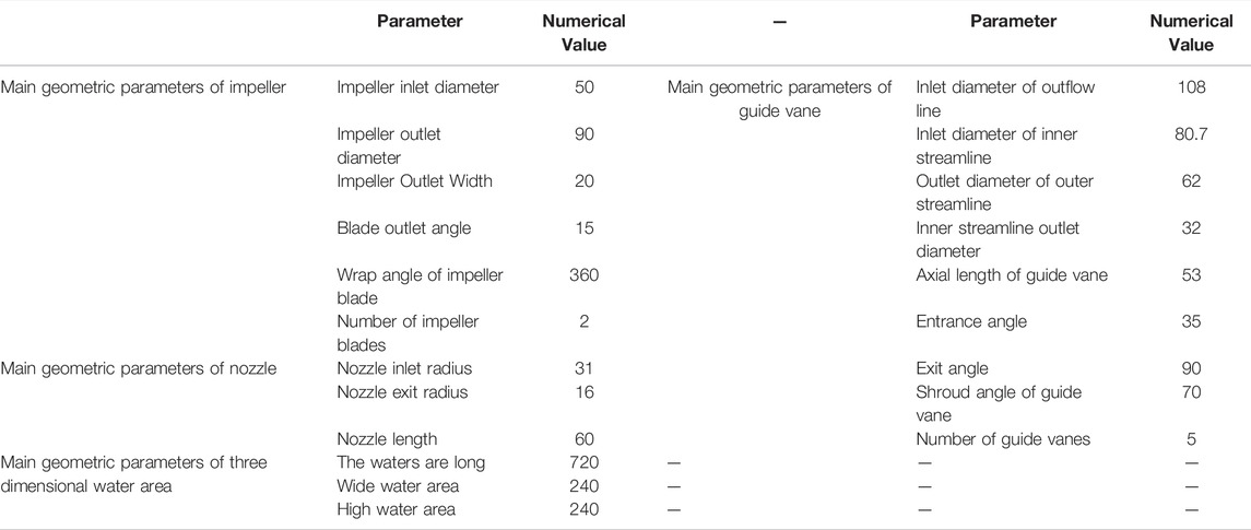
3d drawing software is used for geometric modeling of the water jet propulsion pump. As the core power components of the water jet propulsion pump, the impeller transfers mechanical energy to the fluid through blade rotation. It can increase the static and dynamic pressure energy. This is mainly for energy conversion. Guide vane is the axial length and radical short distribution. Its main function is to eliminate the circumferential component of the fluid flowing through the impeller and convert part of the kinetic energy into pressure energy. In order to ensure uniform flow, the inlet extension section is usually added at the inlet end of the impeller and the length is usually four times the inlet diameter of the impeller. The computational domain model of the flow-through components of the whole water jet propulsion pump is shown in Figure 1. The main geometric dimensions are presented in Table 1.

FIGURE 1. Computational domain model diagram of flow through components of water jet propulsion pump.
2.2 Numerical Simulation of Jet Flow on the Propulsion Pump
2.2.1 Mesh Generation
In this paper, the flow area diagram and water area diagram of each component of the water jet propulsion pumps are divided into grids. It is difficult to divide the impeller and guide the vane of the water jet propulsion pump by using structured mesh because they both contain curved surfaces with large curvature changes. In order to facilitate the encryption of some local areas, the impeller and guide vane of a water jet propulsion pump is divided into unstructured grids in this paper. In order to capture the development and evolution process of jet tail vortex rings in water jet propulsion, the reasons for a large number of unstructured grids are considered. It divides the inlet end, nozzle, and water body of the water jet propulsion pump with regular shapes into the structured grid with high grid quality and easier access to the actual model. The grid division results of each component are shown in Figure 2.
The grid of each part is combined to obtain the overall and water area grid of the water jet propulsion pump, as shown in Figure 3.
2.2.2 Grid Independence Test
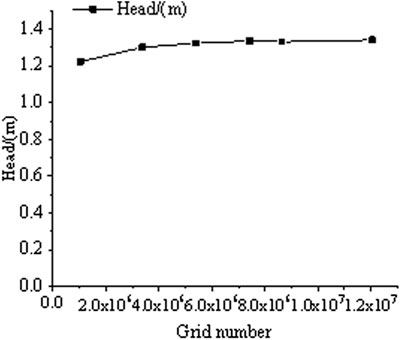
In this paper, large eddy simulation (LES) is used in the design conditions. Six groups of computing models with different mesh numbers are selected for steady numerical simulation. Head is used as a test criterion for grid independence. Based on ensuring that the mesh quality of impeller and guide vane reaches 0.35 or above, and the mesh quality of inlet section, nozzle, and water area reaches 0.8 or above. By adjusting the grid-scale and the number of grid nodes, the number of grids is obtained as 194,7033, 407,3634, 595,5588,777,8075, 891,2579, and 1202,7317, respectively. The relationship between the grid number and the head is plotted as shown in Figure 4. From Figure 4, it can be seen that the relative errors among the grids of six different sizes are small and all within 0.3%.
When the solution accuracy and computational resources are both considered, the number of grids is 7.7780750 million and above, and the different rate of the pump head is small. Therefore, we finally selected the grid number 7.778,075 million for numerical simulation.
2.3 Numerical Calculation Method of the Jet Wake Vortex Ring in Water Jet Propulsion
2.3.1 Turbulence Model
In this paper, the three-dimensional unsteady large eddy simulation is used to study the water jet submerged jet. It is obtained the detailed flow field information in the wake region of the submerged jet under different working conditions and the three-dimensional evolution characteristics of the large-scale vortex structure formed near the region.
Large-eddy simulation (LES) is used to filter transient and Navier-Stokes equations in the spatial domain. The small-scale vortices that are smaller than the width of the filter or the scale of the computational grid can be filtered out by the filtering process. It forms the governing equation of large vortices. The small-scale vortex is described by simulation (Wang, 2020).
2.3.2 Control the Numerical Solution of Equations
The numerical solution of the governing equation is obtained by distillation of the algebraic equation. At the same time, the approximate solution of the actual flow field can be obtained by this process. At present, the main flow field solution methods include the coupling solution method and separation solution method. These two methods are divided according to the analytic order and adjustment of unknowns. The coupling methods can deal with the relationship between density, energy, and momentum in the flow field. The core idea of the separation method is to revise and reiterate the repeated pressure until the solution converges. It has been widely used in the numerical solution of the flow field.
In the process of numerical calculation, the SIMPLC algorithm modified pressure and velocity to a certain extent. This accelerates the convergence rate and establishes algebraic modified equations of pressure and velocity. Therefore, the finite volume method is used in this paper to discretize the flow field equations of water jet propulsion. In order to achieve high convergence accuracy, SIMPLC algorithm is used to solve the flow field in this paper.
2.3.3 Vorticity Distribution in Jet Wake Area of Water Jet Propulsion
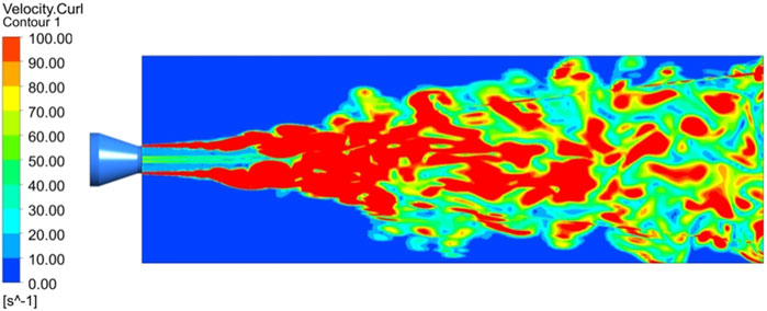
As shown in Figure 5, it can be seen from the distribution of the entire vortex cloud map that the distribution of eddy intensity on the upper and lower sides is basically the same, and the vorticity vector direction is opposite. At the same time, the vorticity on the upper and lower sides of the axis has relatively obvious symmetrical distribution characteristics, which is because the axis is the core area of the jet, which can generate higher vorticity, that is, the shear effect and mixing between the nozzle jet and the tailwater area action leads to the forward transmission and dissipation of energy.
In the region near the nozzle, the vorticity value is relatively large, which is due to the high initial kinetic energy and strong clustering of the jet in the initial stage of the convergent nozzle. With the continuous development of the jet, the jet beam expands continuously along the radial direction, the jet fluid continuously interacts with the surrounding water body, and the energy dissipates gradually. At the same time, vorticity values generally show a downward trend, and the edge of the vorticity concentration area slowly generates smaller-scale vortices. The vorticity distribution in the whole wake area directly reflects the vorticity evolution characteristics of the submerged jet of the three-dimensional nozzle.
2.3.4 Pressure Distribution in the Wake of Water Jet Propulsion
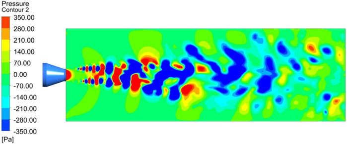
As shown in Figure 6, there is a low-pressure area in the region near the nozzle outlet, which is caused by the weak interaction between the nozzle outlet and the surrounding fluid due to the low velocity of the nozzle outlet. Along the axis of the jet flow direction, the vortex street phenomenon is evenly distributed on both sides of the whole jet wake area, and the pressure values of the upper and lower vortices are both the same. At the same time, the pressure distribution between two adjacent vortex pairs presents a positive and negative distribution, and the absolute value of pressure is the same. As the flow continues, the symmetry between the upper and lower vortices is gradually destroyed due to the dissipation of energy.
As the flow continues, due to the strong shear effect between the jet and the wake, a pair of small vortices with symmetrical distribution near the nozzle is formed at the beginning of the nozzle injection, and the pressure values of the small vortices on both sides are the same. When the vortices flow downstream along the flow direction, they gradually merge with the vortices of different scales formed in front of them. In the far-field region near the nozzle exit, the symmetry of the large and small vortices gradually disappears with the dissipation of energy, and the vortices of each scale are distributed irregularly.
2.3.5 Velocity Streamline Distribution in the Wake of Water Jet Propulsion
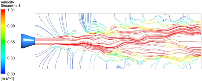
As shown in Figure 7, when the water in the nozzle is ejected, it is not an imaginary direct-current jet, but will be squeezed by the surrounding water and rolled back to form a vortex ring structure. After the jet fluid accelerates fluid through the tapered nozzle, it first forms a DC liquid in the area near the nozzle, and then with the process of spraying, the ejected water gradually begins to suck up the water in the surrounding environment, making the main jet the flow on both sides of the flow area exists in the form of vortex rings, which increases the entrainment effect of environmental fluid (i.e., the volume of the whole wake area).
The main jet area continuously entrains the surrounding fluid and moves forward, causing the surrounding fluid to bend along the jet direction, thus the streamline distribution in the main jet area is no longer stable, the water flow is gradually dispersed, and vortices of various scales continue to propagate backward along the diffusion surface. As the injection proceeds, the entrainment continues. On the upper side of the nozzle main jet area, the vortex distribution is anticlockwise, while on the lower side, the vortex distribution is clockwise. The difference in the direction of vortex distribution is caused by the different entrainment directions of jet flow on the surrounding fluid.
2.4 Thrust Verification of Jet Wake Vortex Ring Simulation for Water Jet Propulsion
Like other underwater bio-jet modes, the thrust generated during the jet propulsion pump can be obtained according to the momentum conservation law and the momentum theorem. Suppose that the outflow velocity of the nozzle of the water jet propulsion pump at time
In Eq. 1,
Figure 8A,B respectively show the changeable curve of the relationship between the thrust generated by the helical mixed-flow jet propulsion pump and the average thrust generated by the pump-water integrated system with the impeller speed and inlet flow rate. According to the characteristic curves of impeller speed and average propulsion force in Figure 8A, the thrust of the spiral mixed-flow pump and the pump-water integrated system both increase gradually with the change of rotational speed at a given design speed of 1500 r/min. The variation rate of the pump-water system is larger than the spiral mixed-flow pump. The main reason for this situation is that in the spiral mixed flow pump, the pump thrust only needs to be provided by the reaction force generated by the water flowing out of the nozzle due to Newton’s third law. In the pump-water integrated system, the thrust generated by the pump-jet thruster is in addition to the above reaction force. As the jet fluid pulls in the surrounding fluid, causing the fluid to accelerate, the water allows the eddy currents to increase part of the thrust of the propulsion. This part of the thrust can compensate for some of the drag in the propulsion system compared to the spiral mixed flow pump. By calculation, the propulsion force produced by the pump-water integrated system is about 6%–7% higher than that produced by the simple spiral mixed flow pump.
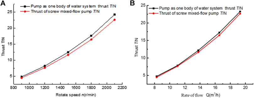
FIGURE 8. Characteristic curve of water jet propulsion pump. (A) N-T characteristic curve of water jet propulsion pump. (B) Q-T characteristic curve of water jet propulsion pump.
It can be seen from the characteristic curve of inlet flow rate and average propulsion force in Figure 8B that the thrust of the spiral mixed-flow pump and the pump-water integrated system have basically the same change trend with inlet flow rate. The reason for the slightly higher thrust in the pump-water integrated system is that the entrainment of environmental fluid in the wake area of the nozzle area becomes more significant with the increase of inlet flow. This causes fluid acceleration in the wake area. It is calculated that the propulsive force produced by the pump-water integrated system is about 9% higher than that produced by the spiral mixed-flow pump. Therefore, under the given conditions, accelerating the impeller speed to provide unstable flow and adopting a larger inlet flow rate will greatly enhance the propulsion effect. This also explains that in the jet propulsion process, the contribution of vortex propulsion is enhanced by entrainment of ambient fluid and downstream acceleration of near wake vortex. It reduces the systematic resistance of the entire jet propulsion process.
3 Dynamic Characteristics of a Jet Tail Vortex Ring in Water Jet Propulsion
3.1 Mathematical Model of Jet Wake Vortex Ring
The vortex ring is a flow structure with axisymmetric characteristics in the cylindrical coordinate system
Norbury (Norbury, 1973) classified vortex rings according to the dimensionless vortex core radius
Where,
Sullivan (Sullivan et al., 2008) researched the model of thin core vortex rings through the experimental study of piston devices. The changes in the physical characteristics of the vortex ring can be calculated by the growth state of the vortex ring as follows:
In the equation,
3.2 Energy Transfer Model of Water Jet Propulsion
The basic principle of water jet propulsion is similar to that of aero engines. It uses the momentum difference between the inlet and outlet of the propulsion system to generate thrust and propel the ship. In the water jet propulsion system, there is an energy transfer model, as shown in Figure 9.
The Bernoulli equation between the pump inlet flow surface and the nozzle is:
Where Z is the height of the cross-section relative to the free flow surface m;
It is assumed that the static pressure of the pump inlet surface and the nozzle is equal to the local atmospheric pressure, and the height of the flow section is equal to the height of the free flow surface. It expresses the inlet passage and nozzle loss head as a percentage of
Where
ξ is the pipeline loss coefficient, equal to the sum of the above two loss coefficients;
The head provided by the water jet pump is mainly used to increase the kinetic energy of the working fluid after overcoming line losses. Part of the increased velocity of the working fluid was converted to a useful head. The other part is to overcome the jet loss.
Where:
The first term on the right is the useful head. The second item is the jet head.
3.3 Physical Characteristic Parameters of Jet Wake Vortex Ring in Water Jet Propulsion
At present, domestic and foreign scholars’ research on jet propulsion mode focuses on self-propelled aircraft and underwater organisms, mainly involving theoretical research, experimental research, and irregular calculation of flow field in CFD numerical simulation. In the research process of the vortex ring, Saffman (Saffman, 1978), Norbury (Amick and Fraenkel, 1988), and Fabris (Fabris and Liepmann, 1997) have studied that the vortex ring has an obvious vortex structure. However, determining which parameters affect the formation and physical characteristics of vortex rings is a difficult problem in vortex ring research. The theoretical analysis, numerical simulation, and experimental study of water jets advance the vortex under submerged jet conditions are lack of systematic knowledge system. In order to fully understand the instability mechanism of the water jet propulsion submerged jet, the physical characteristics of the water jet propulsion jet tail vortex ring are discussed on the basis of previous research.
3.3.1 Formation Time of Trailing Vortex Ring
The formation process of a jet tail vortex ring in water jet propulsion is the process of continuous ejection of fluid in a nozzle and continuous entraining of the surrounding fluid. It is found that when the water behind the nozzle is a static flow field, the main parameter affecting the structure of the vortex ring is the vortex ring formation time
In Eq. 15,
Water jet propulsion mode mainly includes short pulse jet and long pulse jet. The fundamental difference between the two jets lies in the time of vortex ring formation. Generally,
By monitoring the velocity of the water jet at different times, it is found that the jet of spiral mixed flow water jet propulsion pump belongs to the long pulse jet. This jet carries more water downstream from the surrounding waters than the DC liquid. This increases the additional pressure on the nozzle and enhances the effect of jet propulsion.
3.3.2 Kinematic Parameters of Wake Vortex Ring
Kinematic parameters of the wake vortex ring mainly refer to the transmission speed of the vortex ring induced by water at different times. It also refers to the induced velocity sum of water area as
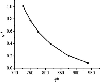
The change of dimensionless transmission speed of vortex rings under different formation times is shown in Figure 10.
As can be seen from the figure above, the dimensionless transmission speed of the vortex ring changes exponentially with the formation time. Combined with mathematical statistical analysis, the dimensionless transmission speed and vortex ring formation time can be expressed as follows:
3.3.3 Dynamic Parameters of Wake Vortex Ring
In order to study the structure, evolution, and interaction of vortex rings in water jet propulsion, this section analyzes the trailing vortex rings generated under design conditions of water jet propulsion pumps based on vorticity, vortex strength, and helicity of the vortex dynamic diagnosis method. The vortex dynamics method can accurately capture the variation of vortex ring structure and strength in the wake region of jet propulsion.
The curl of the transmission velocity
Vortex intensity S is introduced into the quantitative analysis of jet tail vortex rings. It describes the intensity of a turbulent vortex. The calculation formula is as follows:
Where
Helicity is an important parameter used to measure the topological structure of the turbulent vorticity field. The helicity in the three-dimensional flow field of water jet propulsion is defined as:
It is called the helicity density by the product, and the units of helicity are
As for the kinematic parameters of trailing vortex rings, the mathematical models of each parameter and the formation time of vortex rings are established at the level of vortex dynamics. It reintroduces the dimensionless vorticity coefficient
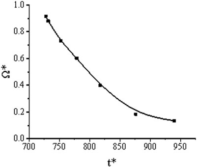
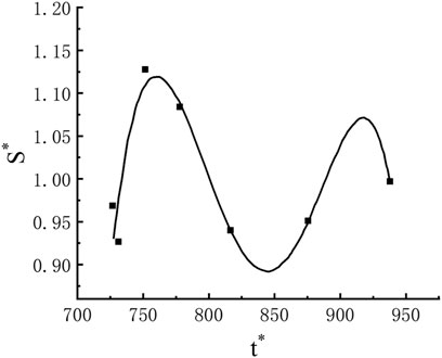
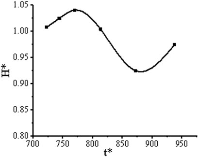
The monitoring of each dynamic parameter at different times in the design condition is calculated. The variation of the formation time of different vortex rings with each dimensionless parameter is shown in Figures 11–13.
As can be seen from Figure 11, the formation time of the vortex ring changes exponentially with the vorticity coefficient. The dimensionless vorticity coefficient and vortex ring formation time can be expressed as:
It can be seen from Figure 12 that the formation time of the vortex ring and vortex strength coefficient are non-linear. The function expression of the vortex strength coefficient and vortex ring formation time obtained by the mathematical statistical method is:
It can be seen from Figure 13 that the formation time of the vortex ring and the helicity coefficient are non-linear. The function expression of the helicity coefficient and vortex ring formation time obtained by the mathematical statistical method is:
Through the numerical simulation and eddy dynamic analysis of the jet propulsion jet vortex ring, it is learned that a coherent vortex structure is generated in the wake area of the water wake of the water jet propulsion nozzle tail, that is, the “jet tail vortex ring”. The main factor affecting the formation of the tail vortex ring is the time of vortex ring formation. The long-pulse jet mode has a vortex ring generated throughout the jet process. The formation of the water jet tail vortex ring is mainly due to the influence of the spray water flow by the control of the coiling action of the surrounding water body, and the vortex ring of different scales is rolled up in the near-wake of the water body through the winding action. The near-wake area of the water at the tail of the pump nozzle has the characteristics of the rapid growth of the shear layer and the winding up of the large-scale coherent vortex ring at a fixed time-frequency, and when the radial component of the velocity vector increases, the level of environmental fluid entrainment is significantly increased. The nonlinear variation relationship between the formation time of the vortex ring and the dimensionless characteristic parameters was obtained by combining vortex dynamics and mathematical statistics.
4 Mathematical Model of Jet Wake Vortex Ring on Thrust Force of the Pump
4.1 The Process of Establishing a Mathematical Model
To analyze the nonlinear mathematical relationship between the trailing vortex ring generated in the jet propulsion process and the thrust characteristics. Based on the mathematical model between the physical characteristic parameters of the wake vortex ring and the thrust, the physical characteristic parameters of the wake vortex ring under the design condition of the water jet propulsion pump were established to monitor. Finally, the mathematical model of thrust with each parameter is obtained.
Considering that the mathematical relationship between the pump-water integrated thrust and the physical characteristic parameters of the wake vortex ring is not clear, this paper uses MATLAB programming to introduce a method based on the Levenberg-Marquardt (hereinafter referred to as “LM”) training algorithm and Back Propagation Neural Network (hereinafter referred to as “BP Neural Network”) combination. It can quickly realize the modeling of the nonlinear system between the thrust of the pump water body and the physical characteristic parameters of the vortex ring.
In this paper, the physical characteristic parameters of jet tail vortex ring of water jet propulsion include vortex ring transmission speed, vorticity, vortex intensity, and helicity, and the propulsion performance parameter is thrust. Therefore, it determines the number of neurons in the BP Neural Network input layer to be four. The number of neurons in the output layer was determined to be one.
According to the empirical formula, the number of hidden layer neurons was determined as three. The structure of BP Neural Networks is shown in Figure 14.
4.2 Determination of Mathematical Model
This paper constructs the BP Neural Network with four inputs and one output. The above determination of the BP Neural Network structure shows that the input layer consists of four neurons. It is used to complete the input of four physical characteristic parameters of a jet tail vortex ring in water jet propulsion. The hidden layer consists of three neurons. It is used to complete the spatial weighting of input signals and improve the ability of complex mapping between input and output of nonlinear systems. The output layer consists of one neuron. It is used to complete the thrust output of the pump-water integrated system.
It is assumed that the signal transmitted from the input layer to the hidden layer is
The signal transmitted from the hidden layer to the output layer is denoted as
The output signal of the output layer is denoted as
The weights and biases read after the neural network training are substituted into Eq. 35.
Therefore, by combining BP neural network and LM algorithms, the physical characteristic parameters of the jet wake vortex ring of water jet propulsion are established. It is combined with the thrust to create mathematical modeling.
5 Conclusion
The submerged shear jet exists widely in the field of nature and engineering technology. The dynamic response of the jet vortex ring in the process of formation, enrolling, and mixing has a great impact on practical engineering applications. In the study of the submerged jet in the nozzle, the evolution of various scale vortex systems, especially symmetrically distributed vortex systems, in the submerged jet section is investigated by numerical simulation. Meanwhile, the interaction between vortex patterns in the water section is analyzed. This paper systematically reveals the vortex ring mechanism during nozzle injection.
The nonlinear mathematical relationship between the time of vortex ring formation and each dimensionless physical characteristic parameter is established, and the hydrodynamic theory is applied to compare the thrust characteristics generated by the pump-water system and bare pump under the same working conditions. The thrust generated is about 7% higher than in the case of the bare pump.
The combination of BP Neural Network and LM algorithm is used to realize the mathematical modeling of each parameter of thrust and jet wake vortex ring.
In future studies, it is necessary to study the jet flow under different nozzle shapes, injection angles, and nozzle outlet diameters, to fully reveal the flow mechanism and influencing factors of the jet tail vortex ring. The vortex systems with different scales generated by the jet propulsion are studied, and the vortex systems with different contributions are classified.
Data Availability Statement
The original contributions presented in the study are included in the article/Supplementary Material, further inquiries can be directed to the corresponding authors.
Author Contributions
WH: Conceptualization, Methodology. ZL:Writing- Reviewing and Editing. RL: Supervision Funding acquisition. HF: Formal Analysis. LN: Writing- Original draft preparation and Editing. JX: Resources. MX: Visualization.
Funding
This study was supported by the National Natural Science Foundation of China (Grant Nos. 52179086, 51669012) and the Central leading local science and technology development projects “Development and industrialization of Bohai bay shallow water multiphase flow meter”.
Conflict of Interest
The authors declare that the research was conducted in the absence of any commercial or financial relationships that could be construed as a potential conflict of interest.
Publisher’s Note
All claims expressed in this article are solely those of the authors and do not necessarily represent those of their affiliated organizations, or those of the publisher, the editors and the reviewers. Any product that may be evaluated in this article, or claim that may be made by its manufacturer, is not guaranteed or endorsed by the publisher.
References
Amick, C. J., and Fraenkel, L. E. (1988). The Uniqueness of a Family of Steady Vortex Rings. Arch. Ration. Mech. Anal. 100 (3), 207–241. doi:10.1007/bf00251515
Becker, H. A., and Massaro, T. A. (1968). Vortex Evolution in a Round Jet. J. Fluid Mech. 31 (3), 435–448. doi:10.1017/s0022112068000248
Brown, G. B. (1935). On Vortex Motion in Gaseous Jets and the Origin of Their Sensitivity to Sound. Proc. Phys. Soc. 47 (7), 703–732. doi:10.1088/0959-5309/47/4/314
Davies, P. O. A. L., Fisher, M. J., and Barratt, M. J. (1963). The Characteristics of the Turbulence in the Mixing Region of a Round Jet. J. Fluid Mech. 15 (3), 337–367. doi:10.1017/s0022112063000306
Fabris, D., and Liepmann, D. (1997). Vortex Ring Structure at Late Stages of Formation. Phys. Fluids 9 (9), 2801–2803. doi:10.1063/1.869391
Fraenkel, L. E. (1972). Examples of Steady Vortex Rings of Small Cross-Section in an Ideal Fluid. J. Fluid Mech. 51, 119–135. doi:10.1017/s0022112072001107
He, F., Xie, J., and Pengfei, H. (2001). Numerical Simulation of Free Jet and Impact Jet Using S-A Model. J. Propuls. Technol. 22 (1), 43.
Li, Y. (2004). Study on Energy Dissipation of Multi-Jet and Multi-Layer Horizontal Submerged Jet. Sichuan: Sichuan University.
Mungal, M. G., and Hollingsworth, D. K. (1989). Organized Motion in a Very High Reynolds Number Jet. Phys. Fluids A Fluid Dyn. 1 (10), 1615–1623. doi:10.1063/1.857527
Norbury, J. (1973). A Family of Steady Vortex Rings. J. Fluid Mech. 57, 417–431. doi:10.1017/s0022112073001266
Ruiz, L. A., Whittlesey, R. W., and Dabiri, J. O. (2011). Vortex-enhanced Propulsion. J. Fluid Mech. 668, 5–32. doi:10.1017/s0022112010004908
Saffman, P. G. (1978). The Number of Waves on Unstable Vortex Rings. J. Fluid Mech. 84 (4), 625–639. doi:10.1017/s0022112078000385
Sullivan, I. S., Niemela, J. J., Hershberger, R. E., Bolster, D., and Donnelly, R. J. (2008). Dynamics of Thin Vortex Rings. J. Fluid Mech. 609, 319–347. doi:10.1017/s0022112008002292
Wang, F. (2020). Flow Analysis Method of Water Pump and Pumping Station. Beijing, China: China Water Resources and Hydropower Press.
Xiang, Y., Qin, S., and Liu, H. (2018). Patterns for Efficient Propulsion during the Energy Evolution of Vortex Rings. Eur. J. Mechanics- B/Fluids 71, 47–58. doi:10.1016/j.euromechflu.2018.03.014
Keywords: pump jet, wake vortex ring, dynamic characteristics, thrust, neural networks
Citation: Han W, Li Z, Li R, Feng H, Nan L, Xu J and Xiao M (2022) Dynamic Characteristics and Effect on Thrust of Jet Tail Vortex Ring for Pump Jet Propulsion. Front. Energy Res. 10:900050. doi: 10.3389/fenrg.2022.900050
Received: 19 March 2022; Accepted: 06 April 2022;
Published: 27 May 2022.
Edited by:
Kan Kan, College of Energy and Electrical Engineering, ChinaReviewed by:
Qiang Gao, University of Minnesota Twin Cities, United StatesFan Zhang, Jiangsu University, China
Qiaorui Si, Jiangsu University, China
Copyright © 2022 Han, Li, Li, Feng, Nan, Xu and Xiao. This is an open-access article distributed under the terms of the Creative Commons Attribution License (CC BY). The use, distribution or reproduction in other forums is permitted, provided the original author(s) and the copyright owner(s) are credited and that the original publication in this journal is cited, in accordance with accepted academic practice. No use, distribution or reproduction is permitted which does not comply with these terms.
*Correspondence: Zhixiong Li, bHp4Ym1Ab3V0bG9vay5jb20=; Lingbo Nan, bGluZ2JvbmFuMTk5NTExMThAMTI2LmNvbQ==
 Wei Han
 Zhixiong Li
 Rennian Li1