 Dahuan Zhu
 Hongping Sun
 Bin Zheng
95% of researchers rate our articles as excellent or good
Learn more about the work of our research integrity team to safeguard the quality of each article we publish.
Find out more
ORIGINAL RESEARCH article
Front. Energy Res. , 30 May 2022
Sec. Nuclear Energy
Volume 10 - 2022 | https://doi.org/10.3389/fenrg.2022.899405
This article is part of the Research Topic Experimental and Analytical Investigations on Nuclear Reactor Safety, Severe Accident Phenomena and Severe Accident Mitigation of Nuclear Power Plants View all 20 articles
When the large pressurized water reactor in-vessel retention (IVR) system is put into operation, the outer wall of the reactor pressure vessel (RPV) will experience severe temperature fluctuations and be subjected to high internal pressure loads at the same time. In order to ensure the structural integrity of the RPV under such conditions, first, through the severe accident system program, the case that has the greatest impact on the pressure-bearing thermal shock of the outer wall of the reactor pressure vessel was selected under the station blackout (SBO) accident. Then, based on this case, the fracture mechanics finite element method was used to calculate and evaluate the pressure thermal shock (PTS) of the RPV, and the final crack size at the end of the life of the core barrel and the lower head was obtained by fatigue crack expansion calculation. The maximum ratio of the stress intensity factor correction value and corresponding limit value under the PTS transient load is about 0.874, which meets the requirements of RCC-M specification. The results of the study indicate that the RPV will not experience fracture failure when the IVR system is put into service during the station blackout accident for the HPR1000 nuclear power plant.
The in-vessel retention system is one of the key mitigation measures for the HPR1000 nuclear power plant in the event of a severe accident (Zeng et al., 2016). During the severe accident, the core loses cooling, and most of the reactor’s melt debris that could threaten containment integrity is prevented by injecting sufficient water to cool the outside of the reactor pressure vessel (RPV) and acting simultaneously with the other safety features (e.g., first-loop depressurization) to ensure the structural integrity of the RPV, thereby trapping the core melt debris in the RPV. External phenomena (direct containment heating and melt-concrete reaction) greatly reduce the possibility of containment failure (Emad et al., 2021). When the IVR is commissioned, the outer wall of the RPV will experience severe temperature fluctuations, while at the same time the inner wall of the vessel is subjected to high pressure loads (Thamaraiselvi and Vishnuvardhan, 2020). To ensure that the RPV structure is not at a risk of rapid fracture failure under such severe loads and to ensure the structural integrity of the RPV, a pressure-bearing thermal shock (PTS) analysis study of the RPV is required for the safety analysis of the HPR1000 nuclear power plant.
Most of the previous PTS studies have focused on the effect of PTS transients on the barrel material and structural integrity under the loss of coolant accident (LOCA) condition of the RPV inner wall (Bass et al., 2001). The reactor pressure vessel subjected to pressurized thermal shock was modeled under the loss-of-coolant accident (LOCA) transient using the 3D-XFEM code (Mora et al., 2019). The results show that medium LOCA is more severe than large LOCA, resulting in meandering of the cooling plume causing oscillation of the stress intensity factor values. Chen et al. studied the structural integrity of the reactor pressure vessel under the thermal shock loading (Chen et al., 2014). The results show that the crack depth, crack type, plastic effect, and cladding thickness change the safety margin (SM) significantly, and the SM at the deepest point of the crack is not always smaller than that of the surface point, indicating that both the deepest and surface points of the crack front should be considered. The deterministic structural integrity assessment of the reactor pressure vessels was carried out by Chen under pressurized thermal shock loading (Chen et al., 2015). The results have shown that the critical part along the crack front is always the clad-based metal interface point rather than the deepest point for either the crack initiation assessment or the crack arrest assessment under the thermal load. The pressure vessel integrity under the pressurized thermal shock condition was carried out for safety analysis (Stahlkopf, 1984). The action taken by utilities to mitigate the effects of PTS on the reactor vessels was obtained from the results. For the AP1000 pressurized thermal shock (Wang et al., 2017), the thermal hydraulic and stress coupling analysis was studied under the SBLOCA scenario. The results show that the most critical zone was located in the direct vessel injection nozzle chamfering under accident transient. The probabilistic analysis in integrity assessments of the reactor pressure vessels was researched under the pressurized thermal shock conditions (Pugh et al., 2007). The stress intensity factors for the underclad and through clad defects were studied in a reactor pressure vessel subjected to a pressurized thermal shock (Marie et al., 2005). There are also many key impact studies on the PTS, including elastic and elastoplastic fracture analyses (Sun et al., 2017), constraint effect analysis (Kim et al., 2003), and structural reliability evaluation (Chou and Huang, 2014). Therefore, it is necessary to carry out thermal shock research for the HPR1000 nuclear power plant in order to study the safety assessment of the PTS of the RPV.
After comparison, the thermal stress in the lower head of the reactor pressure vessel is slightly larger than that in the core section barrel, but the stress generated by the pressure and the amount of fast neutron injection is much larger in the core section barrel than in the lower head, so only the core barrel is analyzed for fast fracture. In addition, in order to ensure that the reactor pressure vessel does not have the risk of fast fracture failure throughout the life cycle, IVR misinjection is considered by the end of 60 annual life cycles. Unlike previous studies on the effect of PTS on the inner wall of the RPV, the PTS analysis at the time of IVR commissioning investigates the effect of rapid cooling transients on the structural integrity of the outer wall of the RPV in terms of fracture failure. Compared with the PTS transient of the RPV inner wall, the IVR-injected PTS transient loads tend to be more severe for the following reasons: 1) the convective heat transfer coefficient between the IVR-injected coolant and the RPV base material surface is higher than the equivalent heat transfer coefficient of the PTS transient of the RPV inner wall containing the buffered overlay layer. 2) The temperature change of the injected coolant after the IVR injection is more drastic. Thus, the study of thermal shock behavior of the pressure vessel is of great significance for the IVR design of the HPR1000 nuclear power plant.
In this work, the autonomous severe accident analysis software is used for thermal calculations, and the ANSYS program is used for finite element calculations. The fatigue crack extension and rapid fracture are calculated and evaluated by the RCC-M specification (Chen et al., 2016) and the RSE-M method (Faidy, 2011), and the evaluation criteria in this work are considered according to accident conditions.
The calculation of fatigue crack expansion for hypothetical crack service life growth includes three parts: calculation of the temperature field and stress, stress intensity factor, and crack expansion.
1) Temperature field and stress calculation: The ANSYS program is used to calculate the temperature field and stress of all transients under the action of temperature and pressure transient load, line by line.
2) Calculation of the stress intensity factor: The normal stress is extracted at each transient at each load step at the defect, and according to the RCC-M specification, the normal stress distributed along the wall thickness is fitted with the four subpolynomials.
where
The stress intensity factor KI is then calculated as
where ij (j = 0,1,2,3) is the influence factor. Considering that the area near the crack tip has entered plasticity, the plastic correction is required, KI, from which the stress intensity factor KCP of the plastic correction is obtained.
where
3) Calculation of crack growth: Transient combination is conducted, and
The mechanical analysis specification for the HPR1000 RPV design is mainly the RCC-M specification. However, the PTS event is not clearly defined in the RCC-M code, and its related rapid fracture analysis and evaluation are not mandatory. According to the pressure vessel PTS assessment guidelines in China’s energy industry standards and US 10CFR50.61 (EricksonKirk et al., 2005), a PTS is strictly defined as an event or transient in a pressurized water reactor that causes sudden cooling (i.e., thermal shock) within the RPV, accompanied by the significant internal pressure. According to this definition, the PTS transient is not limited to the LOCA transient in the RPV interior. In 1978, a PTS event of a non–water loss type accident occurred at the Rancho Seco nuclear power plant in California (Li and Modarres, 2005). For the PTS analysis, the Russian WWER reactor PTS guidelines are more specific and list a series of initial event groups that require PTS analysis, which, in addition to LOCA, also explicitly include events such as cavity flooding that result in external cooling of the RPV (Server and Nanstad, 2015). According to the pressure vessel PTS assessment guidelines in China’s energy industry standards, the key elements of the PTS event or transient definition include: 1) for the reactor pressure vessels in pressurized water reactors only; 2) thermal shock stress caused by sudden cooling when the coolant flows through the wall; and 3) mechanical load stress caused by the superimposed possible high pressure. The drastic temperature changes experienced by the RPV at the time of IVR commissioning in HPR1000 and the possible concurrent internal high pressure transient loads are consistent with the key characteristics of a PTS event. However, for PTS events, the PTS codes of most countries, including China, except for a few countries such as Russia mainly impose restrictions on the fracture toughness of the RPV materials and lack more adequate analytical arguments such as quantitative stress intensity factor calculation and evaluation under the PTS transient events. Therefore, in this work, quantitative stress intensity factor calculation and evaluation under the PTS transient events after the IVR system is carried out for the HPR1000 RPV. The quantitative crack extension calculation, fracture calculation, and evaluation are based on the rapid fracture analysis and evaluation guidelines required by the nonmandatory RCC-M design mechanical analysis code for the HPR1000 RPV. The specific fracture evaluation guidelines are as follows.
When crack tip temperature
When crack tip temperature
where
According to the RCC-M specification, the radiation effect, thermal aging effect, and strain aging effect is considered in the calculation of
where
The design initial brittle transition temperature of the RPV base metal core barrel section is less than or equal to -23.3°C. The design of initial brittle transition temperature of the RPV lower head forging is less than or equal to - 20°C. The
Considering the effect of thermal aging, the nonductile transition temperature of base metal
where
Considering the effect of strain aging, the nonductile transition temperature of base metal
where the value of
According to the RCC-M specification, the superposition effects of the irradiation effect, thermal aging effect, and strain aging effect on the nonductile transition temperature are not considered. Therefore, the temperature of the core barrel and lower head materials at the end of life is −5.3°C.
In order to evaluate whether there is a risk of mechanical failure of the pressure vessel structure under such temperature changes and pressure loads and whether the structural integrity of the pressure vessel can be ensured, it is first necessary to perform the pressure and temperature transient analysis of the pressure vessel after IVR activation to provide input for the pressure-bearing thermal shock analysis of the pressure vessel. In this article, the pressure vessel pressure and temperature transients are analyzed for the IVR late injection condition. The late injection condition is the maximum delay time considered for the input of the reactor’s cavity water injection cooling system. The program used is the autonomous severe accident software.
HPR1000 is an advanced million kilowatt pressurized water reactor, which belongs to the third-generation nuclear power technology. The initial power of the core is 100% nominal power, and the average reactor coolant temperature is taken as a nominal value. The pressure of the regulator is taken as a nominal value. The water level of the regulator is the full power operating water level. The steam generator water level is the full power operating level. The reactor’s coolant flow rate is the best estimated flow rate. It is assumed that the core outlet coolant temperature reaches 650°C when the delayed 55 min is implemented to the in-vessel retention system, with a water injection flow rate of 500 t/h. The range of water temperatures in the fire-fighting pool is considered, and conservatively, a lower injection water temperature of 10°C is selected for the temperature transient analysis. The insulation layer is arranged outside the lower head of the pressure vessel and the wall of the cylinder with a gap of 150 mm. In this work, sensitivity analysis is performed for the two key parameters during IVR injection, including the temperature of IVR injection water and the injection flow rate, which are the most concerned parameters in the IVR system. The temperatures of the injection water are considered as 10, 25, and 40°C, and the injection flow rates are considered as 50 t/h, 275 t/h, and 500 t/h, respectively.
The schematic diagram of the pressure vessel wall nodes is shown in Figure 1. The lower head of the pressure vessel is axially divided into five nodes, the wall surface of the pressure vessel cylinder is axially divided into four nodes, and the wall thickness of the lower head of the pressure vessel and the cylinder is divided into five nodes. The event sequence is shown in Table 1. The pressure on the inner wall surface of the pressure vessel is shown in Figure 2 From Figure 3, it can be seen that the pressure vessel’s lower head and cylinder are subjected to cooling its inner wall surface to maintain a high pressure state; the pressure is maintained at 16.3 MPa, with a small range of fluctuations. The wall temperature changes from node 1 to node 5 of the lower head of the pressure vessel are shown in Figures 4, 5, respectively, and the wall temperature changes from node 1 to node 4 of the straight cylinder of the pressure vessel are shown in Figures 6, 7, respectively. It can be seen that after the IVR is put into operation, the temperature of each node of the lower head and cylinder of the pressure vessel decreases, the temperature of the outer surface decreases sharply, and the temperature of the inner surface decreases slowly. In general, as the IVR water temperature decreases and the injection flow rate increases, the thermal shock on the outer surface of the reactor pressure vessel also increases.
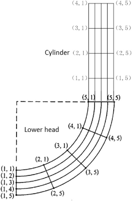
FIGURE 1. Schematic diagram of the reactor pressure vessel nodes.
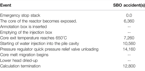
TABLE 1. Comparison of the steady-state calculation results.
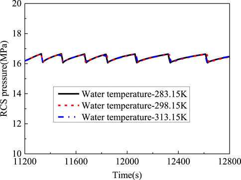
FIGURE 2. RCS pressure with different IVR water temperatures.
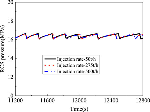
FIGURE 3. RCS pressure with different IVR injection rates.
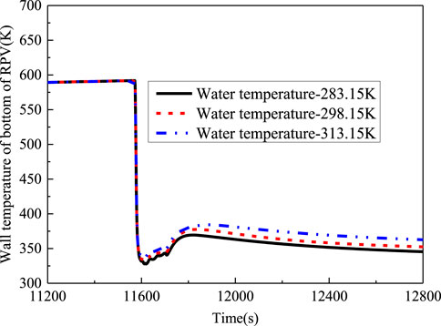
FIGURE 4. Wall temperature of the bottom of the RPV.
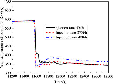
FIGURE 5. Wall temperature of the bottom of the RPV.
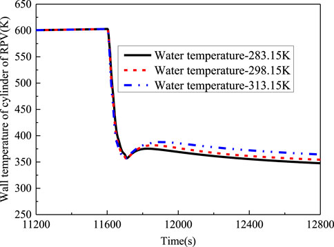
FIGURE 6. Wall temperature of the cylinder of the RPV.
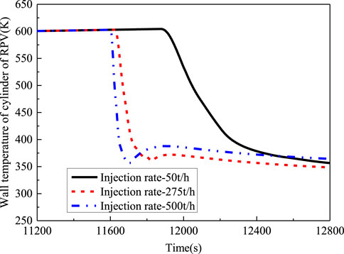
FIGURE 7. Wall temperature of the cylinder of the RPV.
Based on the above mentioned analysis, with the different water temperatures and injection flow rates, the time and degree of thermal shock experienced by the wall of the pressure vessel are obviously different. The lower the IVR water temperature and the higher the injection flow, the faster the cooling rate of the outer surface of the reactor pressure vessel is. Therefore, it can be seen that in this analysis, the thermal impact on the outer surface of the reactor pressure vessel is greater, when the IVR water temperature is 283.15 K, and the water injection rate is 500 t/h.
In the abovementioned analysis, it is known that the case with a water temperature of 283.15 K and injection rate of 500 t/h is the most ambient for the pressure vessel wall; thus, this condition was chosen for the structural integrity analysis of the pressure vessel wall. Since the IVR is put in, the outer surface is subjected to tensile stress, while the inner surface is subjected to compressive stress, and usually the value of normal stress (circumferential stress) for the axial cracks is higher, so only the axial cracks on the outer surface are considered. Since the PTS crack size is not specified in the RCC-M code, the reference available is the hypothetical crack provision in the Russian PTS analysis guidelines for the WWER reactors. According to the Russian PTS analysis guidelines, the hypothetical crack depth is 1/4 wall thickness or a smaller depth based on the NDT capability, and the ratio of crack depth to half-length a/c is 0.3–0.7. Engineering calculations show that if the hypothetical crack depth is taken as 1/4 wall thickness in the Russian PTS guidelines, the fracture mechanics analysis results of the IVR transient action will significantly exceed the code’s fracture limits. Therefore, by referring to the Russian PTS guidelines for determining the depth of smaller hypothetical cracks, the hypothetical crack situation was determined by considering the NDT method of the HPR1000 RPV cylinder and the uncertainty of the corresponding NDT method:1) axial semielliptical crack on the outer surface; 2) core cylinder and lower head area, the initial hypothetical crack depth and length are 4.5 and 27 mm, respectively; 3) based on the initial hypothetical crack, the crack size of the RPV at the end of 60a service life was obtained by the fatigue crack expansion calculation as the hypothetical crack size for PTS analysis of the HPR1000 IVR transients.
The input data involved in PTS analysis of the RPV under the late IVR injection conditions mainly include the following: transient load under normal operation and disturbance conditions, hydrostatic test load, severe temperature fluctuation, and the corresponding internal pressure load suffered by the RPV wall under the late IVR injection conditions of typical accidents. The severe temperature and pressure fluctuation data of the RPV wall after the late IVR operation of the typical SBO accident obtained by the severe accident system analysis program are shown in Figures 8–10.
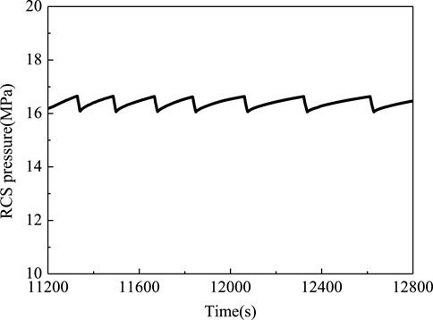
FIGURE 8. RCS pressure.
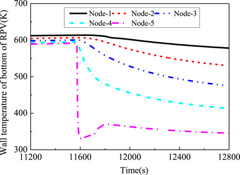
FIGURE 9. Wall temperature of the bottom of the RPV.
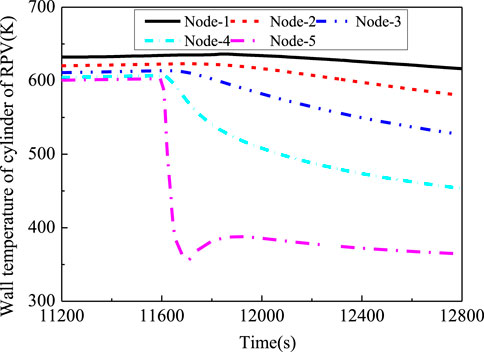
FIGURE 10. Wall temperature of the cylinder of the RPV.
Among them, the fatigue crack expansion rate parameters are adopted from the specification for the air environment. The main results of the fatigue crack expansion calculation are shown in Table 2. At the end of life, the final crack depth in the cylinder area of the reactor pressure vessel is 5.118 mm, and the final crack length is 27.478 mm. The final crack depth in the lower head area is 4.661 mm, and the final crack length is 27.122 mm. It can be clearly seen that in the whole life, the area with the larger crack depth and length of the reactor pressure vessel is the cylinder, that is, there is a great risk of failure in this area under accident conditions. Therefore, the fracture failure of the reactor pressure vessel will be evaluated based on the results of the fatigue crack growth analysis.
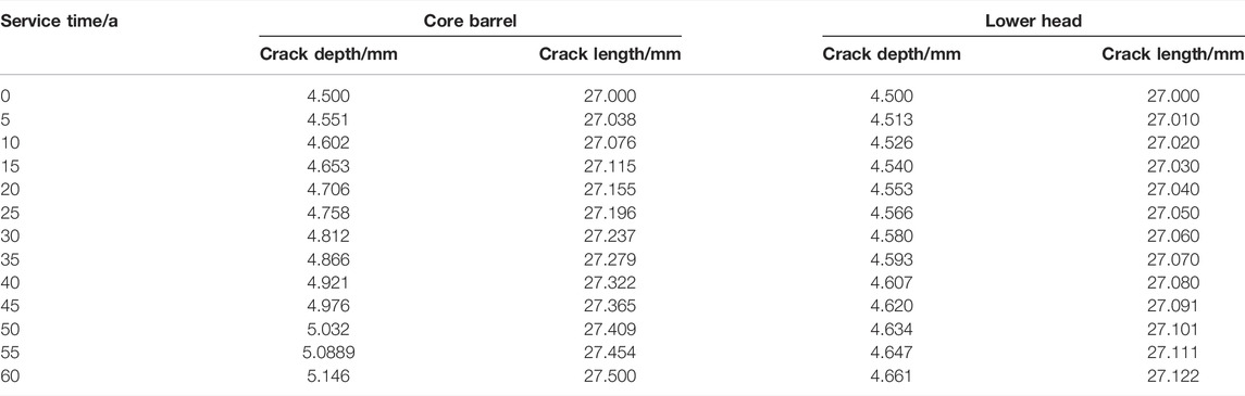
TABLE 2. Calculation results of the hypothetical crack propagation of the core barrel and lower head.
In this work, the finite element model of the lower head and cylinder of the reactor pressure vessel and the boundary conditions when the IVR is enabled are shown in Figure 11. The temperature and stress at the most dangerous time of SBO-delayed injection calculated based on the model are shown in Figure 12 and Figure 13, respectively. It can be seen that under the SBO accident, the maximum temperature of the inner wall of the reactor pressure vessel during the IVR injection is about 638.7 K, and its temperature gradually decreases from inside to outside. When the IVR is put into use, the maximum stress on the outer wall of the reactor pressure vessel is about 1.02e9 Pa, and the stress decreases gradually from outside to inside. Based on the final hypothetical crack size obtained from the fatigue crack expansion calculation and the input load, the main calculation results of the PTS strike analysis evaluation after the IVR input are shown in Table 3, according to the evaluation guidelines in Chapter 2, where the ratio of the maximum stress intensity factor correction value to the corresponding limit value is 0.874 approximately, which is at the cylinder of the reactor pressure vessel. Figures 14, 15, respectively, show the stress intensity factor evaluation results of the cylinder and lower head of the reactor pressure vessel during IVR injection. The difference between the two figures is mainly due to the inconsistent degree of the thermal shock experienced at different positions of the outer wall of the pressure vessel. The calculated stress intensity factors of the lower head and cylinder under different temperatures are lower than the limit value of the stress intensity factor. Therefore, it shows that during the SBO accident, the reactor pressure vessel can bear the pressure and resist the thermal shock without fracture failure.
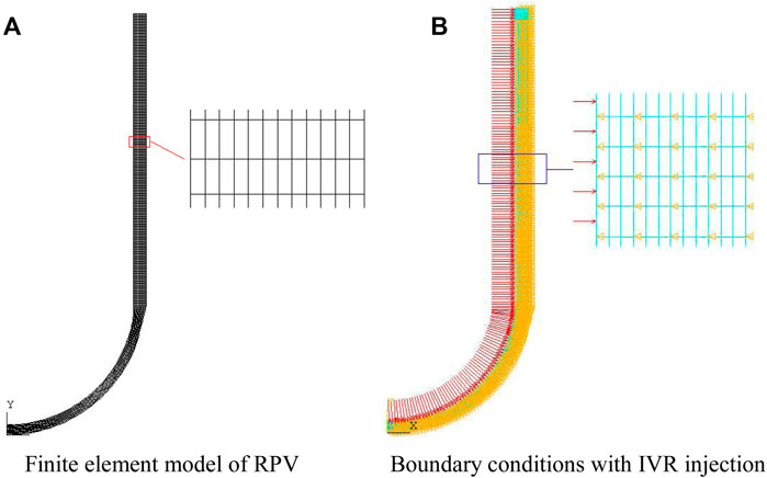
FIGURE 11. Schematic diagram of boundary conditions of the finite element model with IVR injection. (A) Finite element model of the RPV (B) Boundary conditions with the IVR injection.
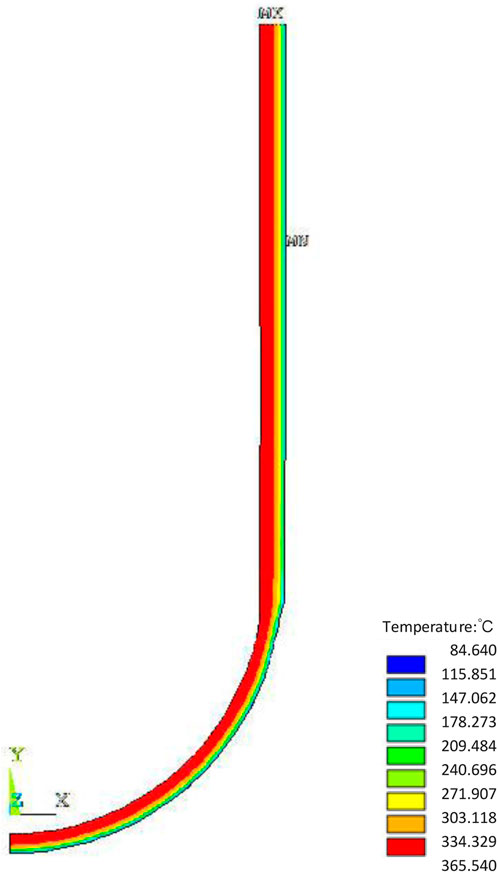
FIGURE 12. Temperature distribution at the most dangerous time of the IVR-delayed injection.
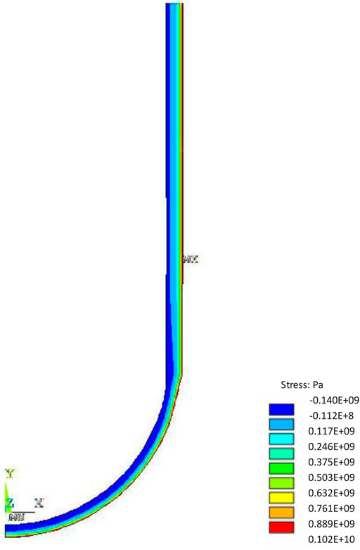
FIGURE 13. Stress distribution at the relatively most dangerous time of the IVR-delayed injection.
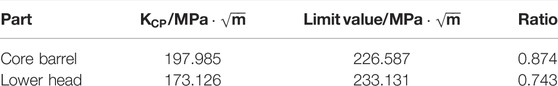
TABLE 3. Calculation results of the hypothetical crack propagation of the core barrel and lower head.
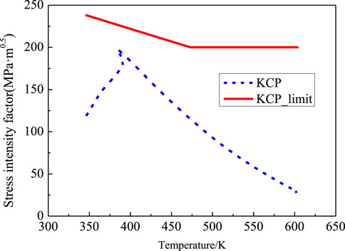
FIGURE 14. Evaluation results of the RPV cylinder under the late SBO injection condition.
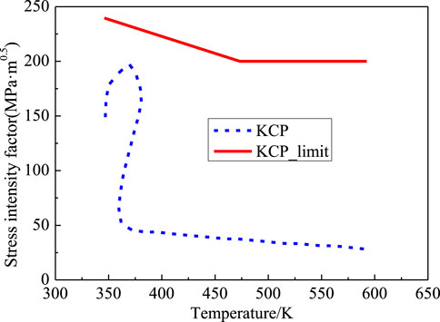
FIGURE 15. Evaluation results of the RPV lower head under the late SBO injection condition.
During the development of IVR for the HPR1000 nuclear power plant, in order to ensure the structural integrity of the RPV under the combined effect of a sudden cold shock load on the external surface and a high internal pressure load caused by IVR commissioning, the sensitivity of the two key parameters of IVR in the pressure thermal shock was analyzed. The results show that with the decrease in IVR water temperature and the increase in the injection flow rate, the more intense will be the change in the wall temperature of the reactor pressure vessel after IVR is put into operation, indicating that the thermal shock is greater. Then, based on the case with the maximum thermal impact on the wall of the reactor pressure vessel, quantitative fracture mechanics calculation and evaluation of RPV were carried out by the PTS analysis method, and the fatigue crack expansion calculations were used to obtain the fracture mechanics of the RPV core barrel and lower head area at the end of life. The results show that the area with large crack depth and length is the cylinder area of the reactor pressure vessel; in other words, there is a great risk of failure in this area under accident conditions. Based on the results of fatigue crack growth analysis, the fracture failure of the reactor pressure vessel was evaluated. The results of the PTS analysis after the IVR input are that the ratio of the maximum stress intensity factor correction value to the corresponding limit value in the RPV structure is about 0.874, which satisfies the fracture mechanics limit value of the RCC-M code. The results of the study in this work indicate that the HPR1000 RPV will not experience fracture failure when the IVR is put into operation.
The original contributions presented in the study are included in the article/Supplementary Material, further inquiries can be directed to the corresponding author.
DZ: conceptualization, software, and writing—original draft preparation. HS: methodology and data curation. BZ and TH: reviewing and editing. JD: visualization. YX: investigation and reviewing and editing. YL: supervision and project administration.
The authors appreciate the financial support from the National Key R&D Program of China (No. 2019YFB1900703).
The authors declare that the research was conducted in the absence of any commercial or financial relationships that could be construed as a potential conflict of interest.
All claims expressed in this article are solely those of the authors and do not necessarily represent those of their affiliated organizations, or those of the publisher, the editors, and the reviewers. Any product that may be evaluated in this article, or claim that may be made by its manufacturer, is not guaranteed or endorsed by the publisher.
Bass, B. R., Pugh, C. E., Sievers, J., and Schulz, H. (2001). Overview of the International Comparative Assessment Study of Pressurized Thermal-Shock in Reactor Pressure Vessels (RPV PTS ICAS). Int. J. Press. Vessel. Pip. 78 (2-3), 197–211. doi:10.1016/s0308-0161(01)00030-8
Chen, M., Lu, F., Wang, R., Huang, P., Liu, X., Zhang, G., et al. (2015). The Deterministic Structural Integrity Assessment of Reactor Pressure Vessels under Pressurized thermal Shock Loading. Nucl. Eng. Des. 288, 130–140. doi:10.1016/j.nucengdes.2015.03.008
Chen, M., Lu, F., Wang, R., and Ren, A. (2014). Structural Integrity Assessment of the Reactor Pressure Vessel under the Pressurized Thermal Shock Loading. Nucl. Eng. Des. 272, 84–91. doi:10.1016/j.nucengdes.2014.01.021
Chen, M., Qian, G., Shi, J., Wang, R., Yu, W., Lu, F., et al. (2016). Application of the French Codes to the Pressurized Thermal Shocks Assessment. Nucl. Eng. Technol. 48 (6), 1423–1432. doi:10.1016/j.net.2016.06.009
Chou, H., and Huang, C. (2014). “Structural Reliability Evaluation on the Pressurized Water Reactor Pressure Vessel under Pressurized thermal Shock Events,” in Pressure Vessels and Piping Conference, Anaheim, CA, July 20–24, 2014.
Emad, M. S., Mohamed, M. A., and Mohammed, A. (2021). A Comprehensive Review on Pressurized thermal Shock: Predictive, Preventive and Safety Issues. J. Therm. Anal. Calorim. 146, 525–544. doi:10.1007/s10973-020-10030-4
EricksonKirk, M., Chokshi, N., Woods, R., Junge, M., Malik, S., and Bessette, D. (2005). “Technical Basis for Revision of the Pressurized thermal Shock (PTS) Screening Limit in the PTS Rule (10 CFR50.61),” in 18th International Conference on Structural Mechanics in Reactor Technology, Beijing, China, August 7-12, 2005.
Faidy, C. (2011). “RCC-M, RSE-M and RCC-MRx: A Consistent Set of Mechanical Components Codes and Standards,” in Pressure Vessels and Piping Conference, Baltimore, MA, July 17–21, 2011.
Kim, J.-S., Choi, J.-B., Kim, Y.-J., and Park, Y.-W. (2003). Investigation on Constraint Effect of Reactor Pressure Vessel under Pressurized thermal Shock. Nucl. Eng. Des. 219 (3), 197–206. doi:10.1016/s0029-5493(02)00282-0
Li, F., and Modarres, M. (2005). Probabilistic Modeling for Fracture Mechanic Studies of Reactor Vessels with Characterization of Uncertainties. Nucl. Eng. Des. 235 (1), 1–19. doi:10.1016/j.nucengdes.2004.09.004
Marie, S., Ménager, Y., and Chapuliot, S. (2005). Stress Intensity Factors for Underclad and through Clad Defects in a Reactor Pressure Vessel Submitted to a Pressurised Thermal Shock. Int. J. Press. Vessel. Pip. 82 (10), 746–760. doi:10.1016/j.ijpvp.2005.06.001
Mora, D. F., Niffenegger, M., Qian, G., Jaros, M., and Niceno, B. (2019). Modelling of Reactor Pressure Vessel Subjected to Pressurized thermal Shock Using 3D-XFEM. Nucl. Eng. Des. 353, 110237. doi:10.1016/j.nucengdes.2019.110237
Pugh, C. E., Bass, B. R., and Dickson, T. L. (2007). Role of Probabilistic Analysis in Integrity Assessments of Reactor Pressure Vessels Exposed to Pressurized Thermal-Shock Conditions. Eng. Fail. Anal. 14 (3), 501–517. doi:10.1016/j.engfailanal.2005.08.006
Server, W. L., and Nanstad, R. K. (2015). 6-Integrity and Embrittlement Management of Reactor Pressure vessels(RPVs) in Light-Water Reactors. Cambridge: Woodhead Publishing Series in Energy, 132–155. doi:10.1533/9780857096470.2.132
Stahlkopf, K. E. (1984). Pressure Vessel Integrity under Pressurized Thermal Shock Conditions. Nucl. Eng. Des. 80, 171–180. doi:10.1016/0029-5493(84)90165-1
Sun, X., Chai, G., and Bao, Y. (2017). Elastic and Elastoplastic Fracture Analysis of a Reactor Pressure Vessel under Pressurized thermal Shock Loading. Eur. J. Mech. - A/Solids 66, 69–78. doi:10.1016/j.euromechsol.2017.06.008
Thamaraiselvi, K., and Vishnuvardhan, S. (2020). Fracture Studies on Reactor Pressure Vessel Subjected to Pressurised thermal Shock: A Review. Nucl. Eng. Des. 360, 110471. doi:10.1016/j.nucengdes.2019.110471
Wang, M., Bai, L., Wang, L., Qiu, S., Tian, W., and Su, G. H. (2017). Thermal Hydraulic and Stress Coupling Analysis for AP1000 Pressurized thermal Shock (PTS) Study under SBLOCA Scenario. Appl. Therm. Eng. 122, 158–170. doi:10.1016/j.applthermaleng.2017.04.106
Keywords: in-vessel retention system, pressure vessel, pressurized thermal shock, fracture mechanics, advanced PWR
Citation: Zhu D, Sun H, Zheng B, Huang T, Deng J, Xu Y and Luo Y (2022) Study on Thermal Shock Failure Characteristics of RPV During IVR System Start-Up for Typical Advanced PWR. Front. Energy Res. 10:899405. doi: 10.3389/fenrg.2022.899405
Received: 18 March 2022; Accepted: 11 April 2022;
Published: 30 May 2022.
Edited by:
Yapei Zhang, Xi’an Jiaotong University, ChinaReviewed by:
Yandong Hou, Northeast Electric Power University, ChinaCopyright © 2022 Zhu, Sun, Zheng, Huang, Deng, Xu and Luo. This is an open-access article distributed under the terms of the Creative Commons Attribution License (CC BY). The use, distribution or reproduction in other forums is permitted, provided the original author(s) and the copyright owner(s) are credited and that the original publication in this journal is cited, in accordance with accepted academic practice. No use, distribution or reproduction is permitted which does not comply with these terms.
*Correspondence: Dahuan Zhu, ZGFodWFuX3podUBzaW5hLmNvbQ==; Jian Deng, ZGVuZ2ppYW5fbnBpY0AxNjMuY29t
Disclaimer: All claims expressed in this article are solely those of the authors and do not necessarily represent those of their affiliated organizations, or those of the publisher, the editors and the reviewers. Any product that may be evaluated in this article or claim that may be made by its manufacturer is not guaranteed or endorsed by the publisher.
Research integrity at Frontiers
Learn more about the work of our research integrity team to safeguard the quality of each article we publish.