 Yongcheng Du
 Shiyao Wang3
- 1Institute of Noise and vibration, Naval University of Engineering, Wuhan, China
- 2National Key Laboratory on Ship Vibration and Noise, Wuhan, China
- 3Department of Power Engineering, Naval University of Engineering, Wuhan, China
- 4Teaching and Research Support Center, Naval University of Engineering, Wuhan, China
The heat and mass transfer process of the laminar falling liquid film along a vertical heated plate with constant heat flux is studied. Through thermal equilibrium analysis, the energy conservation equation is established and solved by the parametric variation method. The analytical solution considering evaporation is in good agreement with the experimental results. Based on the model, the temperature distribution of liquid film with or without evaporation is obtained. It is demonstrated that the thickness and average temperature of liquid film show decreasing and increasing trends linearly in the flow direction. Along with the increase in the evaporation rate, the average temperature decreases and the share of evaporative heat dissipation in the total heat flux increases, which demonstrates that evaporation is an important physical factor for heat dissipation when the falling liquid film flows on a hot plate.
Introduction
Vertical falling film heat dissipation refers to the process in which the film flows from top to bottom under the action of gravity, viscous shear, and wall adhesion, and the heat is transferred from the wall to the film and accompanied by evaporation. It is widely used as an enhanced cooling method in the fields of chemical process, nuclear reactor safety, and fire protection engineering (Yang and Yuen, 2018; Turkyilmazoglu, 2021; Choi and Cho, 2022). In particular, the mixed ferromagnetic nanofluid film and microchannel fluid film show a good application prospect for heat transfer (Tlili et al., 2020; Tlili et al., 2022). For large military platforms, the falling film can be used to reduce the infrared contrast between the warm vertical wall surface and the environment (Peng et al., 2012a; Peng et al., 2012b). In the present work, the authors mainly discuss the related heat and mass transfer problems in the application of liquid film to control or balance the temperature of the large vertical wall to reach or approach that of the background environment.
In recent years, many researchers have studied the flow and heat transfer process of the falling film under different conditions by theoretical, numerical, and experimental methods (Nasr et al., 2017; Malika et al., 2017; Turkyilmazoglu, 2021; Yue et al., 2021). Because of the complexity of the problem, numerical and experimental studies tend to prevail. However, analytical solutions play an irreplaceable role in universality. The following findings are of great significance. Nusselt (1916) made basic research on this topic and gave a series of equations describing the velocity and thickness distribution of the film. Saouli and Aïboud-Saouli (2004) established a theoretical model of laminar flow falling film along an inclined plate by ignoring the inlet effect and gained the velocity and temperature distributions by separating variables. Peng et al. (2012a) and Peng et al. (2012b) derived the solution of liquid film energy equation with constant wall temperature and heat flux using the integral analysis method. Meyer (2014) and Meyer (2015) introduced Laplace transform to solve the problem with constant film velocity for an isothermal or adiabatic wall boundary condition. Gu et al. (2018) analytically treated the energy and absorbate equations of the liquid film by means of integral transforms and obtained the exact series solutions for temperature and mass fraction fields under the assumptions of both the insulated and isothermal wall boundary conditions.
Another problem is the effect of evaporation on falling film heat transfer. According to the best knowledge of the authors, some scholars in this field have not considered the evaporation effect in the study of the above physical processes, which may be a factor that cannot be ignored. In a few relevant studies, the evaporation of binary liquid film was numerically analyzed by Nasr et al. (2011). Assad and Lampnen (2002), Leu et al. (2006), and Leu et al. (2009) established a mathematical model for the evaporation process on a constant temperature vertical plate between liquid film and wall surface. Cherif et al. (2010) conducted experimental studies on natural and forced convection, studying the evaporation of thin liquid films falling on the inner surface of plates in vertical channels. In addition, some studies on film flow have been based on constant film thickness (He et al., 1998; Song et al., 1999; Wang et al., 2000; Cherif et al., 2010; Nasr et al., 2011), which simplifies the problem but deviates from the physical facts to some extent.
Based on the above situation, the purpose of this work is to study the heat and mass transfer process of falling film, considering the change of water evaporation and film thickness, to determine the temperature distribution of the film under constant heat flux boundary conditions. In particular, the effect of film evaporation rate on heat transfer will be analyzed. In terms of application background, as mentioned above, the research results of this study will serve to eliminate infrared contrast between target and background, but this is not the content of this study.
Mathematical formulation
The physical model for a laminar falling liquid film due to gravity along a vertical plate is illustrated in Figure 1. The plate is subjected to a uniformed heat flux
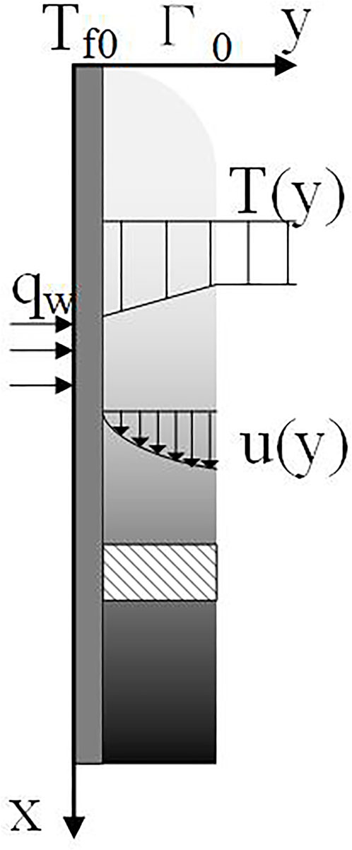
FIGURE 1. Physical model of flowing liquid film.
Assumptions
For the mathematical formulation of the problem, the flowing simplified assumptions should be considered:
1. The flow is two dimensional and steady state with constant thermal-physical properties because the temperature range is not very large.
2. The flow is laminar, and the surface of the liquid film is non-oscillatory. This assumption is reasonable by virtue of the low velocities associated with the film.
3. The inertial force between liquid film and air is ignored because of the stillness of the air and the low speed of the liquid film.
4. The heat is transferred across the film by conduction only due to the laminar flow.
Liquid film flow model
According to the above assumptions and Figure 1, the Navier–Stokes equations describing the laminar falling film can be reduced to (Nusselt, 1916; Yang and Yuen, 2018):
where
The momentum equation adopts the boundary conditions of no slip-on wall surface and no stress on film surface according to the assumptions mentioned above:
where Δ is the thickness of the liquid film.
Combining Eqs 1–3, the velocity
where
Energy conservation equation with evaporation considered
Considering the limit layer approximation, the energy equation is
where
The total heat load
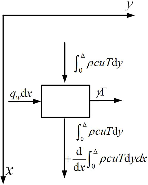
FIGURE 2. Energy conservation model of flowing liquid film.
Eq. 9 can be simplified by removing the second term on the left and the first term on the right:
where
By substituting Eqs 6, 11 into Eq. 10, the first and second terms on the right side of Eq. 10 may be derived as the function of
Therefore, Eq. 10 can be written as
Furthermore, Eq. 14 is rearranged as
with the boundary conditions:
Here, the evaporation rate of the liquid film is supposed to be uniform. Therefore, the thickness reduction of the liquid film is proportional to the flowing distance x. Eq. 15 is a nonhomogeneous linear differential equation and can be solved by utilizing the parametric variation method:
For the fully developed region of the liquid film with constant heat flux boundary conditions, there is a relationship of
The boundary conditions of Eq. 18 are
By integrating Y in Eq. 18 and using boundary conditions (Eq. 19, Eq. 20), it can be obtained:
Then, the relationship between bulk and wall temperature is yielded based on Eqs. 4, 21:
In addition, the other form of temperature distribution is gained by substituting Eq. 22 into Eq. 21:
in which
Energy conservation equation without evaporation considered
For the case without considering the evaporation process, the liquid film thickness remains unchanged, which indicates that the evaporation rate
Furthermore, Eq. 23 is reduced with Eqs 24, 25 into
which describes the temperature distribution of liquid film without evaporation considered.
Evaporation rate of liquid film
As we know, there exists an analogy between mass transfer and heat transfer (Incropera et al., 1996):
where
Expanding the four dimensionless numbers in Eq. 27, the following relationship can be obtained
where
The evaporation quality of the liquid film is
where
Supposing the thickness reduction of the liquid film is proportional to the flowing distance x,
By substituting Eq. 28 into Eq. 30, the evaporation rate of the liquid film is
Convection heat transfer coefficient between liquid film and wall
The heat transfer coefficient is defined as
If the evaporation effect were not considered,
Therefore, the convection heat transfer coefficient without evaporation considered is
If the evaporation effect were considered, the convection heat transfer coefficient
where
Results and discussion
In order to verify the validity, the analytical solutions with and without evaporation were compared with the experimental data of Wang et al. (2000) in Table 1. Tin in Table 1 represents the inlet temperature. Exp-Tout, Evap-Tout, and Non-evap-Tout represent the outlet temperature of in reference experiment, evaporation solution, and non-evaporation solution, respectively. The errors in Table 1 represent the relative deviation of outlet temperature between the evaporation solution and the experiment.

TABLE 1. Comparison of Tout under different conditions.
Table 1 shows that the evaporation solutions established in this article are in good agreement with the experimental values, and the error values are all less than 10%. This emphasizes that, in the field of this study, the evaporative heat transfer of liquid film cannot be ignored unless the requirements for solving accuracy are relaxed.
The model results are compared with the experiment in the data graph form, as shown in Figures 3, 4. These two graphs represent the relationship between Tout and qw. When Tin is almost the same, the outlet temperature Evap-Tout of evaporation solution has a good consistency with Exp-Tout of the experiment, whereas the Non-evap-Tout of the non-evaporation solution has a relatively poor consistency with experiment. In detail, the outlet temperature got by the analytical solution increases strictly linearly with the heat load, whereas that got by the experiment shows an approximate trend like the former. This phenomenon is easy to understand because there are always some measurement errors in the test. For example, in Figure 4, in the two experimental cases with the same inlet temperature of 18.1°C and different heat loads of 20,800 and 21,480 W/m2, the seemingly contradictory outlet temperature intensity is shown, which is 23°C and 22.9°C, respectively.
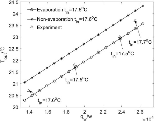
FIGURE 3. Comparisons of Tout with Exp. data under Tin = 17.6°C.
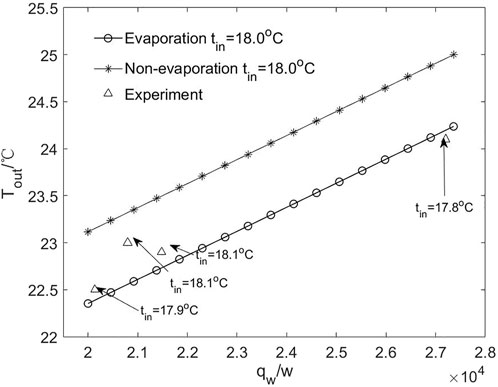
FIGURE 4. Comparisons of Tout with Exp. data under Tin = 18.0°C.
For the application of falling liquid film presented in this article, the heat flux loaded onto the film is set at 20,000 w/m2, and the mass flow rate is 0.3 kg m−1 s−1. Under the same initial and boundary conditions, the final falling film depth will depend on the evaporation rate. By calculating Eq. 31, the evaporation rate dΔ/dx of the liquid film with different air heat transfer coefficients can be obtained. When the values of heat transfer coefficients are 0, 8, 12, and 20 W/(m2°C), dΔ/dx are 0, −3.88e-7, −5.82e-7, and −9.70e-7, respectively. Figure 5 shows that the thickness of liquid film decreases with the increase in x. This figure shows that if the evaporation were not considered, the thickness of the falling film would keep the same; otherwise, that will decrease along with the flow distance. Note that the existence of evaporation does not change the thickness of the liquid film a lot, approximately 0.03%–0.04%.
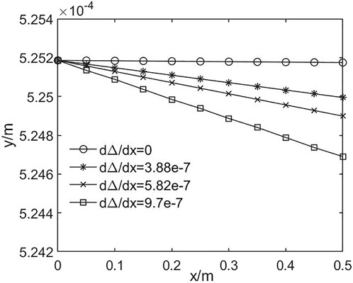
FIGURE 5. Thickness of liquid film under different hair.
Figure 6 shows the bulk temperature of the liquid film with different dΔ/dx. Along with the flow distance of film, the bulk temperature increases linearly for both evaporation and non-evaporation solutions. Nevertheless, the temperature decreases rapidly with the increase in dΔ/dx. At the outlet, the temperature with dΔ/dx = 9.7e-7 is 26.03°C, about 2°C less than that of the non-evaporation solution. This confirms the general notion that heat transfer is more efficient in the presence of phase transitions.
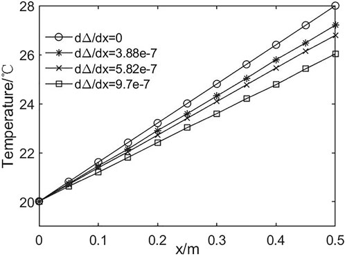
FIGURE 6. Bulk temperature of the liquid film under different dΔ/dx.
Eq. 10 represents the dissipation of wall energy. For the two terms on the right, the first represents the energy taken away by the flow of the liquid film, and the second term represents that by evaporation. Figure 7 shows the relationship between the percentage of energy carried by evaporation and the evaporation rate (dΔ/dx). This figure shows that the share of evaporation energy increases with the increase in dΔ/dx. When the natural convection heat transfer coefficient is 12W/(m2°C), dΔ/dx is −5.82e-7, and the evaporation rate accounts for 14.7% of the total energy.
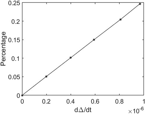
FIGURE 7. The evaporation percentage of total energy under different dΔ/dx.
Conclusion
The energy conservation equation of falling liquid film is established by thermal equilibrium analysis, and the analytical solutions with and without evaporation effect considered are obtained by means of parameter variational and integral methods. The validity of the analytical solution is verified by comparing it with the experimental data. It is proved that the evaporative heat transfer of the liquid film cannot be ignored unless the requirement of solving precision is relaxed.
In order to obtain the analytical solution, the physical problem is simplified appropriately. For example, the flow is assumed to be laminar flow and is quasi-two-dimensional. Fully turbulent flow and three-dimensional problems will be considered in future studies. In addition, this study applies to the case where there is no liquid film boiling. Therefore, in subsequent studies, the problem of high heat flux needs to be focused.
Data availability statement
The original contributions presented in the study are included in the article/supplementary material. Further inquiries can be directed to the corresponding author.
Author contributions
All authors listed have made a substantial, direct, and intellectual contribution to the work and approved it for publication.
Funding
This study was funded by the National Natural Science Foundation of China (11504426) and the Independent Research Projects of Naval University of Engineering (No.20190008).
Conflict of interest
The authors declare that the research was conducted in the absence of any commercial or financial relationships that could be construed as a potential conflict of interest.
Publisher’s note
All claims expressed in this article are solely those of the authors and do not necessarily represent those of their affiliated organizations or those of the publisher, the editors, and the reviewers. Any product that may be evaluated in this article, or claim that may be made by its manufacturer, is not guaranteed or endorsed by the publisher.
References
Assad, M. H., and Lampnen, M. J. (2002). Mathematical modeling of falling liquid film evaporation process. Int. J. Refrig. 25, 985–991. doi:10.1016/s0140-7007(01)00064-0
Cherif, A. S., Jabrallah, S. B., Corriou, J. P., and Belghith, A. (2010). Intensification of the liquid film evaporation in a vertical channel. Desalination 250, 433–437. doi:10.1016/j.desal.2009.09.071
Choi, C. -J., and Cho, H. K. (2022). Numerical investigations of liquid film offtake by transverse gas flow in a downcomer annulus geometry. Front. Energy Res. 10, 847458. doi:10.3389/fenrg.2022.847458
Gu, L. D., Min, J. C., and Tang, Y. C. (2018). Effects of mass transfer on heat and mass transfer characteristics between water surface and airstream. Int. J. Heat Mass Transf. 122, 1093–1102. doi:10.1016/j.ijheatmasstransfer.2018.02.061
He, S., An, P., Li, J., and Jackson, J. (1998). Combined heat and mass transfer in a uniformly heated vertical tube with water film cooling. Int. J. Heat Fluid Flow 19, 401–417. doi:10.1016/s0142-727x(98)10021-8
Incropera, F. P., DeWitt, D. P., and Bergman, T. L. (1996). Fundamentals of heat and mass transfer. New York: John Wiley & Sons.
Leu, J., Jang, J., and Chou, Y. (2006). Heat and mass transfer for liquid film evaporation along a vertical plate covered with a thin porous layer. Int. J. Heat Mass Transf. 49, 1937–1945. doi:10.1016/j.ijheatmasstransfer.2005.11.004
Leu, J. S., Jang, J. Y., and Chou, W. C. (2009). Convection heat and mass transfer along a vertical heated plate with film evaporation in a non-Darcian porous medium. Int. J. Heat Mass Transf. 52, 5447–5450. doi:10.1016/j.ijheatmasstransfer.2009.06.033
Malika, I., Malek, T. B., Aberkane, S., Mouderes, M., Spitem, P., and Ghezal, A. (2017). Analytical and numerical study of the evaporation on mixed convection in vertical rectangular cavity. Fluid Dyn. Material Process 13 (2), 85–105. doi:10.3970/fdmp.2017.013.085
Meyer, T. (2015). Analytical solution for combined heat and mass transfer in laminar falling film absorption with uniform film velocity - diabatic wall boundary. Int. J. Heat Mass Transf. 80, 802–811. doi:10.1016/j.ijheatmasstransfer.2014.09.049
Meyer, T. (2014). Analytical solution for combined heat and mass transfer in laminar falling film absorption with uniform film velocity – isothermal and adiabatic wall. Int. J. Refrig. 48, 74–86. doi:10.1016/j.ijrefrig.2014.08.005
Nasr, A., Al-Ghamdi, A. S., Feddaoui, M’barek., Alsoufi, M. S., and Ben Nasrallah, S. (2017). Numerical study of falling binary liquid film evaporation: Liquid film thickness. Desalination Water Treat. 74, 35–43. doi:10.5004/dwt.2017.20606
Nasr, A., Debbissi Hfaiedh, C., and Ben Nasrallah, S. (2011). Numerical study of evaporation by mixed convection of a binary liquid film. Energy 36, 2316–2327. doi:10.1016/j.energy.2011.02.039
Nusselt, W. (1916). Die Oberflächenkondensation des Wasserdampfes. Z. Ver. Deutch. Ing. 60, 541–546.
Peng, Y. S., Yang, L., and Du, Y. C. (2012). Integral analysis of heat transfer on falling laminar liquid Film with constant heat flux. Adv. Mat. Res. 516-517, 30–35. doi:10.4028/www.scientific.net/amr.516-517.30
Peng, Y. S., Yang, L., and Du, Y. C. (2012). Study on application of subcooling films in temperature field and infrared stealth technology. Infrared Laser Eng. (China) 41 (10), 2572–2577.
Saouli, S., and Aïboud-Saouli, S. (2004). Second law analysis of laminar falling liquid film along an inclined heated plate. Int. Commun. Heat Mass Transf. 31 (6), 879–886. doi:10.1016/s0735-1933(04)00074-0
Song, B., Inaba, H., Horibe, A., and Ozaki, K. (1999). Heat, mass and momentum transfer of a water film flowing down a tilted plate exposed to solar irradiation. Rev. Gen. Therm. 38, 384–397. doi:10.1016/s0035-3159(99)80028-2
Tlili, I., Mustafa, M. T., Kumar, K. A., and Sandeep, N. (2020). Effect of asymmetrical heat rise/fall on the film flow of magnetohydrodynamic hybrid ferrofluid. Sci. Rep. 10, 6677. doi:10.1038/s41598-020-63708-y
Tlili, I., Sajadi, S. M., Baleanu, D., and Ghaemi, F. (2022). Flat sheet direct contact membrane distillation study to decrease the energy demand for solar desalination purposes. Sustain. Energy Technol. Assessments 52, 102100. doi:10.1016/j.seta.2022.102100
Turkyilmazoglu, M. (2021). Heat absorption due to falling film with imposed uniform mass fraction at the wall. Int. J. Heat Mass Transf. 177, 121585. doi:10.1016/j.ijheatmasstransfer.2021.121585
Wang, B. X., Zhang, J. T., and Peng, X. F. (2000). Experimental study on the dryout heat flux of falling liquid film. Int. J. Heat Mass Transf. 43, 1897–1903. doi:10.1016/s0017-9310(99)00279-3
Yang, J. C., and Yuen, W. W. (2018). Heat transfer in a falling laminar liquid film with in-depth radiation absorption. Int. Commun. Heat Mass Transf. 94, 47–52. doi:10.1016/j.icheatmasstransfer.2018.03.009
Yue, Y., Yang, J., Li, X., Song, Y., Zhang, Y., and Zhang, Z. (2021). Experimental research on falling film flow and heat transfer characteristics outside the vertical tube. Appl. Therm. Eng. 199, 117592. doi:10.1016/j.applthermaleng.2021.117592
Nomenclature
Abbreviations
Greek symbols
Subscripts
Keywords: liquid film, evaporation, heat and mass transfer, laminar flow, analytical solution
Citation: Du Y, Wang S, Li D, Peng Y and Yang L (2022) Effect of evaporation rate for the heat and mass transfer of the laminar liquid falling film in still air. Front. Energy Res. 10:899023. doi: 10.3389/fenrg.2022.899023
Received: 18 March 2022; Accepted: 27 July 2022;
Published: 30 August 2022.
Edited by:
Kim Choon Ng, King Abdullah University of Science and Technology, Saudi ArabiaCopyright © 2022 Du, Wang, Li, Peng and Yang. This is an open-access article distributed under the terms of the Creative Commons Attribution License (CC BY). The use, distribution or reproduction in other forums is permitted, provided the original author(s) and the copyright owner(s) are credited and that the original publication in this journal is cited, in accordance with accepted academic practice. No use, distribution or reproduction is permitted which does not comply with these terms.
*Correspondence: Yongcheng Du, ZHljaGVuZ0B5ZWFoLm5ldA==