 Yang Hu
 Lehua Liang
 Lekang Chen
 Wenjie Zeng
94% of researchers rate our articles as excellent or good
Learn more about the work of our research integrity team to safeguard the quality of each article we publish.
Find out more
ORIGINAL RESEARCH article
Front. Energy Res., 25 August 2022
Sec. Nuclear Energy
Volume 10 - 2022 | https://doi.org/10.3389/fenrg.2022.893528
This article is part of the Research TopicDynamics and Control for Nuclear EnergyView all 8 articles
To study the model predictive control (MPC) for a lead-cooled fast reactor's core power control system (LFR), firstly, the LFR core is established with the state space model. Then, to establish an LFR core power control system, a predictive model controller is used. Finally, the conditions of 20pcm step reactivity and 5% step down of coolant inlet temperature are introduced to study the control characteristic. The maximum overshot (MO) and the transient time are calculated in the time domain, and the stability of the core power control system is analyzed using the Nyquist and Bode diagrams in frequency domains. The result shows that the MPC controller and PID controller are feasible in core power control, and the core power control systems are closed-loop stable systems.
Lead-cooled fast reactors (LFRs), one of the candidate reactor types in the fourth generation of nuclear power systems that show the most potential, are under investigation for their high security and easy miniaturization. LFRs use liquid lead or lead alloy with a high boiling point and high thermal conductivity as a coolant, which not only has a hard neutron energy spectrum but also effectively improves the reactor's safety limit and operation range (Xiuzhong, 2002). Therefore, LFR has a good neutron economy and safety (Lorenzi et al., 2013).
The fast reactor has a small delayed neutron share, short prompt neutron lifetime, and weak Doppler effect. Under reactivity disturbance, the reactor power changes rapidly because of poor self-balancing ability. Therefore, the fast reactor controller requires a more rapid response speed and higher control accuracy. Linear Active Disturbance Rejection Control with and without model information has been established to meet this demand. Both have fast regulation speed and accuracy for the power control system of LFR (Shen, 2019). To resist external interference and parameter uncertainty, a synovial control method based on robust nonlinear control was established (Ansarifar et al., 2016). While some tracking controllers use only the current tracking command, the predictive model controllers can achieve better tracking performance because future commands are considered in addition to the current tracking command (Na et al., 2005). Based on the advantages of MPC, a predictive model controller for the load-following operation of a pressurized water reactor was designed. The controller was approved using the three-dimensional nuclear reactor analysis code master developed by Korea Atomic Energy Research Institute (Na et al., 2005). A nonlinear model predictive controller for variable load process of High-Temperature Gas-cooled was established, which overcomes the problems of system coupling, nonlinearity, and time-varying parameters of new nuclear power plant HTR-PM (Song, 2012). The core power control of a fast reactor cannot be satisfied by a traditional PID controller. Traditional PID controllers cannot fulfill the core power control of a fast reactor. In this work, the advanced control strategy predictive model control was used to design the controller to study the core power control of a fast reactor. The advantage of the MPC controller lies in its good tracking performance and rolling optimization characteristics.
The remaining parts of thisarticle are organized in the following sequence. In section 2, the linear system model of LFR is established by the lumped parameter method, and the simulation system based on the state space model is designed. Section 3 introduces the core power control system with an MPC controller for LFR. Section 4 shows a simulated response of the core power control system under reactivity insertion accident and coolant inlet temperature disturbance, and the Nyquist and Bode diagram are drawn. Finally, section 5 has our conclusions.
Based on the point reactor neutron dynamics with six groups of effective delayed neutron and thermal-hydraulic coupling methods, taking into account the reactivity feedback caused by the temperature change of core coolant, fuel, and cladding, the ordinary differential equations are shown in Eq. 1 to describe the nonlinear model of LFR core (Lorenzi et al., 2013).
where the relationship between relative core power and relative neutron density should conform to Eq. 2.
The linear model is established based on the nonlinear reactor core model by introducing small perturbations and ignoring the high-order term (Li and Zhao, 2013; Yinuo, 2021). The ordinary differential equations are shown in Eq. 3
Following Eq. 3, the state space model of the reactor core is obtained as Eq. 4.
where u =
Model predictive control (MPC), also known as receding horizon control, has gained attention in academia and industry due to its ability to optimally control nonlinear systems subject to physical constraints (Brian Froisy, 1994; Mayne, 2000; Hu and Ding, 2019). The structure of the MPC controller is shown in Figure 1.
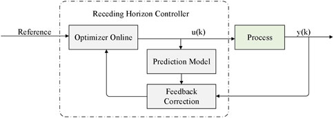
FIGURE 1. Schematic block diagram of the MPC controller.
The output of predictive model control depends not only on the input and output of the control system but also on the control variables of the controller output. The essence of model prediction is to establish the relationship between historical output and the future output of the control system (Na et al., 2005; Chen, 2013).
(1) Ignoring the input measurable interference to simplify the model, the discrete-time state-space model incremental formula is introduced:
where A, B, C, and D are paraments of the MPC controller, x is the internal variable, u is the control variable, and y is the control system’s output
(2) Based on the discrete-time state space model, we set p as the prediction time and m as the control time, then at the time p:
(3) Predicted output of the reactor core power control system in the next p
where
Based on the model prediction, the most important feature of MPC is rolling optimization, which repeatedly solves the performance index J online
Based on model prediction and receding horizon control, to prevent decreasing adaptability of the MPC to the controlled object under external interference, the model predictive output is further modified to be the input of receding horizon control, forming a closed-loop control system.
As shown in Figure 2, the I/V converter converts reactor core power into voltage signal V(n) to be the feedback signal of the core power control system with the MPC controller, and the MPC controller regulates the electrical signal and outputs to the control rod drive mechanism. The control rod drive mechanism drives the control rod to move in the reactor according to the relative power deviation. Inserting or withdrawing reactivity in the reactor adjusts the reactor power back to the setting value and finally makes the core power stable (Hu, 2021; Yinuo, 2021). As shown in Figure 3, based on the operation strategy of stable core power with MPC controller, the core power control simulation system with MPC controller is designed by using the MPC design module of MATLAB/Simulink, taking 0.1s as the sample time. The V(n) of the core power system is the Y and the ΔV1 is Δu of the MPC controller.
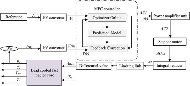
FIGURE 2. LFR core power control system with MPC controller.
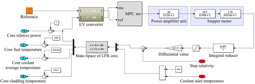
FIGURE 3. Core power control system with MPC controller of LFR.
To compare the control characteristic of the MPC controller and PID controller, firstly, we set the parameters of the PID controller by a trial-and-error method. The parameters Kp, Ki, and Kd of the controller are 0.067, 0.0123, and 0.0006 through the continuous test. Then 20pcm step reactivity and the 5% step down of coolant inlet temperature are carried out. To compare the dynamic characteristics of a reactor core power control system with MPC and PID controller, the maximum overshot (MO) and the transient time are calculated in the time domain. The Nyquist and Bode diagram are drawn in a frequency domain to analyze their stability.
At 100%FP, the response of the LFR core under the power control system with 20 pcm step reactivity is shown in Figure 4. Figure 5 shows the response of the LFR core power control system under the 5% step down of coolant inlet temperature. With the MPC controller or the PID controller, relative core power, core fuel temperature, core coolant average temperature, and core-cladding temperature finally return to the initial level, introducing step reactivity. In Figures 4, 5, although both have great control characteristics, the dynamic characteristics of the core power control system with MPC controller are better than the PID controller in terms of MO and transient time.
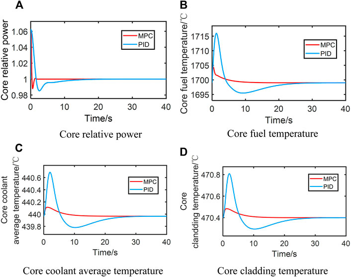
FIGURE 4. Response of an LFR core power control system after introducing 20 pcm step reactivity.
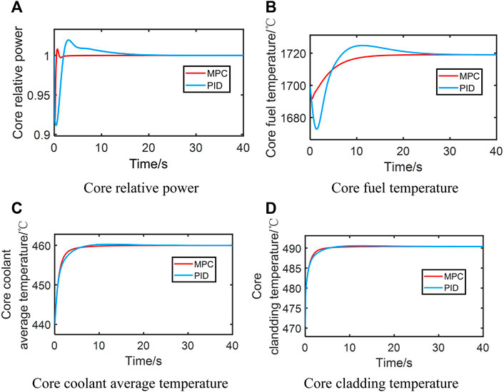
FIGURE 5. Response of an LFR core power control system after introducing a 5% step down of core coolant inlet temperature.
In the frequency domain, the core power control system is linearized using the APP linearize model in MATLAB/Simulink, and the Nyquist diagram, Pole-Zero Map , and Bode diagram are drawn. As shown in Figures 6, 7, the Nyquist diagram and Pole-Zero Map are drawn to judge the absolute stability of the core power control system. According to the Nyquist diagram, the number of times that the Nyquist curve bypasses point (−1,0) counterclockwise is zero, and the number of characteristic roots outside the unit circle is zero. According to the Nyquist criterion, both closed-loop systems are stable. And as shown in Figure 8, the Bode diagram is drawn to compare the relative stability of different core power control systems. It can be seen from the Bode diagram that both phase margin and gain margin are stable in the low-frequency region.
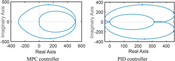
FIGURE 6. Nyquist diagram of the core power control system.
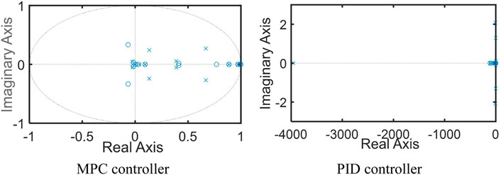
FIGURE 7. Pole-Zero map of the core power control system. Note: MPC controller is indicated in the blue line, and PID controller is shown in the red line.
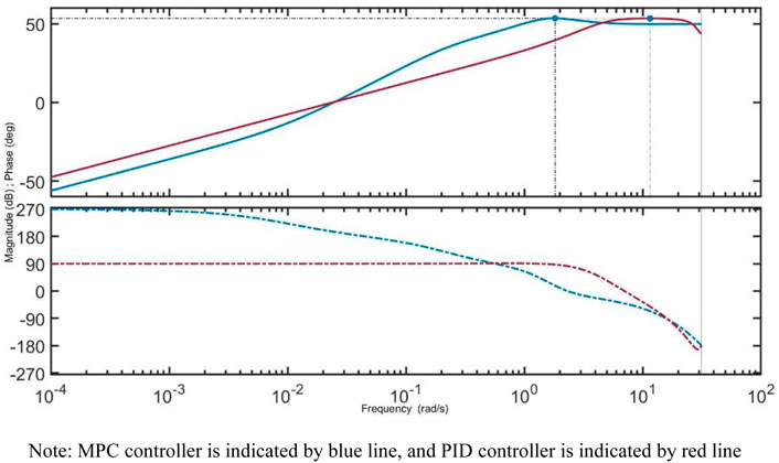
FIGURE 8. Bode diagram of a core power control system with MPC and PID controller.
The core power control system of the lead-cooled fast reactor is designed with the predictive model controller. According to the point reactor dynamics, the state space model of LFR is established using the perturbation theory. The core power control systems with MPC controller and PID controller are designed under the operation strategy of stable core power. We found that the control characteristic of the core power control system with MPC controller is better than the core power control system with PID controller. Both core power control systems with MPC controller and PID controller are stable. The concept of a core power system with an MPC controller and its control characteristic and stability of it is given in this research and can provide theoretical references for engineering applications.
The original contributions presented in the study are included in the article/Supplementary Materials, and further inquiries can be directed to the corresponding author.
YH: experimental data analysis, writing—original draft. LL: visualization, investigation. LC: project review. WZ: supervision, writing—review and editing.
The work was partly supported by the Provincial Innovation and Entrepreneurship Training Program for Undergraduates (S202210555135, S202210555133).
The authors declare that the research was conducted without any commercial or financial relationships that could be interpreted as a potential conflict of interest.
All claims expressed in this article are solely those of the authors and do not necessarily represent those of their affiliated organizations or those of the publisher, the editors, and the reviewers. Any product that may be evaluated in this article, or claim that may be made by its manufacturer, is not guaranteed or endorsed by the publisher.
Ansarifar, G. R., Nasrabadi, M., and Hassanvand, R. (2016). Core Power Control of the Fast Nuclear Reactors with Estimation of the Delayed Neutron Precursor Density Using Sliding Mode Method. Nucl. Eng. Des. 296, 1–8. doi:10.1016/j.nucengdes.2015.10.015
Brian Froisy, J. (1994). Model Predictive Control: Past, Present and Future. ISA T 33, 235–243. doi:10.1016/0019-0578(94)90095-7
Hu, J., and Ding, B. (2019). Output Feedback Robust MPC for Linear Systems with Norm-Bounded Model Uncertainty and Disturbance. Automatica 108, 108489. doi:10.1016/j.automatica.2019.07.002
Hu, Y. (2021). Modelling and Simulation of the Primary System for a Small Lead-Cooled Fast Reactor with a Ratio of Core Power to Flow. Ann. Nucl. Energy 2022, 167. doi:10.1016/j.anucene.2021.11.01
Li, G., and Zhao, F. (2013). Flexibility Control and Simulation with Multi-Model and LQG/LTR Design for PWR Core Load Following Operation. Ann. Nucl. Energy 56, 179–188. doi:10.1016/j.anucene.2013.01.035
Lorenzi, S., Ponciroli, R., Cammi, A., and Bortot, S. (2013). Development of a Control-Oriented Simulator for a LFR Demonstrator. Nucl. Eng. Des. 262, 319–339. doi:10.1016/j.nucengdes.2013.04.027
Mayne, D. Q. (2000). Constrained Model Predictive Control: Stability and Optimality. Automatica 36, 789–814. doi:10.1016/s0005-1098(00)00173-4
Na, M. G., Jung, D. W., Shin, S. H., Jang, J. W., Lee, K. B., and Lee, Y. J. (2005). A Model Predictive Controller for Load-Following Operation of PWR Reactors. IEEE Trans. Nucl. Sci. 52 (5), 1009–1020. doi:10.1109/TNS.2005.852651
Shen, C. (2019). Linear Active Disturbance Rejection Control for Lead-Cooled Fast Reactor Power. Nucl. Sci. Eng. 39 (3), 337–344. doi:10.3969/j.issn.0258-0918.2019.03.001
Song, H. (2012). A Model Predictive Controller for Load-Following Operation of High Temperature Gas Cooled Reactor. Comput. Appl. Chem. 29 (1), 49–55. doi:10.1109/TNS.2005.852651
Xiuzhong, S. (2002). Analysis of Inherent Safety of Lead Cooled Fast Reactor. Nucl. Power Eng. (04), 75–78. doi:10.1016/j.jnucmat.2011.04.038
Yinuo, L. (2021). Uncertainty Analysis of Reactivity Feedback Coefficient for LFR Core Power Control System during Reactivity Insertion Accident. Ann. Nucl. Energy. 160, 108401. doi:10.1016/j.anucene.2021.108401
t time
T temperature
h control rod position
C precursor density
N neutron density
P core power
M mass
Cp specific heat capacity at constant pressure
G coolant mass flow
U heat transfer coefficient
p prediction horizon
m control horizon
k discrete variable
ρ reactivity
β total delayed neutron fraction
λ decay constant
Λ neutron generation time
α reactivity feedback coefficient
δ small perturbation
r value relative to the initial value
f fuel
c cladding
ave average
in inlet
rod control rod
0 initial value
LFR lead-cooled fast reactor
MPC model predictive control
MO maximum overshot
FP full power
PID proportional-integral-derivative
Keywords: model predictive control, core power control system, lead-cooled fast reactor, stability, state space model
Citation: Hu Y, Liang L, Chen L and Zeng W (2022) A Model Predictive Controller for the Core Power Control System of a Lead-Cooled Fast Reactor. Front. Energy Res. 10:893528. doi: 10.3389/fenrg.2022.893528
Received: 10 March 2022; Accepted: 30 May 2022;
Published: 25 August 2022.
Edited by:
Xinyu Wei, Xi’an Jiaotong University, ChinaReviewed by:
Qian Zhang, Harbin Engineering University, ChinaCopyright © 2022 Hu, Liang, Chen and Zeng. This is an open-access article distributed under the terms of the Creative Commons Attribution License (CC BY). The use, distribution or reproduction in other forums is permitted, provided the original author(s) and the copyright owner(s) are credited and that the original publication in this journal is cited, in accordance with accepted academic practice. No use, distribution or reproduction is permitted which does not comply with these terms.
*Correspondence: Wenjie Zeng, emVuZ3dlbmppZTAyMThAMTYzLmNvbQ==
Disclaimer: All claims expressed in this article are solely those of the authors and do not necessarily represent those of their affiliated organizations, or those of the publisher, the editors and the reviewers. Any product that may be evaluated in this article or claim that may be made by its manufacturer is not guaranteed or endorsed by the publisher.
Research integrity at Frontiers
Learn more about the work of our research integrity team to safeguard the quality of each article we publish.