- 1School of Mechanical Engineering, Hebei University of Technology, Tianjin, China
- 2School of Mechanical Engineering, Tianjin University, Tianjin, China
- 3School of Energy and Environmental Engineering, Hebei University of Technology, Tianjin, China
The thermal effect of the viscous oil film of hydrostatic bearings is the key factor causing bearing errors, and the hydrostatic bearing working surface with microgroove structures can potentially inhibit the thermal effect and effectively ensure the bearing accuracy. In this study, a modeling method for oil film heat generation of hydrostatic bearings with a rectangular microgroove working surface is established, and the influence of microgroove design scales onto oil film heat generation is studied. First, the flowing field numerical simulation model of the hydrostatic bearing oil film is established and verified by the published analytical model. Based on the simulation method, oil film flowing behaviors of hydrostatic bearings with a rectangular microgroove working surface are studied. Then, by combining the analytical calculation of viscous heat generation of the hydrostatic oil film and its flowing field simulation, a modified oil film thermal modeling of hydrostatic bearings with the rectangular microgroove working surface is established. On this basis, the influence of the microgroove design scale onto oil film heat generation is studied. It can be concluded that with the appropriate scales of the rectangular microgroove, the working surface with microgrooves can reduce the average velocity of the viscous flow field of the hydrostatic bearing oil film and restrain its energy loss and heat generation.
Introduction
A hydrostatic bearing is the core component of high-precision mechanical equipment such as ultra-precision CNC machine tools, precision experimental instruments, and space simulators. The thermal effect of its viscous oil film is the key factor leading to lubrication failure and accuracy instability of hydrostatic bearings, which seriously restricts the quality improvement of high-end precision machinery products (Liu et al., 2017).
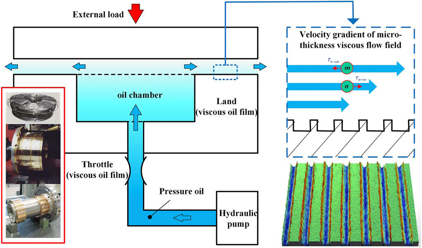
Since the carrying capacity of hydrostatic bearings is achieved based on the formation of a high-stiffness viscous oil film with a 20-micron thickness (less than the viscous bottom layer thickness of pressure oil) (Liu et al., 2017), although hydrostatic bearings have a high operation accuracy and bearing capacity (Kim et al., 2015), the heat generation problem of the viscous oil film is also serious (Liu et al., 2018). Generally, an oil film temperature rise (Liu et al., 2016) can cause its viscosity decrease and lead to an increase in the contact probability between bearing working surfaces and the occurrence of “shaft scraping” and other malignant accidents. Moreover, part of the oil film heat generation can also be transmitted to the bearing structure and cause its thermal deformation, thus disturbing the bearing accuracy stability (Liu et al., 2016). As shown in Figure 1, a microgroove working surface can potentially inhibit heat generation of the viscous oil film and effectively avoid bearing failure caused by the heat effect of the hydrostatic oil film by improving its mechanical properties such as lubrication and adhesion of the working surface of the hydrostatic bearing (Tang et al., 2010).
For the oil film heat generation investigations of hydrostatic bearings under the influence of the microgroove working surface, many scholars have carried out the following relevant research studies by the analytical method and numerical simulation method.
Some scholars have studied the thermal effect mechanism modeling of hydrostatic bearings. Liu et al. (2015) constructed an analytical model of viscous oil film heat generation on a smooth working surface and applied the calculation results as the thermal load of the oil film into the thermo-fluid-solid coupling numerical simulation model of the hydrostatic bearing. Thus, its working conditions–thermal characteristics prediction model was constructed, and the influence mechanism of temperature rise on the viscosity and stiffness of the hydrostatic oil film was revealed. Yu et al. (2018), Yu et al. (2019) studied the thermal deformation characteristics of friction pairs of hydrostatic bearings by using the thermal-fluid-solid coupling numerical simulation method in order to solve the problems of uneven deformation and bearing capacity reduction caused by oil film temperature rise. The mechanism of friction damage of the hydrostatic bearing is revealed, which provides a theoretical basis for performance optimization of the hydrostatic thrust bearing. Tang et al. (2016) studied the influence of the thermal effect on the hydrostatic slipper bearing capacity of the axial piston pump, and the results showed that the slipper bearing capacity increases dramatically with decreasing thermal equilibrium clearance. Zhang et al. (2019), based on the finite volume method, studied the temperature rise and viscosity variation of oil films under the high-speed operation of hydrostatic bearings, revealed the thermal rule of hot oil carrying (HOC), and defined the factor of HOC. In order to study the influence of different viscosity characteristics on the thermal characteristics of fan-shaped oil pads, Huang et al. (2019) compared and analyzed the oil chamber pressure and oil film temperature rise under the temperature–viscosity and pressure–viscosity characteristics based on Fluent software, and the results showed that the temperature–viscosity effect had a greater impact on the thermal characteristics of the oil film than the pressure–viscosity effect. Research studies on the thermal effect mechanism modeling of hydrostatic bearings are mostly based on the assumption of a smooth working surface, while the mechanism of flow and viscous heat generation of hydrostatic bearings on a microstructure working surface is not clear at present.
Other scholars have studied the working surface texture and microstructure characteristics of hydrostatic bearings and their influence. Wang et al. (2016) analyzed the influence of roughness, hydrodynamic, and thermodynamic coupling factors on the pressure distribution and bearing capacity of oil pads of circular hydrostatic bearings based on Christensen’s stochastic model of rough surfaces. Kumar and Sharma (2017) studied the combined influence of couple stress lubricants, tilt between bearing pad surfaces, surface roughness, and other factors on hydrostatic bearing performance. Stokes’s microcontinuum theory and numerical simulation method are used to study the influence of bearing clearance and bearing bush surface inclination on the performance of hydrostatic bearings. Liu and Hu (2018) studied the influence mechanism of different oil supply pressures, oil groove depth, and surface roughness on dynamic and static characteristics of hydrostatic bearings of the precision turntable by using the thermal-fluid-solid coupling numerical simulation method. Comparative analysis shows that the proposed model is more accurate than the traditional model. Lin et al. (2018) studied the influence mechanism of bearing surface texture on characteristics of journal displacement and eccentricity of hydrostatic sliding bearings by using the fluid-solid coupling numerical simulation method. The results showed that the circumferential position of surface texture has an obvious influence on bearing capacity. The research on the surface texture and microstructure morphology of hydrostatic bearings focuses on the analysis of the influence on bearing dynamic/static characteristics, bearing capacity, and other aspects, but the influence on the viscous thermal effect of the hydrostatic bearing fluid layer is not clear.
To sum up, most of the research studies on the modeling of the thermal effect mechanism of hydrostatic bearings are based on smooth working surface conditions, and most of the research studies on the microgroove working surface of hydrostatic bearings focus on the influence mechanism and improvement of bearing dynamic/static characteristics and bearing capacity. However, the effect mechanism of the functional surface of the microgroove on oil film heat generation of hydrostatic bearings is not clear.
In this study, an oil film heat generation model of a hydrostatic bearing with a microgroove working surface is established by combining the analytical model of viscous oil film flow and the numerical simulation of the flow field. The purpose is to explore the influence of surface microgroove design scale variation on hydrostatic bearing oil film velocity gradient and heat generation inhibition and to provide theoretical support for the hydrostatic bearing microgroove oil film heat generation inhibition surface design method. As shown in Figure 2, the heat generation analytical model of the oil film of hydrostatic bearings is first derived. Meanwhile, the finite element method is used to simulate the flow field of a two-dimensional (2D) simplified model of the oil film of hydrostatic bearings, and the numerical simulation model is established and its validity is verified by an analytical model. On this basis, the flow field simulation of the oil film of the hydrostatic bearing with the rectangular microgroove working surface is carried out by using the verified effective numerical simulation method. Combined with the heat generation analytical model of the hydrostatic bearing oil film, the heat generation model of the hydrostatic bearing oil film on the rectangular microgroove working surface is established. On this basis, the influence of rectangular microgroove design scales on oil film heat generation is studied.
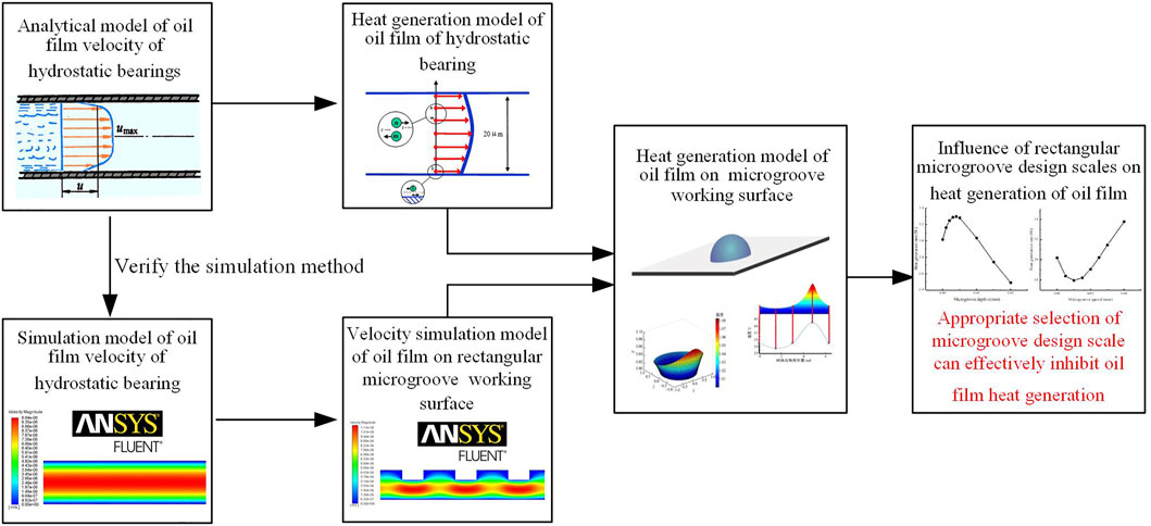
FIGURE 2. Research method of the influence of rectangular microgroove design scale variation on oil film heat generation.
Modeling Method of Oil Film Heat Generation for Hydrostatic Bearings
As shown in Figure 3, there is an annular oil sealing working face on the oil chamber of the hydrostatic bearing, and the oil film flow field on it can be considered as a viscous fluid flowing in the two-plane gap h. Along the oil sealing working face, the oil film’s physical parameters, load conditions, and flow characteristics can be seen as constant values, and the length is short in the X-direction, so the flow field can be considered asinfinitely wide in the Z-direction; then,
Since the thickness of the viscous oil film of the hydrostatic bearing is less than the thickness of the viscous bottom layer of pressure oil, the flow can be considered laminar flow (Ji and Chen, 2012). Liu et al. (2015) established the calculation method of frictional heat generation of viscous fluids in parallel plane clearance:
where
Simulation Modeling Method for the Oil Film Flow Field of the Hydrostatic Bearing With a Smooth Working Surface
Simulation Modeling Method
Based on the main design parameters of the oil film on an oil sealing working face of the hydrostatic bearing, the fluid-structure coupling numerical simulation of the hydrostatic bearing oil film is carried out in ANSY-FLUENT, and the analysis type is set as 2D, as shown in Figure 4. Set the upper and lower sides as walls, and set the left and right sides as inlets and outlets, respectively. The model is meshed and the flow of pressure oil in the gap is simulated in Fluent. Since the thickness of the oil film (2 × 10⁻² mm) is less than the thickness of the viscous bottom layer of hydraulic oil, the flow is laminar flow, so the viscous flow model of pressure oil is set as a laminar flow model. The flow is caused by a pressure difference, so the pressure inlet is set as 1.5 MPa, the pressure outlet is set as 0 MPa, and other boundary conditions remain default. The length of the pressure oil flow direction (X-direction) is 6 mm, and the direction of oil film thickness is the Y-direction. As the temperature rise of the oil film of hydrostatic bearings at a low speed (100 r/min) and a light load (less than 10 t) is no more than 3°C (Zhang et al., 2020), the temperature rise has little influence on the viscosity of pressure oil, so the viscosity of hydraulic oil η can be regarded as a constant value of 1.27 × 10⁻² Pa s, and the pressure oil density ρ is 865 kg/m3.
Grid Independence Verification
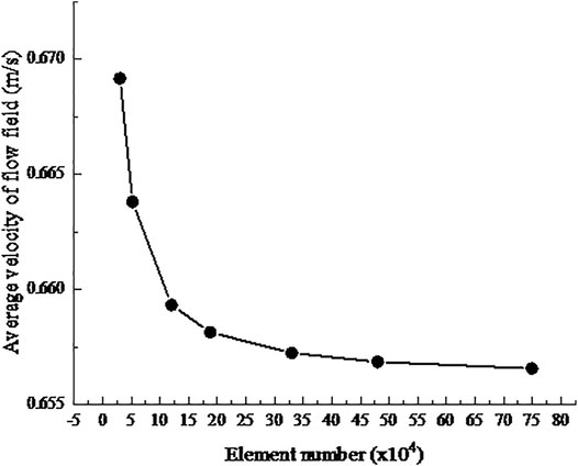
As shown in Figure 5, seven grids with different sizes of 2 × 10⁻³ mm, 1.5 × 10⁻³ mm, 1 × 10⁻³ mm, 8 × 10⁻⁴ mm, 6 × 10⁻⁴ mm, 5 × 10⁻⁴ mm, and 4 × 10⁻⁴ mm are selected for verification for the 2D simplified oil film model. As can be seen from the chart, when the element number reaches 1.2 × 10⁵, the average velocity of the oil film flow field tends to be stable, and the relative error of the calculation results of two adjacent element sizes drops below 0.18%, which can be ignored. With the consideration of the simulation quality and efficiency, the element size is selected as 8 × 10⁻⁴ mm, the element number is 1.875 × 10⁵, and the element quality and aspect ratio of the grid reached 0.995 and 1.0037, respectively. The grid quality meets the requirements.
Reliability Verification of the Simulation Modeling Method
The reliability of the numerical simulation method above can be verified by comparing the simulation results of the oil film flow field with the calculation results of the flow analytical model established by Zhong and Zhang (2007).
Figure 6 shows the simulation results of the oil film velocity field of the hydrostatic bearing with a smooth working surface. The velocity along the flow direction is almost constant. Perpendicular to the flow direction (along the thickness direction), the flow velocity decreases from the middle of the flow field to the wall surface and presents a symmetrical distribution on the middle line of oil film thickness, that is, the flow velocity presents a symmetrical distribution trend of “large in the middle and small on both sides” along the thickness direction. This is consistent with the conic curve distribution corresponding to the flow velocity distribution equation (Zhong and Zhang, 2007), which lays a foundation for verifying the reliability of the simulation method. The average velocity can be obtained by calculating the area-weighted average of the flow field.
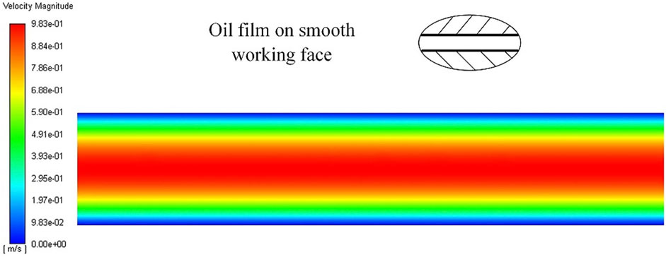
FIGURE 6. Simulation results of the oil film velocity field of the hydrostatic bearing with a smooth working surface.
For the oil film of the hydrostatic bearing with a smooth working surface, it can be considered as a viscous fluid flowing in the double smooth plane gap h, and its flow rate Qsmooth is (Zhong and Zhang, 2007):
Thus, the average flow velocity of the flow field can be calculated:
Table 1 lists the comparison of the average velocity obtained by flow field simulation and analytical calculations under different working conditions for the oil film model of the hydrostatic bearing. The relative errors of both are less than 0.55%, which can be considered basically consistent, proving the reliability of the oil film flow field simulation method of hydrostatic bearings established above.

TABLE 1. Comparison of average velocity obtained by flow field simulation and analytical calculations under different working conditions.
Simulation Modeling Method for the Oil Film Flow Field of the Hydrostatic Bearing With a Smooth Working Surface
Simulation Modeling Method for the Oil Film Flow Field of the Hydrostatic Bearing With a Rectangular Microgroove Working Surface
As shown in Figure 7, based on the simulation method above, the geometric model of the oil film of the hydrostatic bearing with a rectangular microgroove working surface is established. First, the design dimensions of microgrooves are defined: the microgrooves on the working surface of hydrostatic bearings are processed by laser, and their cross-section shape along the Z-direction is rectangular. The side length of the rectangle along the flow direction is defined as microgroove span d, the side length perpendicular to the flow direction is defined as microgroove depth s, and the distance between two adjacent edges with the smallest distance is defined as microgroove spacing j. On this basis, the design dimensions of rectangular microgrooves are empirically determined: depth s = 0.008 mm, span d = 0.03 mm, and groove spacing j = 0.02 mm.

FIGURE 7. Geometric model of the oil film of the hydrostatic bearing with a rectangular microgroove working surface.
Figure 8 shows the simulation results of the oil film velocity field of the hydrostatic bearing with a rectangular microgroove working surface. It can be seen that due to the existence of microgrooves, the velocity distribution of the oil film flow field is different from that of smooth working surface hydrostatic bearings. Along the flow direction, the velocity near the midline of thickness shows a periodic peak value and decreases in all directions with the peak value as the center, forming a periodic “velocity peak” which is located between the two microgrooves. Along the thickness direction, the velocity distribution is no longer symmetric about the thickness midline.
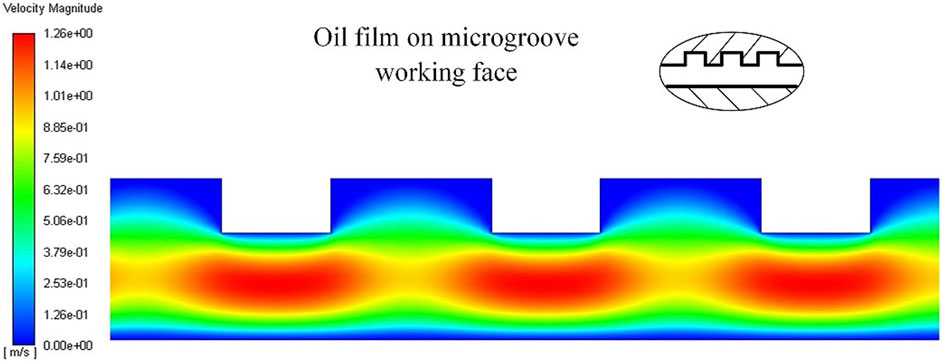
FIGURE 8. Simulation results of the oil film velocity field of the hydrostatic bearing with a rectangular microgroove working surface.
Modeling Method for Oil Film Heat Generation of Hydrostatic Bearings With a Rectangular Microgroove Working Surface
For the oil film of the hydrostatic bearing with a smooth working surface, the heat generation model can be established by substituting Eq. 3 into Eq. 2:
Similarly, the flow field simulation modeling method above is applied to the oil film of the hydrostatic bearing with a rectangular microgroove working surface. The area-weighted average of the flow field can be calculated to obtain the average flow rate, and then the flow rate Qmicro of the flow field can be calculated:
Since the flow is equal everywhere in the flow field, h is taken as the oil film thickness at the position without a microgroove for easy calculations.
By substituting Eq. 6 into Eq. 2, the heat generation rate of the oil film can be calculated as
Here, the numerical simulation method and analytical modeling method are combined to establish the oil film heat generation model of the hydrostatic bearing with a rectangular microgroove working surface.
Effect of Rectangular Microgroove Design Scales on Heat Generation of the Oil Film
On the basis of the numerical simulation method above and the heat generation modeling method, the control variable method is adopted to simulate the effect of design scale variation on oil film heat generation by constantly changing the design scales of microgrooves. In addition, the heat generation rate of the oil film of the hydrostatic bearing with the rectangular microgroove working surface is compared with that of the hydrostatic bearing with a smooth working surface to determine the design scales of the microgroove with heat generation inhibition functions.
Influence of Microgroove Depth Variation on Heat Generation of the Oil Film
Table 2 lists design dimensions of rectangular microgrooves of several groups. The microgroove span and spacing remain constant, and the depth increases by 0.001 mm from 0 and 0.005 mm from 0.005 mm. With the consideration of the actual processing difficulty and the relationship between microgroove depth and oil film thickness, the maximum microgroove depth is restricted to 0.02 mm because the oil film thickness is 0.02 mm. The corresponding heat generation rates are calculated and recorded in the table.
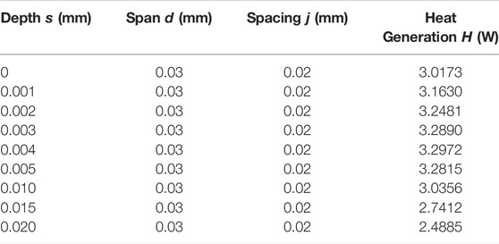
TABLE 2. Design scales of the rectangular microgroove (depth variation) and heat generation rate of the corresponding oil film.
Figure 9 reveals the influence rule of depth variation of rectangular microgrooves on the heat generation rate of the oil film. The abscissa of the curve shows that in the design scales of the microgroove, depth s is a variable, and the other two quantities remain constant. The ordinate of the graph represents the heat generation rate of the oil film at this design scale. The simulation results corresponding to each data point are leaded by dotted lines and displayed intuitively on both sides of the curve. As the depth of the microgroove increases from 0, the heat generation rate of the oil film increases first and then decreases. When the depth increases to 0.01 mm, the heat generation rate approaches the value of the oil film on the smooth working surface and continues to decrease with the depth increase. When the depth is less than 0.004 mm, the shallow microgroove does not hinder the flow but affects the flow velocity gradient and increases the heat generation rate. On the contrary, when the depth is greater than 0.004 mm, the microgroove produces local liquid resistance, the flow velocity decreases, and the heat generation rate decreases. However, as the depth increases to 0.010 mm or more, part of the viscous fluid remains in the microgroove, which slows down the flow rate and decreases the heat generation rate significantly. In this case, the microgroove working surface has a thermal inhibition effect compared to the oil film on the smooth working surface.
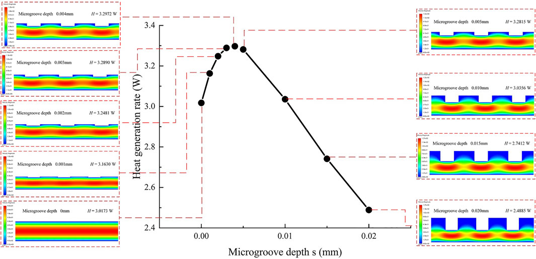
FIGURE 9. Effect of depth variation of the rectangular microgroove on heat generation rate of the oil film.
Influence of Microgroove Span Variation on Heat Generation of the Oil Film
In Table 3, the microgroove depth and spacing remain constant, and the span increases gradually by an increment of 0.005 mm. In order to study the influence of microgroove span in a larger range, the span increases gradually by 0.01 mm after increasing to 0.03 mm.
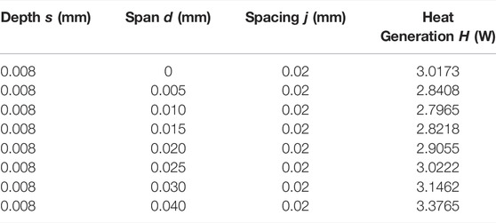
TABLE 3. Design scales of the rectangular microgroove (span variation) and heat generation rate of the corresponding oil film.
The influence of span variation of the rectangular microgroove onto the heat generation rate is shown in Figure 10. The abscissa of the graph indicates that span d is a variable, and the remaining two quantities in the design scale remain constant. The ordinate of the graph represents the heat generation rate of the oil film at this design scale. As the microgroove span increases from 0, the heat generation rate of the oil film decreases first and then increases, and the turning point is 0.01 mm. After the span increases to 0.025 mm, the heat generation rate of the oil film approaches the value of the oil film on the smooth working surface and continues to increase. When the span is less than 0.01 mm, compared with the oil film on a smooth working surface, the microgroove produces local liquid resistance, which reduces the flow rate and heat generation rate. At this time, the microgroove working surface has the effect of heat generation inhibition. As the span of the microgroove gradually increases, the viscous fluid gradually flows fully in the groove, local liquid resistance decreases, the flow rate increases, and the heat generation rate begins to rise. When the span is larger than 0.025 mm, the microgroove begins to promote the flow and the heat generation rate continues to increase. At this time, the working surface of the microgroove no longer inhibits the heat generation.
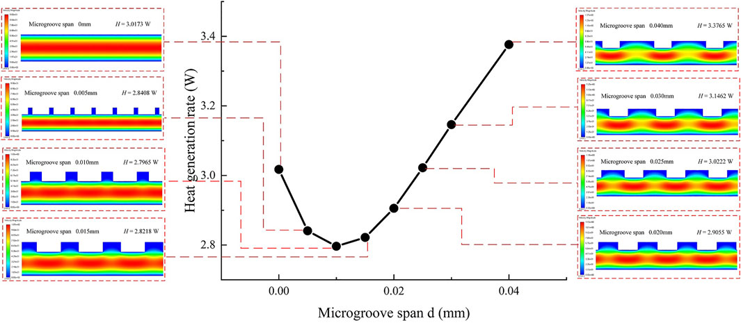
FIGURE 10. Effect of span variation of the rectangular microgroove on heat generation rate of the oil film.
Influence of Microgroove Spacing Variation on Heat Generation of the Oil Film
In Table 4, the depth and span of microgrooves remain unchanged, and the spacing increases gradually with an increment of 0.005 mm and presents a multiple growth after increasing to 0.02 mm so as to study the influence of spacing changes in a wider range on oil film heat generation.
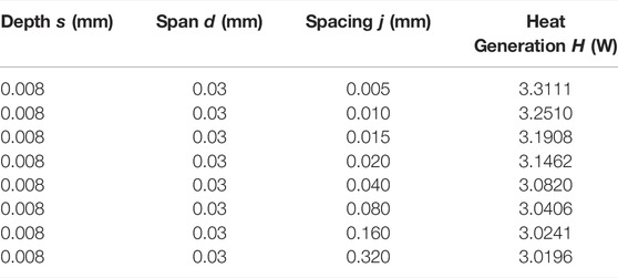
TABLE 4. Design scales of the rectangular microgroove (spacing variation) and heat generation rate of the corresponding oil film.
Figure 11 shows the influence of spacing variation of rectangular microgrooves on the heat generation rate. The abscissa of the graph indicates that spacing j is a variable, and the remaining two quantities in the design scale remain constant. The ordinate of the graph represents the heat generation rate of the oil film at this design scale. As the distance between rectangular microgrooves increases from 0.005 mm, the heat generation rate continues to decrease and is always greater than the value of the oil film on the smooth working surface. It can be seen that compared with the oil film on the smooth working surface, the microgroove working surface of these design scales not only does not produce a heat generation inhibition effect but also promotes the flow and heat generation of the viscous fluid. However, with the increase of spacing, the number of grooves in the same process decreases, the decreasing rate of heat generation slows down, and the influence of microgrooves weakens. When the spacing increases to 0.32 mm, the heat generation rate of the oil film is close to the value of the oil film on the smooth working surface because the distribution of microgrooves is sparse enough to approximate the situation of the smooth working surface.
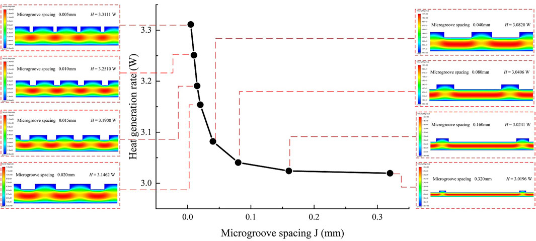
FIGURE 11. Effect of spacing variation of the rectangular microgroove on heat generation rate of the oil film.
According to the above study, as the design scale of the microgroove changes, the working surface will affect the flow velocity gradient of the oil film flow field, making its heat generation rate greater or less than the value of the oil film on the smooth working surface, that is, to promote or inhibit the heat generation of the oil film. Therefore, with the appropriate scales of rectangular microgrooves, the working surface with microgrooves can reduce the average velocity of the viscous flow field of the hydrostatic bearing oil film and restrain its energy loss and heat generation.
Conclusion
In this study, the flow field simulation modeling method of the oil film of the hydrostatic bearing is established and verified by the analytical model. The method is applied to the oil film model of the hydrostatic bearing with a rectangular microgroove working surface, and the flow characteristics and velocity distribution of the oil film flow field are analyzed. Combined with the heat generation modeling method of the hydrostatic bearing oil film on the smooth working surface, the heat generation model of the hydrostatic bearing oil film on the rectangular microgroove working surface is established. On this basis, the influence of three design dimensions, namely, the depth, span, and spacing of rectangular microgrooves, on the heat generation of the oil film of hydrostatic bearings with a rectangular microgroove working surface is analyzed, and the conclusions are as follows:
1) The oil film simulation modeling method of hydrostatic bearings proposed in this study is verified and reliable. It can accurately calculate the average velocity of the oil film flow field, and the heat generation model established on this basis is reliable.
2) Compared with the oil film on the smooth working surface of the hydrostatic bearing, the working surface with appropriate rectangular microgroove design scales can reduce the average velocity of the oil film flow field and inhibit the energy loss and heat generation effect of the oil film.
3) Based on the method in this study, the design scale of microgrooves with heat generation inhibition effects can be obtained from the research results. Design scale range with heat generation inhibition effect: depth 0.010–0.020 mm and span 0–0.025 mm. With the increase of microgroove spacing, the heat generation rate decreases continuously and the working surface has no heat generation inhibition effect. The research results have a guiding significance for the design of microgroove working surfaces of the hydrostatic bearings with heat generation inhibition functions.
Research Prospect
The study of the oil film heat generation mechanism of hydrostatic bearings with a microgroove working surface can provide theoretical support for the design of microgroove working surfaces with heat generation inhibition functions. This research can be widely applied to the improvement of the key performance of high-end precision machinery, which is of great significance to the development of high-end manufacturing, national defense technology, aerospace, and other strategic fields, and has a broad application prospect.
Data Availability Statement
The raw data supporting the conclusion of this article will be made available by the authors, without undue reservation.
Author Contributions
TL and RD provide research ideas and guidance for CL and HQ. CL and HQ carried out all the calculation work and wrote the original manuscript. FC and ZZ are responsible for the revision of the paper. JZ and ZS designed the logical structure of the whole manuscript.
Funding
This study was supported by the National Natural Science Foundation of China (No. 52005152), the Natural Science Foundation of Hebei, China (No. E2021202117), the National Natural Science Foundation of China (No. 52105477), and the National Natural Science Foundation of China (No. 51875166).
Conflict of Interest
The authors declare that the research was conducted in the absence of any commercial or financial relationships that could be construed as a potential conflict of interest.
Publisher’s Note
All claims expressed in this article are solely those of the authors and do not necessarily represent those of their affiliated organizations or those of the publisher, the editors, and the reviewers. Any product that may be evaluated in this article or claim that may be made by its manufacturer is not guaranteed or endorsed by the publisher.
References
Huang, Z., Chen, L., Jia, Z. J., and Wang, L. P. (2019). Study on Thermal Characteristics of CNC Hydrostatic Turntable Oil-Film Considering Viscosity Effects. J. Univ. Electro. Sci. Tech. 48, 627–632. doi:10.3969/j.issn.1001-0548.2019.04.022
Ji, B., and Chen, J. (2012). ANSYS ICEM CFD Mesh Division Technology Examples. Beijing: China Water Resources and Hydropower Press, 78–82.
Kim, B.-S., Bae, G.-T., Kim, G.-N., Moon, H.-M., Noh, J.-P., and Huh, S.-C. (2015). A Study on the thermal Characteristics of the Grinding Machine Applied Hydrostatic Bearing. Trans. Can. Soc. Mech. Eng. 39, 717–728. doi:10.1139/tcsme-2015-0057
Kumar, V., and Sharma, S. C. (2017). Study of Annular Recess Hydrostatic Tilted Thrust Pad Bearing under the Influence of Couple Stress Lubricant Behaviour. Int. J. Surf. Sci. Eng. 11, 344–369. doi:10.1504/IJSURFSE.2017.10008356
Lin, Q., Bao, Q., Li, K., Khonsari, M. M., and Zhao, H. (2018). An Investigation into the Transient Behavior of Journal Bearing with Surface Texture Based on Fluid-Structure Interaction Approach. Tribol. Int. 118, 246–255. doi:10.1016/j.triboint.2017.09.026
Liu, C., and Hu, J. (2018). A FSI-thermal Model to Analyze Performance Characteristics of Hydrostatic Turntable. Indu. Lubr. Tribol. 70, 1692–1698. doi:10.1108/ILT-09-2017-0250
Liu, T., Gao, W., Tian, Y., Mao, K., Pan, G., and Zhang, D. (2015). Thermal Simulation Modeling of a Hydrostatic Machine Feed Platform. Int. J. Adv. Manuf. Technol. 79, 1581–1595. doi:10.1007/s00170-015-6881-0
Liu, Z. F., Zhan, C. P., Cheng, Q., Zhao, Y. S., Li, X. Y., and Wang, Y. D. (2016). Thermal and Tilt Effects on Bearing Characteristics of Hydrostatic Oil Pad in Rotary Table. J. Hydrodyn. 28, 11. doi:10.1016/S1001-6058(16)60662-5
Liu, Z., Wang, Y., Cai, L., Zhao, Y., Cheng, Q., and Dong, X. (2017). A Review of Hydrostatic Bearing System: Researches and Applications. Adv. Mech. Eng. 9, 168781401773053. doi:10.1177/1687814017730536
Liu, P., Chen, W., Su, H., and Chen, G. (2018). Dynamic Design and thermal Analysis of an Ultra-precision Flycutting Machine Tool. Proc. Inst. Mech. Eng. B: J. Eng. Manuf. 232, 404–411. doi:10.1177/0954405416645257
Tang, Y., Zhou, M., Han, Z. W., and Wan, Z. P. (2010). Recent Research on Manufacturing Technologies of Functional Surface Structure. JME 46, 93–105. doi:10.3901/jme.2010.23.093
Tang, H.-s., Yin, Y.-b., Zhang, Y., and Li, J. (2016). Parametric Analysis of thermal Effect on Hydrostatic Slipper Bearing Capacity of Axial Piston Pump. J. Cent. South. Univ. 23, 333–343. doi:10.1007/s11771-016-3078-0
Wang, Y., Zhao, Y., Cai, L., Liu, Z., and Cheng, Q. (2016). Effects of thermal and Hydrodynamic Characteristics of Heavy-Duty Rotary Table on the Hydrostatic Circular Pads. J. Vibroeng. 18, 4193–4206. doi:10.21595/jve.2016.17079
Yu, X., Zuo, X., Liu, C., Zheng, X., Qu, H., and Yuan, T. (2018). Oil Film Shape Prediction of Hydrostatic Thrust Bearing under the Condition of High Speed and Heavy Load. Ind. Lubr. Tribol. 70, 1243–1250. doi:10.1108/ILT-07-2017-0220
Yu, M., Yu, X., Zheng, X., and Jiang, H. (2019). Thermal-fluid-solid Coupling Deformation of Hydrostatic Thrust Bearing Friction Pairs. Ind. Lubr. Tribol. 71, 467–473. doi:10.1108/ILT-07-2018-0262
Zhang, Y., Kong, P., Feng, Y., and Guo, L. (2019). Hot Oil Carrying Characteristic about Hydrostatic Bearing Oil Film of Heavy Vertical Lathe in High Speed. Indu. Lubr. Tribol. 71, 126–132. doi:10.1108/ILT-03-2018-0091
Zhang, Y. Q., Feng, Y. N., Ni, S. Q., and Luo, Y. (2020). Temperature Rise Characteristics of Beveled Oil Pad Hydrostatic Bearing under the Influence of Hot Oil Carrying. J. Huazhong Univ. Sci. Tech. Nat. Sci. 48, 122–127. doi:10.13245/j.hust.200721
Keywords: hydrostatic bearing, oil film, viscous heat generation, microgroove structure surface, numerical simulation
Citation: Liu T, Li C, Duan R, Qu H, Chen F, Zhou Z, Zhang J and Shi Z (2022) Viscous Oil Film Thermal Modeling of Hydrostatic Bearings With a Rectangular Microgroove Surface. Front. Energy Res. 10:891380. doi: 10.3389/fenrg.2022.891380
Received: 07 March 2022; Accepted: 28 March 2022;
Published: 27 April 2022.
Edited by:
Xiao Liu, Harbin Engineering University, ChinaCopyright © 2022 Liu, Li, Duan, Qu, Chen, Zhou, Zhang and Shi. This is an open-access article distributed under the terms of the Creative Commons Attribution License (CC BY). The use, distribution or reproduction in other forums is permitted, provided the original author(s) and the copyright owner(s) are credited and that the original publication in this journal is cited, in accordance with accepted academic practice. No use, distribution or reproduction is permitted which does not comply with these terms.
*Correspondence: Runze Duan, ZHVhbnJ1bnplQGhlYnV0LmVkdS5jbg==
 Teng Liu1,2
 Runze Duan
 Faze Chen