 Y. Xiao
 T. C. Duan1
 Quan-Yao Ren
94% of researchers rate our articles as excellent or good
Learn more about the work of our research integrity team to safeguard the quality of each article we publish.
Find out more
METHODS article
Front. Energy Res. , 12 May 2022
Sec. Nuclear Energy
Volume 10 - 2022 | https://doi.org/10.3389/fenrg.2022.891074
This article is part of the Research Topic CFD Applications in Nuclear Engineering View all 16 articles
The spacer grid has a significant impact on the thermal-hydraulic characteristics of the rod bundle channel, which directly determines the possibility of a boiling crisis. The multi-phase flow model coupling boiling model is proposed to acquire the secondary flow and void fraction for subcooled flow boiling in the fuel assembly. Compared with the experimental data, the RNG k–ε turbulence model is selected in the current research. In addition, the thermal-hydraulic parameters of subcooled boiling flow in the 5 × 5 rod bundle with a spacer grid are studied focusing on the influence of different arrangements of mixing vanes. It is found that the distribution of the vapor phase is greatly influenced by the intensity and flow direction of secondary flow. In addition, the thermal–hydraulic characteristics in the sub-channels and around the fuel rods are investigated, which demonstrates that uniform crossflow makes vapor harder to accumulate around the fuel rods. Furthermore, the mixing characteristics of different types of spacer grids are also discussed in detail.
• The multiphase flow model coupling boiling model has been applied in the fuel assembly.
• The distribution of secondary flow, secondary flow intensity, axial velocity, and void fraction has been discussed.
• The thermal-hydraulic characteristics of sub-channels and fuel rod surfaces have been analyzed.
• The numerical results of secondary flow intensity are proven to be in good agreement with experimental data.
The main purpose of thermal-hydraulic research in the nuclear reactor is to improve the heat transfer and its uniformity so that to keep more heat away from the fuel rod surface and increase the critical heat flux. As a component existing in the heating section of the fuel rod, the spacer grid directly affects the flow and heat transfer characteristics in the fuel assembly. The swirl flow in a rod bundle with a spacer grid includes natural convection and forced convection. Natural convection occurs in the rod bundle sub-channel, while forced convection is produced due to the strong disturbance of the fluid caused by the leaf springs, dimples, and mixing vanes in the spacer grid. The 17 × 17 rod bundles are used in the nuclear reactor. However, considering the experimental conditions, the number of fuel rods is reduced for research. Among so many studies, the rod bundle size used by the researchers is not consistent, and 5 × 5 rod bundles have been relatively more studied.
For the experimental study of the thermal-hydraulic characteristics in fuel assemblies, there are some differences in the obtained parameters due to different measurement methods. Rehme (1987; 1989) studied the effect of velocity boundary layer reconstruction downstream of the spacer grid on heat transfer and analyzed the fluid pulsation between channels through the measured interleaving coefficient. It is shown that the exchange of heat is mainly caused by the hydrodynamic interaction between channels. Wu and Trupp (1993) measured the axial velocity of the coolant between the rod bundles and the distribution of turbulent kinetic energy by a hotline instrument. The experimental results showed that the axial turbulent kinetic energy of the sub-channels between the rod bundle and the near-wall surface was higher than that of the channels between the rod bundles, and there were differences in the flow patterns as well. McClusky et al. (2002) determined that sub-channel heat transfer is mainly influenced by mixed and interlaced flows. Although the experimental measurements were unsatisfactory due to the shortcomings of the experiment itself, the study still has an important academic value. In the current experimental research, laser Doppler velocimetry (LDV) and particle image velocimetry (PIV) measurements were heavily used because of the high accuracy of measuring the flow field parameters in the fuel assembly. Based on the 4 × 4 rod bundle geometry model with the spacer grid (mixing wing only) in the rectangular frame, Shen et al. (1991) used LDV to measure the crossflow downstream of the spacer grid in the center of the sub-channel and the transverse flow in the gap between fuel rods. This study shows that the turbulence intensity downstream of the spacer grid decays to almost zero at 21Dh, and the greater the angle of the mixing vane, the stronger the crossflow is formed. By using 1-D LDV measurement, Yang and Chung (1996) and Yang and Chung (1998) characterized the variation trend of axial velocity upstream and downstream of fuel assembly with the 5 × 5 rod bundle and the turbulent flow between rod bundles and then explained the turbulent kinetic energy caused by the spacer grid and the physical phenomenon of gradual attenuation of turbulent intensity along the downstream of the spacer grid. The results show that turbulent swirl flow and forced swirl flow occur at 10Dh and 20Dh downstream of the grid, respectively, and the swirl factor reaches the maximum near the spacer grid. Through the flow field downstream of the grid measured by the LDA system, Han et al. (2009) studied the traditional split vane and the new series arranged mixing vane. It shows that the vortex generated by the split mixing vane usually reaches the maximum at 4–5Dh and then decays rapidly, and the strong swirl flow generated by the new mixing vane can last up to 20Dh. The flow field distribution in the rod bundle channel upstream and downstream of the spacer grid was, respectively, measured with PIV by Dominguez-Ontiveros et al. (2009), Dominguez-Ontiveros et al. (2012), Conner et al. (2013), and Dominguez-Ontiveros and Hassan (2014). The research team has carried out a lot of research work on different rod bundle channels with spacer grids in recent years. They used DPIV and MIR methods to capture the distribution of the flow field in the rod bundle. They deeply analyzed the changes of the flow field before and after the spacer grid and also measured the changes of velocity in the 5 × 5 rod bundle channel and the changes of the turbulent flow pattern and mainstream velocity in the 3 × 3 rod bundle channel. The results show that the vortex decreases gradually downstream of the spacer grid due to interaction between the vortex, which can be used for the validation of the computational fluid dynamics (CFD) calculation. In recent years, with the development of experimental technology, many researchers began to pay attention to the two-phase flow characteristics of the coolant in fuel assemblies. Pham et al. (2014; 2015) used a high-speed camera to study the cross-sectional characteristics of the swirl flow in a 3 × 3 rod bundle channel, which revealed the whole change process of the swirl flow. Arai et al. (2012) studied the cavitation behavior and the two-phase flow behavior of the sub-channel in a 10 × 10 rod bundle channel, measured the void fraction and bubble velocity with the advanced cavitation detection system, and established the dynamic behavior of two-phase flow along the flow direction. Cho et al. (2011) studied the change of droplets in the 6 × 6 rod bundle channel when passing through the spacer grid as well as clarified the process of breaking into smaller droplets after droplet entrainment. By observing the characteristics of two-phase flow in a single channel, Liu et al. (2021) studied the effect of the spacer grid on the bubble behavior and the critical heat flux (CHF). Ren et al. (2018a), Ren et al. (2018b), and Ren et al. (2021) carried out the air–water two-phase flow experiment and determined the distribution characteristic of the two phases in the rod bundle channel by using a miniaturized four-sensor conductivity probe (MFSCP).
Since the experimental method has many limitations in the research of the spacer grid, most of the research is still based on numerical methods. Navarro and Santos (2011) studied the hydraulic performance of the 5 × 5 fuel assembly with a split vane spacer grid. The results showed that the numerical results were in good agreement with the experimental values, which confirmed the feasibility of using the numerical method to study the fuel assembly. Cinosi et al. (2014) used STAR-CCM + software to compare the velocity values measured in the experiment with the results calculated by the four turbulence models. It was considered that the standard k–epsilon, k–omega, and Reynolds tress turbulence models could predict the distribution of average velocity, and the difference between the simulation results of the standard k–ε model and the experimental values was the smallest. Also using STAR-CCM + software, Podila and Rao (2016) used the realizable k–ε, k–ω SST, and Reynolds stress models to simulate 5 × 5 rod bundles with a split spacer grid. The results showed that the axial velocities calculated by the three turbulence models were close to the experimental results, but the turbulence intensity obtained by the realizable k–ε model is the closest to the experimental measurement value. Caraghiaur et al. (2009) studied the turbulent flow behavior in the rod bundle with a spacer grid. The result shows that the turbulence intensity downstream of the spacer grid in the sub-channel gradually decreases to less than the one upstream of the grid, then continues to increase until the distance between the two grids is the largest, and then decreases again. However, there is no such sudden increase in the turbulence intensity in the side channel and corner channel, and there is only a little increase when flowing after the mixing vanes. Liu and Ishiwatari (2013) studied the single-phase flow behavior of the sub-channel center under unsteady conditions. The results show that the geometric structure of the sub-channel center, the gap width between fuel rods, and the size of fuel rods have a great influence on the flow. Agbodemegbe et al. (2015; 2016) studied the influence of mixing vanes on crossflow according to the velocity changes of fluid along the deflection direction of vanes as well as in the transverse and axial directions. By comparing with the experimental data, the authors believed that the realizable k–ε model could not accurately predict the velocity fluctuation and established a model to calculate the crossflow resistance coefficient. Liu and Ferng (2010), Chen et al. (2014), and Lin et al. (2014) carried out in-depth research on the thermal-hydraulic characteristics of the spacer grid using the CFD method and studied the single-phase flow and heat transfer of the spacer grid with single-channel and the 5 × 5 rod bundle channel with spacer grid, respectively. The study of heat transfer characteristics in a single channel shows that the grid with mixing vanes has a great influence on flow and heat transfer. The comparison between the calculated Nusselt number and the experimental value shows that the numerical method can be used to study the thermal-hydraulic characteristics in fuel assemblies. At the same time, the study also analyzed the thermal-hydraulic characteristics of the rod bundle channel under the condition of non-uniform heating. The results show that there is no obvious difference between the steady-state calculation and the unsteady-state calculation of the 5 × 5 rod bundle channel, and the SST k–ω turbulence model is suitable for the geometric structure. Based on the comparison results of the Nu number downstream of the grid and in the circumferential direction of the fuel rod, it is found that the flow characteristics are the main factors that determine the law of heat transfer. Bakosi et al. (2013) used large eddy simulation (LES) to study the turbulence and mechanical behavior in a single channel. The study shows that LES is suitable for studying the wear between fuel rods and grids. Anglart and Nylund (1996) and Anglart et al. (1997) studied the axial and transverse void distribution in the sub-channel and predicted the variation trend of vapor and liquid flow fields in two-phase flow. Considering the influence of buoyancy drift in the rod bundle channel, Carlucci et al. (2004) explained the relationship between swirl flow in turbulence under the single-phase and two-phase conditions. Yang et al. (2021) proposed a multiphase flow model based on the Euler equation, studied the axial distribution of thermal-hydraulic parameters of subcooled boiling in the 3 × 3 rod bundle channel, and obtained the conclusion that the heat transfer characteristics of the coolant will be significantly reduced when the deflection angle of mixing vanes is greater than 30°. Wang et al. (2020), Khan et al. (2020), and Zhang et al. (2022) have also developed and applied the high fidelity thermal-hydraulic models using the CFD method to analyze flow and heat transfer characteristics of the rod bundles.
Currently, most of the CFD research work is based on the single-phase condition for the thermal-hydraulic characteristics of the rod bundle with the spacer grid. Considering the two-phase flow, especially the two-phase flow under boiling conditions, the two-phase calculation model and the boiling phase transition model needs to be further improved. The CFD calculation results of the single-phase flow in the complex fuel assembly with the grid have limited guidance for the design of the fuel assembly. In addition, the calculation results of single-phase flow cannot reflect the real two-phase flow, especially the distribution characteristics of the void fraction in the fuel assembly and the influence of void fraction distribution characteristics on the critical heat flux. Therefore, it is of great significance to study the two-phase flow in the fuel assembly based on the CFD method (Wang et al., 2021).
In this article, the two-phase flow model and the boiling phase transition model for the complex fuel assembly are first established. Second, based on the CFD method to calculate the two-phase flow in the fuel assembly, the two-phase flow behavior characteristics, including the mixing characteristic of the spacer grid, the secondary flow evolution, the sub-channel characteristics as well as the void fraction distribution characteristics, and their influence on the CHF are studied. The quantitative analysis of the flow parameters will provide theoretical support for the thermal design of the fuel assembly.
The geometric configuration used in this article is a 5 × 5 rod bundle channel with a spacer grid as shown in Figure 1, and the fuel assembly is placed in a 65 mm × 65 mm rectangular frame. The total length of the fuel assembly is 283.8 mm, including the length of the spacer grid downstream and upstream as 228 and 22.8 mm, respectively, and the spacer grid of height 33 mm. A total of 25 fuel rods were used in the fuel assembly with an outer diameter of 9.5 mm, and the rod bundle hydraulic diameter (Dh) is 11.4 mm. The rod bundle with spacer grid is divided into different sections along the flow direction, for which the distance is shown in Table 1. The geometry structure of the spacer grid is very complex, which consisted of dimples, springs, and mixing vanes. On the one hand, the springs and dimples can clamp fuel rods to prevent sloshing. On the other hand, these structural components will produce a very strong secondary flow. Furthermore, the mixing vanes can induce secondary flow intensity, which affects the phase distribution characteristics of the two-phase flow downstream of the spacer grid in the fuel assembly.
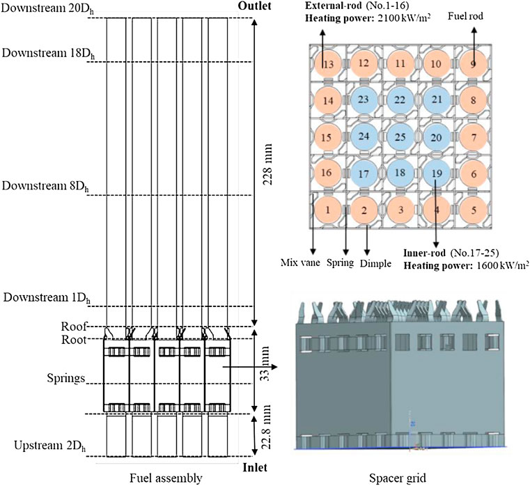
FIGURE 1. Structure of the rod bundle with spacer grid and arrangement of the rods.
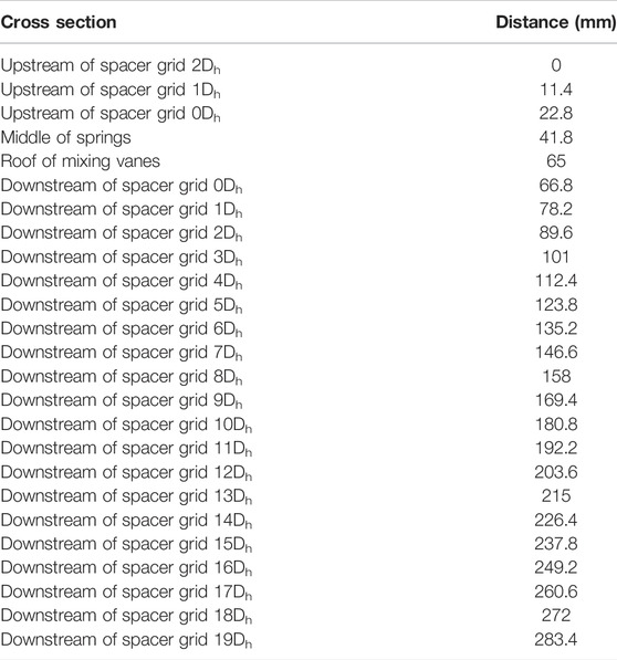
TABLE 1. Distance of different cross sections.
The iterative method of pressure coupling velocity field is performed in this study. The boundary conditions involved are shown in Table 2. A uniform velocity inlet with a mass flow rate of 1990 kg/m2 s is considered, a pressure (12.5 MPa) outlet boundary condition is used for the outlet, the inlet temperature and inlet average void fraction are set to 601 K and 0.39, respectively, and the wall boundary is a no-slip boundary condition. Due to the power distribution of the fuel rods in a nuclear reactor are not uniform, the different heating power of fuel rods is imposed as shown in Figure 1, in which the heating power is 2,100 kW/m2 for the 16 fuel rods (No. 1–16) outside the fuel assembly and 1,600 kW/m2 for the 9 fuel rods (No. 17–25) inside.
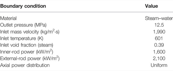
TABLE 2. Operating conditions in two-phase flow.
For most research on flow and heat transfer characteristics in fuel assemblies, the turbulence model generally uses the Reynolds-averaged Navier–Stokes equations due to the complexity of the geometric model. By comparing the experimental measurements with the numerical results, the standard k–ε model can predict the mean velocity better (Cinosi et al., 2014), while the realizable k–ε model calculates the turbulence intensity closer to the experimental measurements (Podila and Rao, 2016). The author of this article concluded that the RNG k–ε model is more suitable for the current calculation conditions through a comparative analysis between the sub-channel temperature obtained by experimental measurements and the results calculated by different turbulence models in previous studies (Chen et al., 2016). In addition, the flow and heat transfer characteristics downstream of the spacer grid under single-phase conditions have been investigated. This article is a further discussion of the thermal-hydraulic characteristic of the downstream of spacer grid under two-phase conditions based on the previous study; therefore, the turbulence model, mesh analysis, near-wall treatment, and numerical solution involved in this study are the same as in the article (Chen et al., 2016) and no longer described in this article. Thus, the RNG k–ε model is used for the flow field and temperature distribution inside the rod bundle. In the present study, Fluent software is adopted to solve nonlinear equations.
Considering that the void fraction in fuel assembly exceeds 10% and the vapor–liquid interface is not required to be tracked, the mixture model is selected to solve the mass, momentum, and energy conservation equations of vapor–liquid two-phase flow in rod bundles. Although the Eulerian model considers the flow of the vapor phase and the liquid phase, it requires huge computational resources and is more difficult to converge. Therefore, the mixture model is applied to calculate the two-phase flow of fuel assemblies with a spacer grid in this article.
Mixture model continuity equation:
where
Mixture model momentum equation:
where
Mixture model energy equation:
where
Volume fraction equation for the secondary phases:
As the heating power increases, fine vapor bubbles start to form on the fuel rod surface and gradually grow into big bubbles on the rod bundle surface. The continuous big bubble separates the heated wall surface from the liquid phase, making a liquid film appear between the big bubble and the heated wall surface. The heated wall delivers energy to the bubble by heat transfer through the micro-layer liquid film, while the vapor–liquid interface transfers energy through convective heat transfer. For the mass transfer process, the vapor generation rate due to the phase change will be calculated based on the energy balance. Therefore, in this article, the process of mass and energy transfer of the phase transition is implanted into the CFD codes through user-defined function (UDF) by considering the heat and mass transfer at the bubble contact area and the phase interface to realize the numerical analysis of the two-phase flow and obtain the phase distribution characteristics in the fuel assembly. The mathematical equations for the mass and energy transfer between phase interfaces during the phase transition are described as follows:
The mass source by phase transition
where the vapor generation rate on the heated wall
where
When the coolant flows through the fuel assembly with the spacer grid, it is affected by the spacer grid belts, springs, dimples, and mixing vanes, which will result in a very strong swirl flow in the lateral direction. Due to the guidance of the design, the mixing of the coolant by the mixing vanes will lead to regular secondary flow
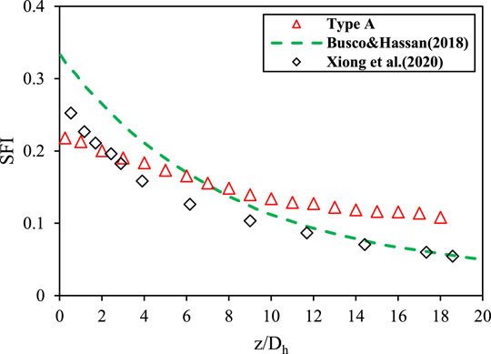
FIGURE 2. Comparison of simulated and experimental secondary flow intensity.
In this article, the effect of spacer grids on the mixing characteristics of two-phase flows in fuel assemblies, especially the evolution of secondary flow between channels after passing through the spacer grid is investigated. Then, the trends of secondary flow and void fraction in different sub-channels under boiling conditions as well as at the downstream of two different spacer grids are compared. Consequently, the swirl capacity of the mixing vane is quantitatively evaluated.
Based on the secondary flow distribution under boiling conditions shown in Figure 3, it can be found that a strong secondary flow begins to appear at the root of the mixing vane and is located in the inclined direction of the mixing vanes. On the contrary, there is no strong secondary flow in the opposite direction. The phenomenon shows that the secondary flow is mainly caused by the mixing vanes, and the direction of the mixing vanes will directly determine the location of the strong vortex. Comparing the secondary flow on the cross sections at 1Dh, 8Dh, and 18Dh, once the coolant flows through the grid region, the fluid mixing and pulsation between different sub-channels makes a non-uniform distribution of the secondary flow intensity downstream of the spacer grid as shown in Figure 4, and different sub-channels will be affected by the energy and mass exchange as well as the wall effects. Because the wall effects of the side sub-channel and corner sub-channel are more obvious than those of the middle sub-channel, the secondary flow of the side sub-channel and middle sub-channel will be smaller. In addition, because of the flow resistance of fuel rods and no further excitation of mixing vanes, the secondary flow continues to weaken at the downstream of the whole spacer grid. As shown in Figure 3, the maximum secondary flows of 1Dh and 18Dh downstream of the grid are 1.7 m/s and 1.1 m/s, respectively. According to the aforementioned analysis, the lateral flow of the flow field downstream of the grid is mainly caused by the mixing vanes, while the structure and arrangement of the mixing vanes have a significant influence on the distribution and intensity of the secondary flow downstream of the grid. However, the influence disappears in a certain distance, and the secondary flow distribution downstream of the grid presents an asymmetric morphology.
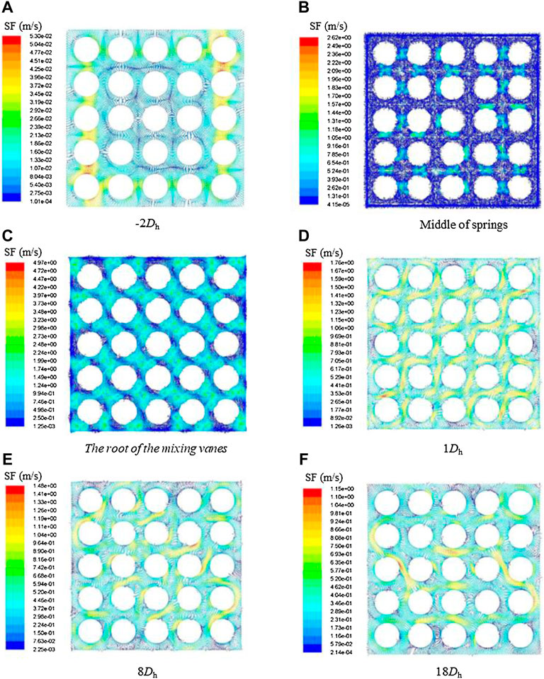
FIGURE 3. Cross-sectional profile of secondary flow along axial direction.
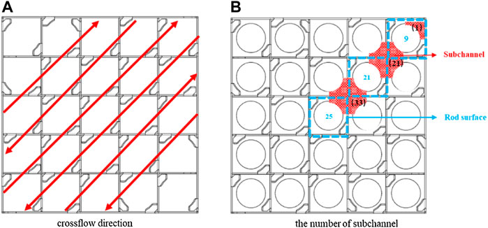
FIGURE 4. Flow direction diagram of secondary flow and sub-channel number.
In the analysis of the thermal-hydraulic characteristics in the rod bundle channel, the flow field on the cross section along the flow direction cannot fully express the local characteristics, but the changing trend of the flow pattern in the sub-channel can truly reflect the heat transfer characteristics of the internal flow. Meanwhile, the flow field on the surface of the fuel rod is also selected to study its importance on the critical heat flux. In this article, the average secondary flow evolution in adjacent sub-channels and on the fuel rod surfaces is analyzed, and the selected sub-channels and fuel rods are shown in Figure 4. Since the sub-channel data cannot be extracted by the original calculation software, they are obtained by UDF.
According to the arrangement of mixing vanes of the current spacer grid, three sub-channels, including two middle sub-channels (21 and 33) and one corner sub-channel (1), and the surfaces of three corresponding fuel rods (9, 21, and 25) are selected as the research objects. The secondary flow curves along the axial direction in the three sub-channels and on fuel rod surfaces are shown in Figure 5. As one can see, the secondary flow along the axial direction shows a similar trend for both the sub-channel and the fuel rod surface roughly. The largest secondary flow all appears at the top of the mixing vanes and then gradually attenuates along the downstream of the grid, while the secondary flow at the root of the mixing wing is about 1 m/s, which indicates that the springs and dimples in the spacer grid will also cause the transverse mixing of the coolant. For different sub-channels, the secondary flow of the corner channel is only caused by a single vane and limited by the casing tube, while in the middle channels it is affected by a pair of mixing vanes. The secondary flow in the corner channel at the upstream and downstream of the spacer grid is smaller than that in the other two middle channels. The secondary flow in the corner channel does not decay and fluctuates after 6Dh. This phenomenon mainly lies in the fact that the corner channel is influenced by the wall channel downstream of the grid. For the middle channel, sub-channel 33 is more obviously affected by the transverse pulsation of the surrounding sub-channel flow field than sub-channel 21, so the secondary flow of the former is a little larger than that of the latter before 12Dh. Since the arrangement of the mixing vanes around fuel rod 9 is different from that of fuel rod 21 and fuel rod 25, the secondary flow velocity at the upstream and downstream of the mixing vanes on the surface of fuel rod 9 is greater than that of the other two, and its attenuation rate is also greater. The data analysis shows that the secondary flow in the fuel assembly is mainly caused by the mixing vanes in the spacer grid and attenuates gradually after passing through the grid, but there are differences in the changing trend between different sub-channels.
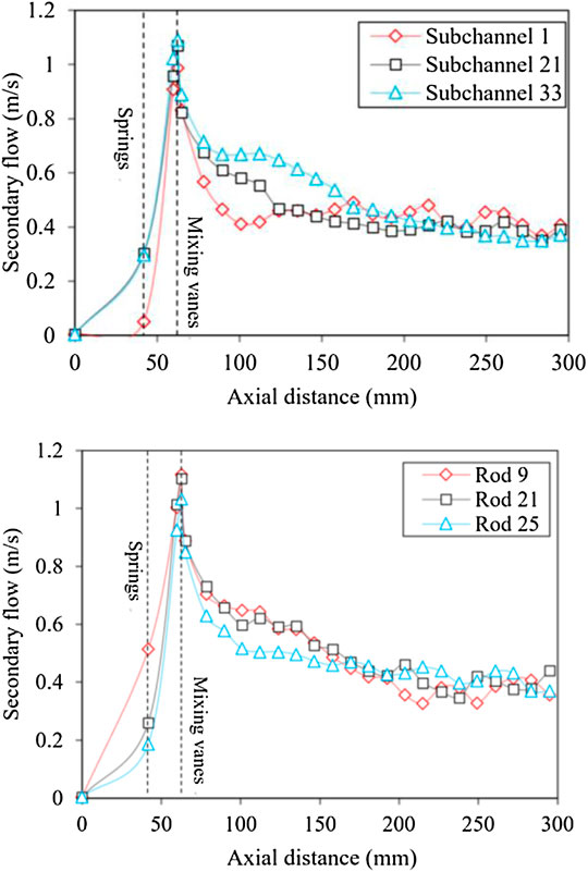
FIGURE 5. Distribution of secondary flow along axial direction in the sub-channel and around the fuel rod.
The boiling crisis is usually under a low void fraction in a pressurized water reactor. In this case, the accumulation of the vapor phase on the surface of the fuel rod and the formation of a vapor film are the key influencing factors for DNB. The phase distribution characteristics of boiling two-phase flow are revealed at the downstream of spacer grid with mixing vanes, and the accumulation degree of vapor on the surface of different fuel rods after passing through the spacer grid is quantitatively studied. Figure 6 shows the vapor phase distribution clouds at the root of the mixing vane, 1Dh, 8Dh, and 18Dh. The vortex at the root of the mixing vane makes the vapor phase involved in the vortex center, resulting in more obvious vapor accumulation around the mixing vanes. With the increase of vortex intensity and bubble growth along the axial direction, more vapor phase is brought into the vortex center along the flow direction, making the vapor phase gather in the center of the sub-channel. However, after 1Dh downstream of the grid, the decrement of vortex intensity and the development of secondary flow lead to non-uniform distribution of vapor phase distribution. Taking fuel rod 14 as an example, the local extreme value of the void fraction on the fuel rod surface is continuously changed along the axial direction due to the influence of secondary flow, and the changing direction of the void fraction is the same as that of secondary flow. Combined with the secondary flow distribution diagram shown in Figure 4, it can be seen that the more uniform distribution of secondary flow around the fuel rod corresponds to a more uniform distribution of the vapor phase because the uniform transverse flow field around the fuel rod will not make the vapor phase stay in this region. As shown in Figure 7, the variation trend of the void fraction increases gradually along the axial flow direction. However, since the secondary flow in the corner channel is larger than that in the middle channel after 12Dh, its void fraction becomes smaller. At the downstream of the spacer grid with mixing vanes, a part of the vapor phase is taken away from the center of the sub-channel and the rest accumulates on the surface of the fuel rod, when it is mixed by the transverse flow. As the transverse mixing capacity decreases gradually along the flow direction, the vapor phase accumulation phenomenon is more obvious in the area far from the downstream of the grid.
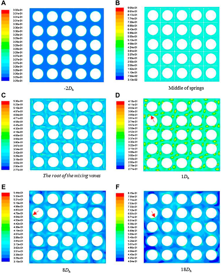
FIGURE 6. Variations of vapor-phase distribution along axial direction.
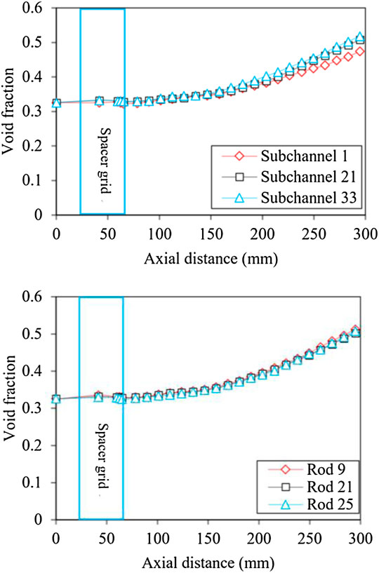
FIGURE 7. Average void fraction along axial direction in the sub-channel and around the fuel rod.
The geometric structure of the spacer grid, especially the arrangement and guidance of its mixing vanes, has a very important influence on the mixing characteristics of the spacer grid. To fully verify the mixing characteristics caused by the spacer grid, it is necessary to analyze the influence of the mixing vane arrangement of the spacer grid on the secondary flow and phase distribution. In this article, two different types of spacer grids are taken as the research objects, and their structures are shown in Figure 8. The type-A grid and the type-B grid have different arrangements of mixing vanes around external fuel rods.
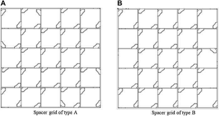
FIGURE 8. Structure of the spacer grids (A) and (B).
From the curves of secondary flow and axial velocities for the cross section along the axial direction in Figure 9, one can see that they increase and then decrease along the flow direction, the maximum value of secondary flow appears at the top of the mixing vanes, and the maximum value of axial velocities appears at the bottom of the spring. The difference in axial velocity between the two types of grids is greater than that in secondary flow. Due to the differences in the arrangement and guidance of the mixing vanes in the two spacer grids, a stronger disturbance occurs in the type-B grid. The larger secondary flow after the grid strengthens the interaction between the lateral flow fields, resulting in a greater decay rate of the mixing flow caused by the mixing vanes of the type-B grid than that of the type-A grid, especially the secondary flow is smaller than that of the type-A after 12Dh downstream of the grid. Because of different mixing capacities and different secondary flows, the axial velocity of the type-B grid is smaller than that of the type-A grid while downstream is reversed. By comparing the secondary flow and axial velocities of the two-type grids in the flow direction, it can be seen that the type-B grid results in a stronger mixing rate than the type-A grid.
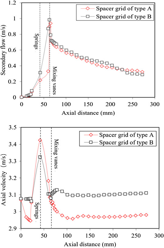
FIGURE 9. Distribution of velocity along axial direction for different types of the spacer grid.
As shown in Figure 10, for the type-A grid, the trends of the secondary flow in the two middle sub-channels are the same, and both of them have smaller secondary flow before 12Dh downstream of the grid than that of the type-B grid, while it is larger in the latter half downstream of the grid than in the type-B grid. Such a trend is consistent with that of the cross-sectional secondary flow. Although the decay rate of the type-A grid is greater in the middle section downstream of the grid in the corner channel, the secondary flow is still greater in the latter half of the downstream section of the grid than in the type-B grid. The same trend can be seen in the secondary flow variation near the fuel rods, where the trend of the type-A grid is larger than that of the type-B grid in all the latter half of the downstream parts of the grid. Based on the analysis of the changing trend of the secondary flow on the surface of fuel rod 21 and fuel rod 25, the difference of the secondary flow after 12Dh is strong due to the different guidance of the mixing vanes. Therefore, the influence distance of the type-A grid downstream of the grid is farther than that of the type-B grid, which might be associated with the direction of the induced secondary flow and the effect of the casing tube. In summary, the mixing vane leads to strong secondary flow. The arrangement and guidance of different mixing vanes have a great impact on the secondary flow downstream of the grid. The patterns of secondary flow between the same sub-channels are different, but the change trends are consistent with the cross-sectional average one. The secondary flow can maintain larger values at locations further from the grid, but the distance of influence is limited, which will have an important impact on the suppression of boiling crisis occurrence.
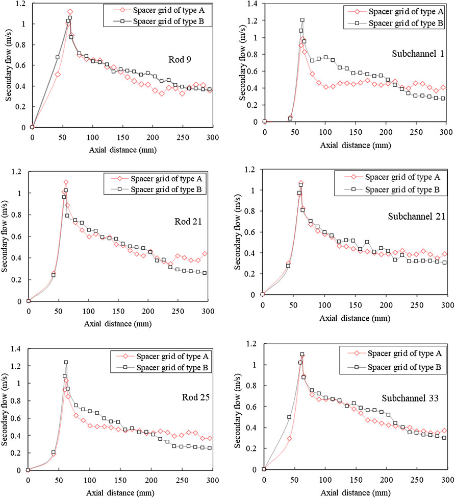
FIGURE 10. Distribution of secondary flow along axial direction in the sub-channel and around the fuel rod.
The variation of the secondary flow directly affects the degree of vapor phase accumulation on the fuel rod surfaces. Since the secondary flow has a large effect on the vapor phase distribution and a limited effect on the average void fraction at the cross-section, the difference in the average void fraction distribution between the two types of grids is small upstream of the spacer grid and inside the grid. However, for different fuel rod surfaces, the degree of vapor accumulation is different due to the influence of different secondary flows around the fuel rods. As shown in Figures 11, 12, the void fraction distribution of the two types of the grid shows different changes, especially at the top of the mixing vane. The vapor phase of the type-A grid is more concentrated in the center of the channel, while the vapor phase of the type-B grid is concentrated on the surface of the fuel rod and the vapor phase accumulation is more pronounced at 18Dh. In contrast, the secondary flow of the type-A grid does not decay significantly after 12Dh, so the vapor phase distribution on the fuel rod surface is more uniform at the 18Dh position. To deeply analyze the vapor phase distribution characteristics downstream of the two grids, the void fraction of different fuel rods and sub-channels of the two types of grids were compared and analyzed. It can be seen from Figure 13 that the void fraction increases gradually in the flow direction, both in the sub-channels and around the fuel rods. However, since the secondary flow of the type-B grid is smaller than that of the type-A grid, its void fraction is overall larger than that of the type-A grid, and such a trend is consistent with the variation of the average void fraction of the cross section along the flow direction. Through the analysis of the void fraction of different sub-channels, it can be seen that whether the sub-channel or the fuel rod surface is selected as the analysis object, and there is no difference in the variation trend of the void fraction.
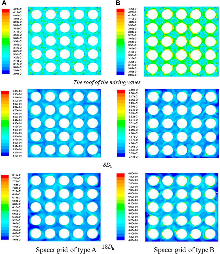
FIGURE 11. Variations of vapor-phase distribution at different axial cross sections.
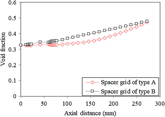
FIGURE 12. Average void fraction of cross sections along axial direction.
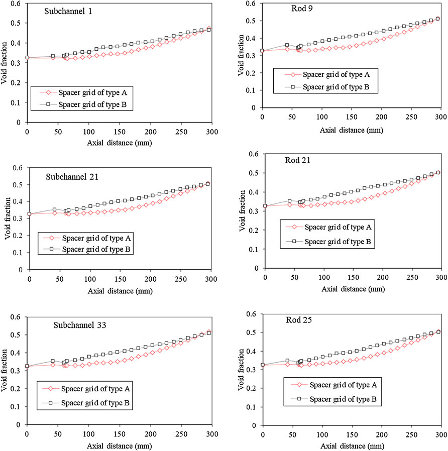
FIGURE 13. Average void fraction of cross sections in the sub-channel and around the fuel rod along axial direction for different spacer grids.
In this article, a multiphase flow model coupling boiling model based on thermal equilibrium was applied to investigate the two-phase flow characteristics in a 5 × 5 rod bundle with a spacer grid. The analysis of secondary flow and vapor phase distribution at different axial positions was carried out, including sub-channels, fuel rod surface, and cross sections. The main conclusions are listed as follows:
• The secondary flow is mainly caused by mixing vanes; the springs and dimples can induce a secondary flow of about 0.25 m/s, and the difference of secondary flow before and after the grid is about 0.64 m/s. The intensity and flow direction of secondary flow lead to the different distribution of the vapor phase on the fuel rod surface. Furthermore, the uniformity of secondary flow also has a great influence on the vapor accumulation of the fuel rod surface.
• Comparing two different types of spacer grids, the secondary flow of the type A spacer grid is greater after 12Dh than that of the type B spacer grid both in the sub-channel and around the fuel rod. The vapor phase of the type B spacer grid is easier to accumulate on the surface of fuel rods, and the average void fraction of the type A spacer grid is generally less than that of the type B spacer grid.
The original contributions presented in the study are included in the article/Supplementary Material, further inquiries can be directed to the corresponding authors.
YX: numerical simulation and writing. TD: numerical simulation, data processing, and writing—draft manuscript. Q-YR: writing—reviewing and supervision. XY-Z: data processing and writing—editing. MZ: manuscript editing. RH: data processing.
The authors are grateful for the support of the Natural Science Foundation of China (Grant No. 12105273) and the Fundamental Research Funds for the Central Universities (Nos Q2020-011, J2020-001 and ZJ 2021-08).
The authors declare that the research was conducted in the absence of any commercial or financial relationships that could be construed as a potential conflict of interest.
All claims expressed in this article are solely those of the authors and do not necessarily represent those of their affiliated organizations, or those of the publisher, the editors, and the reviewers. Any product that may be evaluated in this article, or claim that may be made by its manufacturer, is not guaranteed or endorsed by the publisher.
Agbodemegbe, V. Y., Cheng, X., Akaho, E. H. K., and Allotey, F. K. A. (2016). An Investigation of the Effect of Split-type Mixing Vane on Extent of Crossflow between Subchannels through the Fuel Rod Gaps. Ann. Nucl. Energ. 88, 174–185. doi:10.1016/j.anucene.2015.10.036
Agbodemegbe, V. Y., Cheng, X., Akaho, E. H. K., and Allotey, F. K. A. (2015). Correlation for Cross-Flow Resistance Coefficient Using STAR-CCM+ Simulation Data for Flow of Water through Rod Bundle Supported by Spacer Grid with Split-type Mixing Vane. Nucl. Eng. Des. 285, 134–149. doi:10.1016/j.nucengdes.2015.01.003
Anglart, H., and Nylund, O. (1996). CFD Application to Prediction of Void Distribution in Two-phase Bubbly Flows in Rod Bundles. Nucl. Eng. Des. 163 (1-2), 81–98. doi:10.1016/0029-5493(95)01160-9
Anglart, H., Nylund, O., Kurul, N., and Podowski, M. (1997). CFD Prediction of Flow and Phase Distribution in Fuel Assemblies with Spacers. Nucl. Eng. Des. 177 (1-3), 215–228. doi:10.1016/s0029-5493(97)00195-7
Arai, T., Furuya, M., Kanai, T., and Shirakawa, K. (2012). Development of a Subchannel Void Sensor and Two-phase Flow Measurement in 10×10 Rod Bundle. Int. J. multiphase flow 47, 183–192. doi:10.1016/j.ijmultiphaseflow.2012.07.012
Bakosi, J., Christon, M. A., Lowrie, R. B., Pritchett-Sheats, L. A., and Nourgaliev, R. R. (2013). Large-eddy Simulations of Turbulent Flow for Grid-To-Rod Fretting in Nuclear Reactors. Nucl. Eng. Des. 262, 544–561. doi:10.1016/j.nucengdes.2013.06.007
Busco, G., and Hassan, Y. A. (2018). Space and Energy-Based Turbulent Scale-Resolving Simulations of Flow in a 5 × 5 Nuclear Reactor Core Fuel Assembly with a Spacer Grid. Int. J. Heat Fluid Flow 71 (JUN), 420–441. doi:10.1016/j.ijheatfluidflow.2018.04.003
Caraghiaur, D., Anglart, H., and Frid, W. (2009). Experimental Investigation of Turbulent Flow through Spacer Grids in Fuel Rod Bundles. Nucl. Eng. Des. 239 (10), 2013–2021. doi:10.1016/j.nucengdes.2009.05.029
Carlucci, L. N., Hammouda, N., and Rowe, D. S. (2004). Two-phase Turbulent Mixing and Buoyancy Drift in Rod Bundles. Nucl. Eng. Des. 227 (1), 65–84. doi:10.1016/j.nucengdes.2003.08.003
Chen, D., Xiao, Y., Xie, S., Yuan, D., Lang, X., Yang, Z., et al. (2016). Thermal-hydraulic Performance of a 5 × 5 Rod Bundle with Spacer Grid in a Nuclear Reactor. Appl. Therm. Eng. 103, 1416–1426. doi:10.1016/j.applthermaleng.2016.05.028
Chen, S. R., Lin, W. C., Ferng, Y. M., Chieng, C. C., and Pei, B. S. (2014). CFD Simulating the Transient thermal-hydraulic Characteristics in a 17 × 17 Bundle for a Spent Fuel Pool under the Loss of External Cooling System Accident. Ann. Nucl. Energ. 73, 241–249. doi:10.1016/j.anucene.2014.06.054
Cho, H. K., Choi, K. Y., Cho, S., and Song, C.-H. (2011). Experimental Observation of the Droplet Size Change across a Wet Grid Spacer in a 6×6 Rod Bundle. Nucl. Eng. Des. 241 (12), 4649–4656. doi:10.1016/j.nucengdes.2011.03.042
Cinosi, N., Walker, S. P., Bluck, M. J., and Issa, R. (2014). CFD Simulation of Turbulent Flow in a Rod Bundle with Spacer Grids (MATIS-H) Using STAR-CCM+. Nucl. Eng. Des. 279, 37–49. doi:10.1016/j.nucengdes.2014.06.019
Conner, M. E., Hassan, Y. A., and Dominguez-Ontiveros, E. E. (2013). Hydraulic Benchmark Data for PWR Mixing Vane Grid. Nucl. Eng. Des. 264, 97–102. doi:10.1016/j.nucengdes.2012.12.001
Dominguez-Ontiveros, E. E., Hassan, Y. A., Conner, M. E., and Karoutas, Z. (2012). Experimental Benchmark Data for PWR Rod Bundle with Spacer-Grids. Nucl. Eng. Des. 253, 396–405. doi:10.1016/j.nucengdes.2012.09.003
Dominguez-Ontiveros, E., Estrada-Perez, C., and Hassan, Y. (2009). “Non-intrusive Experimental Investigation of Flow Behavior inside a 5x5 Rod Bundle with Spacer Grids Using PIV and MIR,”International Conference On Nuclear Engineering, 351–360.
Dominguez-Ontiveros, E., and Hassan, Y. A. (2014). Experimental Study of a Simplified 3×3 Rod Bundle Using DPTV. Nucl. Eng. Des. 279, 50–59. doi:10.1016/j.nucengdes.2014.04.037
Fen Shen, Y., Dong Cao, Z., and Gang Lu, Q. (1991). An Investigation of Crossflow Mixing Effect Caused by Grid Spacer with Mixing Blades in a Rod Bundle. Nucl. Eng. Des. 125 (2), 111–119. doi:10.1016/0029-5493(91)90071-o
Han, S. Y., Seo, J. S., Park, M. S., and Choi, Y. D. (2009). Measurements of the Flow Characteristics of the Lateral Flow in the 6×6 Rod Bundles with Tandem Arrangement Vanes. Nucl. Eng. Des. 239 (12), 2728–2736. doi:10.1016/j.nucengdes.2009.09.026
Khan, I., Wang, M., Zhang, Y., Tian, W., Su, G., and Qiu, S. (2020). Two-phase Bubbly Flow Simulation Using CFD Method: A Review of Models for Interfacial Forces. Prog. Nucl. Energ. 125, 103360. doi:10.1016/j.pnucene.2020.103360
Lin, C.-H., Yen, C.-H., and Ferng, Y.-M. (2014). CFD Investigating the Flow Characteristics in a Triangular-Pitch Rod Bundle Using Reynolds Stress Turbulence Model. Ann. Nucl. Energ. 65, 357–364. doi:10.1016/j.anucene.2013.11.023
Liu, C. C., and Ferng, Y. M. (2010). Numerically Simulating the thermal-hydraulic Characteristics within the Fuel Rod Bundle Using CFD Methodology. Nucl. Eng. Des. 240 (10), 3078–3086. doi:10.1016/j.nucengdes.2010.05.021
Liu, M., and Ishiwatari, Y. (2013). Unsteady Numerical Simulations of Single-phase Turbulent Mixing in Tight Lattice Geometries. Nucl. Eng. Des. 256, 28–37. doi:10.1016/j.nucengdes.2012.11.008
Liu, W., Liu, Y., Peng, S., Jiang, G., Liu, Y., Li, J., et al. (2021). Visualization of Spacer Grid Effect on Bubble Behavior and CHF in a Single-Rod Channel. Nucl. Eng. Des. 382, 111376. doi:10.1016/j.nucengdes.2021.111376
McClusky, H. L., Holloway, M. V., Beasley, D. E., and Conner, M. E. (2002). Development of Swirling Flow in a Rod Bundle Subchannel. J. Fluids Eng. 124 (3), 747–755. doi:10.1115/1.1478066
Navarro, M. A., and Santos, A. A. C. (2011). Evaluation of a Numeric Procedure for Flow Simulation of a 5 × 5 PWR Rod Bundle with a Mixing Vane Spacer. Prog. Nucl. Energ. 53 (8), 1190–1196. doi:10.1016/j.pnucene.2011.08.002
Pham, S. H., Kawara, Z., Yokomine, T., and Kunugi, T. (2014). Detailed Observations of Wavy Interface Behaviors of Annular Two-phase Flow on Rod Bundle Geometry. Int. J. multiphase flow 59, 135–144. doi:10.1016/j.ijmultiphaseflow.2013.11.004
Pham, S. H., Kawara, Z., Yokomine, T., and Kunugi, T. (2015). Measurements of Liquid Film and Droplets of Annular Two-phase Flow on a Rod-Bundle Geometry with Spacer. Int. J. Multiphase Flow 70, 35–57. doi:10.1016/j.ijmultiphaseflow.2014.11.010
Podila, K., and Rao, Y. (2016). CFD Modelling of Turbulent Flows through 5 × 5 Fuel Rod Bundles with Spacer-Grids. Ann. Nucl. Energ. 97, 86–95. doi:10.1016/j.anucene.2016.07.003
Rehme, K. (1989). Experimental Observations of Turbulent Flow through Subchannels of Rod Bundles. Exp. Therm. Fluid Sci. 2 (3), 341–349. doi:10.1016/0894-1777(89)90023-x
Rehme, K. (1987). The Structure of Turbulent Flow through Rod Bundles. Nucl. Eng. Des. 99, 141–154. doi:10.1016/0029-5493(87)90116-6
Ren, Q.-Y., Pan, L.-M., Pu, Z., Zhu, F., and He, H. (2021). Two-group Phase Distribution Characteristics for Air-Water Flow in 5 × 5 Vertical Rod Bundle Channel with Mixing Vane Spacer Grids. Int. J. Heat Mass Transfer 176, 121444. doi:10.1016/j.ijheatmasstransfer.2021.121444
Ren, Q., Pan, L., Zhou, W., Ye, T., and Li, S. (2018b). Comparison of Drift-Flux Models for Void Fraction Prediction in Sub-channel of Vertical Rod Bundles. 26th International Conference On Nuclear Engineering. doi:10.1115/icone26-81435
Ren, Q-y., Zhou, W-x., Si-jia, D., Zhong-chun, Li., and Pan, L-m. (2018a). Sub-channel Flow Regime Maps in Vertical Rod Bundles with Spacer Grids. INTERNATIONAL JOURNAL HEAT. MASS TRANSFER 122, 1138–1152. doi:10.1016/j.ijheatmasstransfer.2018.01.133
Wang, M., Wang, Y., Tian, W., Qiu, S., and Su, G. H. (2021). Recent Progress of CFD Applications in PWR thermal Hydraulics Study and Future Directions. Ann. Nucl. Energ. 150, 107836. doi:10.1016/j.anucene.2020.107836
Wang, Y., Wang, M., Ju, H., Zhao, M., Zhang, D., Tian, W., et al. (2020). CFD Simulation of Flow and Heat Transfer Characteristics in a 5×5 Fuel Rod Bundles with Spacer Grids of Advanced PWR. Nucl. Eng. Technol. 52 (7), 1386–1395. doi:10.1016/j.net.2019.12.012
Wu, X., and Trupp, A. C. (1993). Experimental Study on the Unusual Turbulence Intensity Distributions in Rod-To-wall gap Regions. Exp. Therm. Fluid Sci. 6 (4), 360–370. doi:10.1016/0894-1777(93)90014-a
Xiong, J., Qu, W., Zhang, T., Chai, X., Liu, X., and Yang, Y. (2020). Experimental Investigation on Split-Mixing-Vane Forced Mixing in Pressurized Water Reactor Fuel Assembly. Ann. Nucl. Energ. 143, 107450. doi:10.1016/j.anucene.2020.107450
Yang, P., Zhang, T., Hu, L., Liu, L., and Liu, Y. (2021). Numerical Investigation of the Effect of Mixing Vanes on Subcooled Boiling in a 3 × 3 Rod Bundle Channel with Spacer Grid. Energy 236, 121454. doi:10.1016/j.energy.2021.121454
Yang, S.-K., and Chung, M.-K. (1996). Spacer Grid Effects on Turbulent Flow in Rod Bundles. Nucl. Eng. Technol. 28 (1), 56–71.
Yang, S. K., and Chung, M. K. (1998). Turbulent Flow through Spacer Grids in Rod Bundles, J. Fluids Eng. 120, 786–791. 10.1115/1.2820739.
Zhang, J., Wang, M., Chen, C., Tian, W., Qiu, S., and Su, G. H. (2022). CFD Investigation of the Cold wall Effect on CHF in a 5 × 5 Rod Bundle for PWRs. Nucl. Eng. Des. 387, 111589. doi:10.1016/j.nucengdes.2021.111589
Keywords: spacer grid, boiling two-phase flow, void fraction, sub-channels, CFD
Citation: Xiao Y, Duan TC, Ren Q-Y, Zheng X-Y, Zheng M and He R (2022) Modeling and Simulation Analysis on Mixing Characteristics of Two-Phase Flow Around Spacer Grid. Front. Energy Res. 10:891074. doi: 10.3389/fenrg.2022.891074
Received: 07 March 2022; Accepted: 06 April 2022;
Published: 12 May 2022.
Edited by:
Mingjun Wang, Xi’an Jiaotong University, ChinaReviewed by:
Luteng Zhang, Chongqing University, ChinaCopyright © 2022 Xiao, Duan, Ren, Zheng, Zheng and He. This is an open-access article distributed under the terms of the Creative Commons Attribution License (CC BY). The use, distribution or reproduction in other forums is permitted, provided the original author(s) and the copyright owner(s) are credited and that the original publication in this journal is cited, in accordance with accepted academic practice. No use, distribution or reproduction is permitted which does not comply with these terms.
*Correspondence: Y. Xiao, eGlhb3lpX2NhZnVjQGZveG1haWwuY29t; Quan-Yao Ren, cmVucXVhbnlhb0Bmb3htYWlsLmNvbQ==
Disclaimer: All claims expressed in this article are solely those of the authors and do not necessarily represent those of their affiliated organizations, or those of the publisher, the editors and the reviewers. Any product that may be evaluated in this article or claim that may be made by its manufacturer is not guaranteed or endorsed by the publisher.
Research integrity at Frontiers
Learn more about the work of our research integrity team to safeguard the quality of each article we publish.