 Ashley Willow
 Haytham E. M. Hussein1
 Sutthiphan Vajirakaphan
 Aphidet Chasri
 Serena Margadonna
- 1Future Manufacturing Research Institute, Faculty of Science and Engineering, Swansea University, Swansea, United Kingdom
- 2Enserv Power Co., Ltd, Enserv Innovation Centre, Bangkok, Thailand
Herein we report key developments on the scale-up of sodium ion anode free batteries through investigation of the effects of applied external pressure cell performance. Sodium ion anode free puts extra emphasis on high plating and stripping efficiency of sodium metal at the anode surface, due to the lack of an excess of the transporting ion. We demonstrate excellent Na||Cu half-cell results in coin cell configuration, and the scalability of the anode-free concept is further demonstrated, by plating and stripping of sodium metal on copper foils 10-fold larger (>10 cm 2) than in other studies in coin cells (∼1 cm2). It is discovered that pressure is paramount in establishing dendrite free sodium deposition at this scale through investigating the half-cell cycling at 56–743 kPa. Achieving a low hysteresis in these large-area cells is found to only require moderate pressures (∼185 kPa). However, achieving a high cycle life required increasing the pressure to 743 kPa. It is only at these high pressures that non-dendritic sodium deposition is demonstrated due to a homogeneous plating distribution enabled by proper contact between electrodes, as confirmed by impedance measurements and optical imaging of the deposited sodium.
Introduction
Anode-free sodium-ion batteries differ from traditional sodium ion batteries in the anode process. Upon charging, traditional sodium ion batteries involve insertion of the transporting ion into the negative electrode material. Instead, the anode-free technology is based on in-situ plating and stripping of sodium metal directly on the current collector. As there is a complete removal of the anode active material, the anode free configuration brings significant advantages in terms of increased energy densities coupled with reduced costs and simplified manufacturing. However, for large scale deployment and commercialization of the technology, the batteries are to exhibit cycle life greater than or equal to standard sodium ion batteries. In recent years, research efforts focused on improving the cyclability of anode-free sodium-ion batteries from the perspective of various cell components: cathode, negative substrate, electrolyte, and cell assembly.
Up to now, anode-free sodium ion batteries have been demonstrated with only a limited number of cathode materials: for example, presodiated FeS2 (Cohn et al., 2017), Na3V2(PO4)3 (NVP) (Ma et al., 2021), presodiated Prussian blue (Mazzali et al., 2019), Prussian white (Wang et al., 2021), monoclinic Prussian blue analogues (Rudola et al., 2017a; Rudola et al., 2017b) and pre-sodiated Na1.5VPO4.8F0.7 (Lee et al., 2019). Prussian blue analogues and NVP show promise due to their high capacities without the requirement for presodiation in half cells. Prussian blue analogues are also promising as they have seen commercial implementation in standard sodium ion batteries due to their low-cost and long cycle life (Wang T. et al., 2018; Lyu et al., 2019).
Key for the technology are the substrates on which the plating and stripping processes occur. A variety of substrates have been investigated, mainly in half cell Na||substrate format, with some full cell studies. For example, carbon-coated aluminum (Cohn et al., 2017; Mazzali et al., 2019), a silver nanofiber@nitrogen-rich carbon thin layer core–shell material, (Lee et al., 2019), copper (Ma et al., 2021), oxygen-doped carbon nanotubes (Chu et al., 2019), group II metals (Zhu et al., 2019) and gold-coated copper (Tang et al., 2018). Copper as a substrate is promising due to its exceptional coulombic efficiency at a range of current densities, providing the water content of electrolyte is controlled (Ma et al., 2021). Copper foil demonstrates a lower nucleation overpotential than aluminum when unmodified (Zhu et al., 2019). It requires minimal preparation other than a clean surface and as it has the advantage of not requiring a nucleation layer, therefore simplifying battery production. Other promising results include the use of aluminum with a carbon nucleation layer to reduce plating hysteresis and nucleation overpotential (Cohn et al., 2017). This will have weight advantages over copper and therefore would impart a higher gravimetric energy density when used in full cells.
1M NaPF6 in diglycol methyl ether (diglyme) electrolyte is the de facto electrolyte in most studies due to its stability to sodium metal (Westman et al., 2018) and high coulombic efficiency when used in Na||Na cells compared to carbonate-based electrolytes and glymes containing other salts (Seh et al., 2015). If the water content is controlled to <10 ppm, remarkable rate capability can be observed in this electrolyte (Ma et al., 2021) in Na||Cu cells, which is a half-cell relevant to sodium-ion anode-free technology. However, due to the lack of exploration in this area, there is scope for further investigations into the electrolyte used in sodium anode-free batteries, as most studies were performed in Na||Na symmetrical cells for sodium metal battery applications. Examples of potential optimization that could be applied revolve around electrolyte concentration (as has been investigated for sodium metal batteries (Cao et al., 2016)), addition of additives to the efficient NaPF6/diglyme system (as has been investigated by the addition of sodium polysulfides in Na-S cells (Wang H. et al., 2018)) and reducing the water content in other electrolytes (as a stable Na||Na interface has been observed in carbonate electrolytes, if the water content is reduced to <10 ppm (Conder and Villevieille, 2019)).
To optimize anode-free systems, it is also essential to understand the effects of cell configuration and assembly on the plating and stripping mechanism. Research in the field of lithium-ion anode-free technology shows that applied pressure on the cell stack plays an important role for enhancement of cycle-life in full and half-cell configurations (Louli et al., 2019; Zhou et al., 2021). At coin cell level, it has been shown that by incorporating an extra spacer, which has the effect of increasing pressure in the cell, a lower impedance for lithium plating on copper can be observed along with dendrite free lithium deposits. Furthermore, the extra spacer greatly increases coulombic efficiency and cycle life (Zhou et al., 2021). The positive effects of pressure have also been demonstrated at larger, pouch-cell formats; where optimal applied external pressure can increase cycle life and improve the morphology of the plated Li-metal on the copper substrate (Louli et al., 2019). The greatest benefits in this study were found at the applied pressure of 1,200 kPa.
From these results, it is evident that applied pressure influences cell performance and morphology of the deposits. Further studies are therefore needed, particularly for sodium-ion free batteries where the effects of pressure are largely unexplored. This work investigates the impact of applied pressure on the sodium plating in Na||Cu half cells at areas larger than in coin cells using a split pouch cell configuration. We focus on the split pouch cell to bridge the gap in research between the small-scale coin cells and the large-format pouch cells, to explore conditions and parameters that are more relevant to real-world applications and commercialization.
Materials and Methods
Coin Cell Assembly and Electrolyte
316 stainless steel coin cells (Cambridge Energy Solutions Ltd.) were assembled in an MBraun glovebox (H2O < 0.1ppm and O2 < 0.5ppm) in the CR2032 format, using 1.5 mm thickness spacers, a cone spring and a Celgard 2325 separator cut to 20 mm diameter. The separator was dried at 60 Celsius for 24 h prior to transferring to the glovebox. Copper foil was used as a working electrode, cut to 15 mm, and rinsed with dry hexane (Merck) in the glovebox prior to use in the cell. Sodium (Merck) cubes, were removed from mineral oil in the glovebox, washed with dry hexane, trimmed of their oxidized edges with a scalpel, rolled between sheets of laminated pouch material, scored, and cut to 12 mm diameter before use in the coin cell as the counter electrode. Our handling of sodium ensured a homogeneous surface, free of surface pollutants, as has been described previously (Conder and Villevieille, 2019). The final cell assembly was sealed at 75 kg cm−2 in a crimping machine (Cambridge Energy Solutions) whilst containing 40 µl of electrolyte (preparation below).
1M NaPF6 in diglyme electrolyte was prepared in the following way. NaPF6 (Alfa Aesar 99+%) was dried under argon at 150 Celsius for 24 h. Diglyme (anhydrous, 99.5%, Merck) was dried further over molecular sieves until <10ppm water is observed as measured by Karl Fischer (Mettler Toledo, Titrator Compact C10SD). Dried NaPF6 was dissolved in dried diglyme and the water content measured again. If needed, molecular sieves were added until the water content for the final electrolyte was <10 ppm. We found that controlling the water content in this way led to reliably reproducible results in both coin cell and split pouch cell formats, likely due to a reduction in the occurrence of side reactions and sodium passivation (Conder and Villevieille, 2019; Ma et al., 2021).
Split Pouch Cells and Pressure Controlled Studies
For the split pouch cell work, a pressure controlled split pouch cell (EQ-PSPC MTI Corporation) was used. This cell was designed for solid state battery research but has been adapted for use in this work. Firstly, a PEEK alternative to the Nylon chamber was machined in-house for chemical resistance. The internal chamber has dimensions of 58 × 45 × 4 mm (length x width x depth). As the depth of the chamber is much larger than a single Na||Cu cell (copper, separator and sodium <200 µm), spacers, made of stainless steel were machined to fill the depth of the cell. A single large 3 mm spacer and two smaller 0.5 mm spacers were machined to investigate the effect of spacer thickness on cycling. The cell also contained a 150 µm stainless steel wave plate (of thickness 150 µm), which flattens on compression during assembly. The cell stack was therefore assembled as follows, from bottom to top; bottom plate, PEEK chamber (with sealing ring), copper, separator, sodium, 3 mm spacer + (0,1 or 2) 0.5 mm spacer(s), wave spring, top plate (in contact with the top sealing ring). The assembly mimics a coin cell in construction but offers a ten-fold increase in area that can be studied. The cells seals with an o-ring and pressure applied by placing the split pouch cell within a mechanical jig (MTI Corporation), evenly tightening the bolts with a torque wrench. The compressive force during assembly was measured with a pressure calibration unit (MTI Corporation) and converted to pressure. Copper and sodium were prepared as described above, with dimensions noted in the results section below. An illustration of the split pouch cell, a cell cross section and the mechanical jig, are shown in Figures 1A–D.
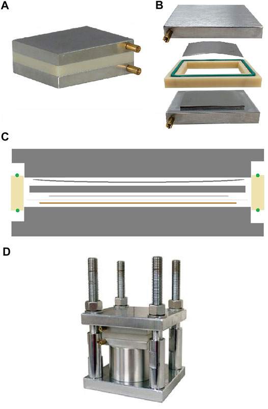
FIGURE 1. (A) Split pouch cell used in this study. (B) expanded view of the split pouch cell without the spacers and Na||Cu cell. (C) Illustration of the Cross section of the split pouch cell, showing an example Na||Cu cell assembly. Bottom to top: bottom plate, PEEK chamber (with sealing ring), copper, separator, sodium, 3 mm spacer + (0, 1 or 2) 0.5 mm spacer(s), wave spring, top plate (in contact with the top sealing ring). (D) Split pouch cell situated within the mechanical jig used to apply pressure. Images (A), (B) and (D) are reproduced with permission of MTI Corporation.
Initial studies on the application of pressure were performed by modifying the spacer thickness, without measuring the force applied with the pressure calibration unit. The bolts of the mechanical jig were hand-tightened to the same degree (later estimated to be about 185 kPa) whilst varying the spacer thickness. At 3, and 3.5 mm of spacer thickness the wave spring is partially compressed, and part of the pressure is imparted to the Na||Cu half-cell (pressure increases with spacer thickness). At 4 mm of thickness the depth of the chamber is filled, the spring fully compressed, and the full pressure applied to the Na||Cu half-cell.
Accurate studies on the effect of pressure were performed by fixing a total spacer thickness of 4 mm, fully compressing the wave spring, and adjusting and measuring the applied pressure with the pressure calibration unit. The pressure for each experiment is noted in the results section and varies between 30 and 400 kg. For comparison to other studies on the effect of pressure on lithium metal anode free cells (Louli et al., 2019), we have converted the readout from the pressure calibration unit, which is in kg, to kPa pressure here by taking into account the weight distributed over the whole split pouch cell area. 30, 40, 55, 85, 100, 200 and 400 kg were used, which equates to a pressure 56, 76, 102, 158, 185, 371, 743 kPa respectively and shall be used throughout the rest of this article.
Battery Cycling and Electrochemical Impedance Spectroscopy
Galvanostatic charge-discharge cycling was performed on coin cells in a Basytec system and split pouch cells on an Astrol BATSMALL. After assembly in the glovebox, cells were removed and left at open circuit for 6 h prior to cycling. Exact cycling conditions are referenced in the results section, as they vary per experiment. Electrochemical impedance spectroscopy (EIS) was carried out on an OctoStat30.
Cell Disassembly and Optical Imaging
The split pouch cell was disassembled in a glovebox by loosening the bolts of the mechanical jig and removing the split pouch cell assembly. The split pouch cell design enabled simple disassembly after cycling by removing the top plate, springs, and spacers. The cells were disassembled after plating to evaluate the plating morphology optically. The sodium plated copper was removed from the cell before cutting and sealing between glass slides using vacuum grease and epoxy glue to protect the sample from exposure to ambient air when outside the glovebox. Samples were imaged using a ZEISS Smartzoom 5 automated digital optical microscope.
Results and Discussion
Na Plating on Copper in Coin Cells
Before performing pressure studies at large areas in split pouch cells, Na||Cu half-cells were made in coin cell format for comparison. It is worth mentioning that the internal mechanical pressure in a coin cell is not well defined and controlled. It has been shown that the force within a coin cell can be estimated through measuring compression of the spring, where the force may range from 87 to 279N when different numbers of springs are used (Stoller et al., 2011). This would equate to a pressure of 277–888 kPa when the area of the coin cell is considered. However, the spring type (Belleville or conical) is not known, which would have a considerable effect on the pressure.
In our coin cell studies, two current densities were evaluated, 0.5 and 0.2 mA cm−2 with an areal capacity of 0.25 and 0.1 mAh cm−2 respectively and a voltage limit of 500 mV to unsure complete stripping at each cycle. The coulombic efficiency (CE) was calculated as the ratio of the variable capacity during charge and the fixed charge passed during discharge. This is shown for both applied currents in Figure 2A. The CE is very similar for both currents in the early stages of cycling, with the 0.5 mA cm−2 cycling showing higher efficiency than 0.2 mA cm−2 in the first 200 cycles (99.93 vs. 99.90% respectively). As cycling progresses, the performance of the different current density cells diverges. The cell cycled at 0.5 mA cm−2 drops to 99.80% after approximately 340 cycles. Whereas the 0.2 mA cm−2 cell takes ∼1,000 cycles to drop to the same CE. The increase in cycle life, ∼2.9x, is slightly greater but comparable to the difference in current density, 2.5x, between the 2 cells and therefore is expected. Figure 2B illustrates the complete stripping of copper in the first 100 cycles of both current densities. The plating and stripping hysteresis can be seen in Figure 2C to be ∼20 mV for 0.5 mA cm−2 and 10 mV at 0.2 mA cm−2. The nucleation overpotential, as shown in Figure 2C, only slightly increases from 40 to ∼43mV upon increasing the current density.
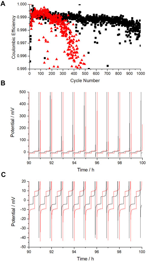
FIGURE 2. (A) Coulombic efficiency of Na||Cu cells cycled at two current densities in coin cell format, 0.5 and 0.2 mA cm−230-min cycling (0.25 and 0.1 mAh cm−2). (B) voltage-time at 90–100 h emphasizing the complete stripping of sodium. (C) voltage time graph focusing on the plating-stripping hysteresis and nucleation overpotential. 0.5 mA cm−2 cycling is shown in red and 0.2 mA cm−2 cycling in black.
Split Pouch Cell Format—The Effect of Spacers
The split pouch cells described here were assembled with copper 40 × 40 mm and sodium cut to 35 × 35 mm. The separator had dimensions of 45 × 45 mm. The area of sodium used is 12.25 cm−2 and therefore more than 10-times higher than that used in the coin cell study (1.13 cm−2). Cells were assembled with 3, 3.5 and 4 mm of spacers, with the mechanical jig tightened to the same amount (until the washers just compressed in the mechanical jig assembly). This was later evaluated with a pressure calibration unit to be ∼185 kPa. It is expected from previous work on lithium metal (Zhou et al., 2021) that increasing the spacers will improve coulombic efficiency and may reduce SEI thickness. It is not known whether an upper limit exists for the positive effects of pressure on lithium (or sodium) plating on copper.
Due to the design of the cell used, the Na||Cu half-cell experiences an increasing proportion of the full, 185 kPa, pressure with increasing spacer thickness. It is only when the chamber is filled with 4 mm spacers that the full 185 kPa is applied to the half cell. This study served as an initial test to see if pressure had a considerable effect in Na||Cu half cells and to justify more accurate investigations into the effect of pressure detailed in the next section.
Figure 3 shows that increasing the compressive force by increasing the width of spacers had a positive effect on the plating performance, by reducing the voltage hysteresis and improving cycling stability at 0.2 mA cm−2 in Figures 3A, 0.5 mA cm−2 in Figure 3B. The unstable potential when a 3 or 3.5 mm spacer is expected to be an issue of poor contact in the Na||Cu half-cell, which results in high plating and stripping overpotential (hysteresis) and expected dendritic sodium growth. Figure 3C shows that by optimizing the spacer thickness in the split pouch cell format the hysteresis observed at coin cell level can be matched, at least for the first 80 cycles, after which the hysteresis of the 2 cells diverges. Cell performance deteriorates significantly at > 180 cycles in split pouch cell format, whereas the coin cell continues to consistently exhibit low plating and stripping hysteresis. It is clear from these results that the pressure experienced by the Na||Cu half-cell has a significant impact on hysteresis and that further optimization of this parameter could bridge the cycle life gap between coin cell and split pouch cell formats. From these initial studies it was expected that >185 kPa would further benefit cycling performance.
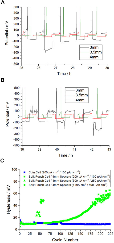
FIGURE 3. (A) Voltage-time graph of Na||Cu half cells in split pouch cell format with increasing spacer thickness focusing on the voltage hysteresis at 0.2 mA cm−2/0.1 mAh cm−2 (B), as before but with 0.5 mA cm−2/0.25 mAh cm−2 (C) Hysteresis throughout cycle life in pouch cell format at 0.2 mA cm−2/0.1 mAh cm−2 using 4 mm of spacers vs. coin cell.
Split Pouch Cell Format—Pressure Controlled Studies
To follow on from the work described above, the split pouch cell was assembled with a fixed spacer thickness of 4 mm, and the compressive jig tightened with a torque wrench. The pressure was calculated from the pressure calibration unit weight readouts. In this study a lower sodium area of 7 cm2 was used so that expansion due to compression of the sodium by the high pressures applied could be allowed for. The hysteresis vs. pressure is shown in Figures 4A–C. Initially the cell was sealed and cycled at 56 kPa, with the aim of cycling 20 cycles at 0.5 mA cm−2/0.25 mAh cm−2 at increasing pressure. At this pressure the cell exhibited very high overpotential for plating and stripping (high hysteresis of ca 250 mV), incomplete stripping of sodium and erratic voltage behavior indicative of dendritic growth. This issue was observed in the uncalibrated cells with insufficient spacers, discussed above. It was allowed to cycle for five cycles before the force was increased. A substantial improvement to the voltage hysteresis was seen upon increasing the force from 56 to 185 kPa (where Figure 4C shows the hysteresis to have decreased to 32 mV) and the cell was then allowed to cycle 20 times at each pressure between 185 and 743 kPa. Further increases in applied pressure, up to 743 kPa, saw only incremental improvements to the hysteresis which seems to level off at 22 mV, near the value observed in our coin cell study above.
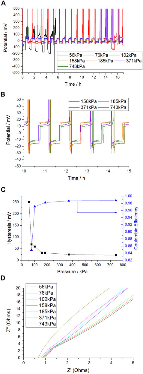
FIGURE 4. (A) Voltage-time graph of Na||Cu half cells in split pouch cell format with increasing applied pressure (spacer thickness fixed at 4 mm), 0.5 mA cm−2/0.25 mAh cm−2. (B) as previous but focusing on pressures >185 kPa only. (C) Hysteresis (and coulombic efficiency) vs. initial applied pressure. (D) As assembled EIS on increasing pressure. (10 mV perturbation, high frequency range from 40 to 1 khz shown).
Upon disassembly it was noticed that there was some compression of the sodium metal, which expanded the area of the sodium foil, increasing the effective surface area to an estimate of 9 cm2. This compression could be at least partially responsible for the small decrease in voltage hysteresis at pressures greater than 185 kPa, as the higher area would be responsible for a decrease in the effective current density. However, the changes observed at < 185 kPa are expected to not be caused by this effect and another cell was made to investigate the changes in hysteresis in this pressure range. The results shown in Figure 4 at pressures of 76, 102 and 158 kPa were made with a second cell and follow the same trend as reported for the first cell. It also shows that most of the benefit in hysteresis and cycling stability over a few cycles is gained by only small increases in pressure (from 76 to 102 or 158 kg). Coulombic efficiency however is very poor at <185 kPa, and >185 kPa is needed to approach coin cell level efficiency. As Figure 4C shows, coulombic efficiency is 85.97, 98 and 99% at 76, 102, 185 and 743 kPa respectively.
To understand the origins of improved electrochemical performance of cells cycled at higher pressures, EIS was performed on the as-assembled cells and the results are shown in Figure 4D. The main effect observed is a decrease in impedance at high frequency, in the electrolyte regime. As there is no actual change to the electrolyte, this must be caused by an increase in the effective area of sodium or decrease in the sodium-copper average distance when pressure is applied. Pressure is clearly improving the contact between the sodium and the separator during cell assembly, due to the reduction in solution resistance from 0.975 Ω at 56kPa to 0.65 Ω at 743kPa, indicating a greater area of sodium at a reduced distance from the copper substrate. This would be expected to lead to more homogeneous plating. Through inspection of the EIS there are also small changes that are due to charge transfer resistance, with a small reduction on increasing pressure. However, these are minor and secondary to those relative to the electrolyte resistance.
As 743 kPa showed a promising combination of hysteresis and coulombic efficiency in the initial screen, a new cell was made at this pressure and set to cycle at 0.2 mA cm−2/0.1 mAh cm−2 to compare to the results previously shown in Figure 3. This comparison is shown in Figure 5. Here it can be seen that the hysteresis at 743 kPa matches closely the results obtained in coin cell format and there is a great improvement over 185 kPa. At 743 kPa the voltage hysteresis begins to increase after 160 cycles, indicating that further optimizing may be possible to maintain low hysteresis over extended cycling.
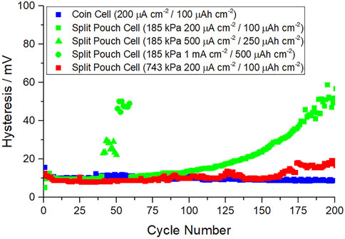
FIGURE 5. Na||Cu half-cell cycle life hysteresis in coin cell vs. split pouch cell format at two different applied pressures, 185 and 743 kPa.
Optical Imaging of Plating Morphology
Figure 6 shows optical imaging of plated sodium on copper at a capacity of 0.25 mAh cm−2 and a current of 0.5 mA cm−2. Three different pressures were chosen: 56, 158 and 743 kPa, representing the low, intermediate, and high pressures investigated in the electrochemical studies. As seen in Figure 4 the electrochemical performance improves greatly between these three values.
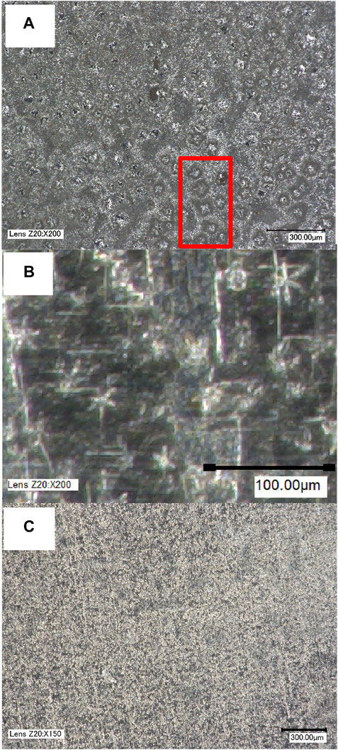
FIGURE 6. Optical imaging of sodium plated on copper after five cycles of plating and stripping (ending on plating at 0.5 mA/0.25 mA h) at (A) 56 kPa, (B) 158 kPa and (C) 743 kPa pressure. A group of needle-like growths at 56 kPa are highlighted in red in (A). At 158 kPa a higher zoom is used in (B).
Figure 6A shows that when sodium is plated under low pressure, large (50 µm) needle like and star-shaped growths can be observed throughout the surface. A number of these growths are highlighted in red. The number and size of these particles are expected to be responsible for the voltage instabilities observed in the galvanostatic experiments in Figure 4 due to the following reasons: the rapidity and fragility of this type of growth, its reactivity with electrolyte in forming new SEI and its ability to reduce the electrode-electrode distance, possibly penetrating the separator. Figure 6B shows that at intermediate pressure (158 kPa) the needle like growths are still present, but greatly reduced in size (20 µm). The scale is of Figure 6B is therefore adjusted to emphasize these features. These features are visible throughout the surface and dispersed more homogeneously than at low pressure. Apart from these structures, sodium growth appears more conformal than at low pressure. At 743 kPa these growths are not observed, and the plated sodium is dispersed homogeneously over the surface of the copper. These results are in line with those reported for Li||Cu coin cells (Zhou et al., 2021), where the increase in compression afforded by an extra spacer eliminated these types of growths that were present when only one spacer was used.
Conclusion
The results described herein show the importance of the pressure experienced by the Na||Cu half-cell plays in plating and stripping of metallic sodium on a copper substrate. Demonstrated at a 10-fold increase in area over previous coin cell results, it also shows that pressure is a key factor to consider for the scale-up of the technology. Using a split pouch cell format, poor performance, in terms of hysteresis and coulombic efficiency, is shown when the pressure is < 185 kPa. Hysteresis and coulombic efficiency improve greatly between 56 and 185 kPa and level off at 185–743 kg. Even though initial cycling performance only shows minor improvements upon increasing pressure from 185 to 743 kPa, cycle life can be substantially improved in this pressure range: at 743 kPa, coin cell performance is maintained over 160 cycles, vs. 80 cycles 185 kPa. EIS results on as-assembled cells show a decrease in solution resistance upon increasing pressure, which we assign to a greater proportion of the sodium having good contact with the separator. Such an affect will be responsible for a homogeneous plating distribution over a larger area when the pressure is increased, explaining how the low hysteresis is maintained over many more cycles at 743 kPa. The improvements in cycling performance demonstrated here are in line with those reported in Li||Cu coin cells (Zhou et al., 2021), where an extra spacer in the coin cell improved coulombic efficiency and cycle life. However, it is shown here that Na||Cu half cells demonstrate much higher CE values than their lithium counterparts.
Optical imaging of cells after plating at low intermediate and high pressures shows that increasing the pressure can effectively reduce and eliminate needle-like, star-shaped-growth and is thought to be the mechanism for the improvement in electrochemical performance observed: with more homogeneous growth of sodium across the copper surface resulting in a lower surface area for side reactions and dynamic SEI formation. These optical image observations corroborate the EIS results as homogeneous plating is demonstrated visually at 743 kPa.
It may be expected that the positive effects of pressure shown here will extend to full cell configuration. However, pressure may affect the anode and cathode processes differently. For example, high pressures may result in blocked pores in the cathode structure. This implies that the cathode processes may benefit from increasing pressure up to a point, and that further pressure increases may be detrimental. This type of optimal pressure has been demonstrated in lithium anode free full cells using a FEC:TFEC electrolyte system (Louli et al., 2019) and performance deterioration was observed at high pressures due to increased polarization. These hypotheses will be investigated in follow up work by looking at the effect of pressure on cathode half-cells and full anode free sodium ion cells in the split pouch cell format.
Data Availability Statement
The raw data supporting the conclusion of this article will be made available by the authors, without undue reservation.
Author Contributions
AW conducted electrochemical experiments, analysed and interpreted the data, and wrote the manuscript. HH conducted optical imaging studies described and contributed to interpretation of data. SM conceptualised the study, contributed to experimental design and interpretation of data and oversaw the project. SV and AC provided advise and feedback to the experiments, interpretation of data and manuscript feedback.
Funding
This study is partially funded by Enserv Power Co. Ltd. This research contributes to the IMPACT operation which has been part-funded by the European Regional Development Fund through the Welsh Government and Swansea University. The funder had the following involvement with the study: through these authors, provided advise and feedback to the experiments, interpretation of data and manuscript feedback.
Conflict of Interest
Author SV and AC are employed by Enserv Power Co. Ltd.
The remaining authors declare that the research was conducted in the absence of any commercial or financial relationships that could be construed as a potential conflict of interest.
Publisher’s Note
All claims expressed in this article are solely those of the authors and do not necessarily represent those of their affiliated organizations, or those of the publisher, the editors and the reviewers. Any product that may be evaluated in this article, or claim that may be made by its manufacturer, is not guaranteed or endorsed by the publisher.
Acknowledgments
The authors acknowledge the use of the facilities within the Future Manufacturing Research Institute, Faculty of Science and Engineering, Swansea University, for electrochemical characterization and optical imaging.
References
Cao, R., Mishra, K., Li, X., Qian, J., Engelhard, M. H., Bowden, M. E., et al. (2016). Enabling Room Temperature Sodium Metal Batteries. Nano Energy 30, 825–830. doi:10.1016/j.nanoen.2016.09.013
Chu, C., Wang, N., Li, L., Lin, L., Tian, F., Li, Y., et al. (2019). Uniform Nucleation of Sodium in 3D Carbon Nanotube Framework via Oxygen Doping for Long-Life and Efficient Na Metal Anodes. Energ. Storage Mater. 23, 137–143. doi:10.1016/j.ensm.2019.05.020
Cohn, A. P., Muralidharan, N., Carter, R., Share, K., and Pint, C. L. (2017). Anode-Free Sodium Battery through In Situ Plating of Sodium Metal. Nano Lett. 17, 1296–1301. doi:10.1021/acs.nanolett.6b05174
Conder, J., and Villevieille, C. (2019). How Reliable Is the Na Metal as a Counter Electrode in Na-Ion Half Cells? Chem. Commun. 55, 1275–1278. doi:10.1039/c8cc07852a
Lee, M. E., Lee, S., Choi, J., Jin, H. J., Han, S., and Yun, Y. S. (2019). Anode‐Free Sodium Metal Batteries Based on Nanohybrid Core-Shell Templates. Small 15, 1901274. doi:10.1002/smll.201901274
Louli, A. J., Genovese, M., Weber, R., Hames, S. G., Logan, E. R., and Dahn, J. R. (2019). Exploring the Impact of Mechanical Pressure on the Performance of Anode-free Lithium Metal Cells. J. Electrochem. Soc. 166, A1291–A1299. doi:10.1149/2.0091908jes
Lyu, Y., Liu, Y., Yu, Z.-E., Su, N., Liu, Y., Li, W., et al. (2019). Recent Advances in High Energy-Density Cathode Materials for Sodium-Ion Batteries. Sust. Mater. Tech. 21, e00098. doi:10.1016/j.susmat.2019.e00098
Ma, B., Lee, Y., and Bai, P. (2021). Dynamic Interfacial Stability Confirmed by Microscopic Optical Operando Experiments Enables High‐Retention‐Rate Anode‐Free Na Metal Full Cells. Adv. Sci. 8, 2005006. doi:10.1002/advs.202005006
Mazzali, F., Orzech, M. W., Adomkevicius, A., Pisanu, A., Malavasi, L., Deganello, D., et al. (2019). Designing a High-Power Sodium-Ion Battery by In Situ Metal Plating. ACS Appl. Energ. Mater. 2, 344–353. doi:10.1021/acsaem.8b01361
Rudola, A., Du, K., and Balaya, P. (2017a). Monoclinic Sodium Iron Hexacyanoferrate Cathode and Non-flammable Glyme-Based Electrolyte for Inexpensive Sodium-Ion Batteries. J. Electrochem. Soc. 164, A1098–A1109. doi:10.1149/2.0701706jes
Rudola, A., Gajjela, S., and Balaya, P. (2017b). High Energy Density in - Situ Sodium Plated Battery with Current Collector Foil as Anode. Electrochemistry Commun. 86, 157–160. doi:10.1016/j.elecom.2017.12.013
Seh, Z. W., Sun, J., Sun, Y., and Cui, Y. (2015). A Highly Reversible Room-Temperature Sodium Metal Anode. ACS Cent. Sci. 1, 449–455. doi:10.1021/acscentsci.5b00328
Stoller, M. D., Stoller, S. A., Quarles, N., Suk, J. W., Murali, S., Zhu, Y., et al. (2011). Using coin Cells for Ultracapacitor Electrode Material Testing. J. Appl. Electrochem. 41, 681–686. doi:10.1007/s10800-011-0280-5
Tang, S., Qiu, Z., Wang, X.-Y., Gu, Y., Zhang, X.-G., Wang, W.-W., et al. (2018). A Room-Temperature Sodium Metal Anode Enabled by a Sodiophilic Layer. Nano Energy 48, 101–106. doi:10.1016/j.nanoen.2018.03.039
Wang, H., Wang, C., Matios, E., and Li, W. (2018a). Facile Stabilization of the Sodium Metal Anode with Additives: Unexpected Key Role of Sodium Polysulfide and Adverse Effect of Sodium Nitrate. Angew. Chem. Int. Ed. 57, 7734–7737. doi:10.1002/anie.201801818
Wang, H., Wu, Y., Liu, S., Jiang, Y., Shen, D., Kang, T., et al. (2021). 3D Ag@C Cloth for Stable Anode Free Sodium Metal Batteries. Small Methods 5, 2001050. doi:10.1002/smtd.202001050
Wang, T., Su, D., Shanmukaraj, D., Rojo, T., Armand, M., and Wang, G. (2018b). Electrode Materials for Sodium-Ion Batteries: Considerations on Crystal Structures and Sodium Storage Mechanisms. Electrochem. Energ. Rev. 1, 200–237. doi:10.1007/s41918-018-0009-9
Westman, K., Dugas, R., Jankowski, P., Wieczorek, W., Gachot, G., Morcrette, M., et al. (2018). Diglyme Based Electrolytes for Sodium-Ion Batteries. ACS Appl. Energ. Mater. 1, 2671–2680. doi:10.1021/acsaem.8b00360
Zhou, C., Samson, A. J., Garakani, M. A., and Thangadurai, V. (2021). Communication-Anode-Free Lithium Metal Batteries: A Case Study of Compression Effects on Coin Cell Performance. J. Electrochem. Soc. 168, 060532. doi:10.1149/1945-7111/ac0998
Keywords: sodium ion, anode-free, electroplating, half-cell, pressure
Citation: Willow A, Hussein HEM, Vajirakaphan S, Chasri A and Margadonna S (2022) Improving In-Situ Sodium Metal Plating on Copper Foil Through Optimization of Mechanical Pressure: Towards High-Performance Anode-Free Sodium Ion Batteries. Front. Energy Res. 10:888321. doi: 10.3389/fenrg.2022.888321
Received: 02 March 2022; Accepted: 17 March 2022;
Published: 04 April 2022.
Edited by:
Montserrat Galceran Mestres, CIC energigune, SpainReviewed by:
Yuki Yamada, Osaka University, JapanSheng S. Zhang, United States Army Research Laboratory, United States
Copyright © 2022 Willow, Hussein, Vajirakaphan, Chasri and Margadonna. This is an open-access article distributed under the terms of the Creative Commons Attribution License (CC BY). The use, distribution or reproduction in other forums is permitted, provided the original author(s) and the copyright owner(s) are credited and that the original publication in this journal is cited, in accordance with accepted academic practice. No use, distribution or reproduction is permitted which does not comply with these terms.
*Correspondence: Ashley Willow, QXNobGV5LndpbGxvd0Bzd2Fuc2VhLmFjLnVr; Serena Margadonna, cy5tYXJnYWRvbm5hQHN3YW5zZWEuYWMudWs=