 Syed Nabeel Husnain
 Waseem Amjad
 Anjum Munir2
- 1Department of Agricultural and Biosystems Engineering, University of Kassel, Kassel (Witzenhausen), Germany
- 2Department of Energy Systems Engineering, University of Agriculture Faisalabad, Faisalabad, Pakistan
Energy and exergy based thermal analysis was conducted for a solar assisted yogurt processing unit capable of performing required heating and cooling processes in a single container. The system consisted of a round-shaped fermentation chamber connected with a hot water storage tank coupled with an evacuated tube collector and a pillow plate at the bottom of the chamber for cooling through a PV-operated refrigeration unit. Experiments were conducted using three different volumes of cow’s raw milk (30, 40, and 50 L). Energy analysis showed that 40% of the total energy was consumed during the heating process of raw milk in all cases, with an overall heat transfer efficiency of more than 80%. The specific product energy was calculated to be lower (485 kJ/kg) for the higher volume of milk (50 L). The exergy losses in the compressor of the refrigeration unit were calculated almost constant (1.0037 kW), while the exergy recovered during the refrigeration process was found in the range of 0.48–4.54 kJ/kg, 1.35–3.96 kJ/kg, and 0.84–6.18 kJ/kg for 50, 40, and 30 L of batches, respectively. Out of the total available power (2218 W) at the evacuated tube collector, 69.70% of energy was available for milk heating. The study is useful for designing optimization based on the distribution of energy and losses at various system components.
1 Introduction
The yogurt-making process (heating and cooling) from raw milk is an energy-intensive unit operation. Dairy is considered the fifth most energy-consuming industry in the world after petroleum, chemical, pulp and paper, and iron and steel industries (Munir A et al., 2014, G.; Bylund, 2003), and its energy need is still being met using fossil fuels such as gas, coal, and oil (Brush et al., 2011), not only leads to an increase in operational cost but also causes environmental pollution (von Keyserlingk et al., 2013). Many studies have shown that for the processing of a billion liters of milk, 300–500 GWh of energy is consumed (Brush et al., 2011). Therefore, on-farm yogurt processing using renewable energy can help address such issues, especially in regions with high solar intensity like Pakistan (5.3 kWh/m2/d) (Husnain et al., 2022). In this regard, the use of a flat plate collector for the pasteurization of raw milk has been reported (Zahira et al., 2009; Atia et al., 2011; Wayua et al., 2013), showing significant outcomes once dealing small quantity of raw milk. Ismail et al. (2021) reported the potential of solar thermal applications in the food industry to meet low-temperature demands (up to 100°C). In this study, the use of flat plate collectors in the food industry has been estimated to be 38% for pre-heating, pasteurization, and cleaning processes. Similarly, in another study reported by Michael et al. (2016), significance of solar collectors has been heightened, especially for the processes being operated at low temperatures. It is reported that use of flat plate solar collectors and evacuated tube collectors contributes almost 30%, while parabolic troughs, dish, and Fresnel collectors contribute 22% of industrial segments.
For higher temperature possibilities, Dobrowsky et al. (2015) designed a heating system integrated with a storage tank and an evacuated tube collector. Therefore, solar-based passive heating units possess wide thermal applications, especially for low–medium temperature-ranged processes (Munir M T et al., 2014). However, the use of solar collectors, especially evacuated tube collectors (ETCs), is limited to water heating only, and none of the studies reported its use for yogurt fermentation. In addition to heating processes, the cooling process in the dairy sector using solar energy has also been reported. Khan et al. (2020) developed a solar-based milk-chilling system comprising one ton of an vapor compression refrigeration unit and a 2 kWp PV system to process 200 L of milk using less than 1 kW power. Desai et al. (2013) conducted a study for highlighting the need for solar energy to assist vapor absorption cooling systems to maintain cold storage conditions for milk handling in India and concluded its high scope in the dairy industry. Mekhilef et al. (2011) comprehensively reviewed the use of solar thermal and PV systems for industrial applications. It is concluded that the greatest efficiency can be achieved through proper system integration and suitable selection of solar collectors for water heating, solar refrigeration, and steam generation.
However, design assessment of a newly developed system is of utmost importance, especially a system whose working efficiency depends on thermal flow. For this, a detailed thermal analysis is not only important to assess the heat flow distribution and losses into the system but also helps in system optimization. Jokandan et al. (2015) conducted a detailed exergy analysis of an industrial yogurt production plant to develop the basis for minimizing thermal losses in dairy plants. The specific exergy consumption for pasteurized yogurt was calculated to be 841.34 kJ/kg. Sorgüvena and Özilgen (2012) reported a thermal analysis (energy and exergy) of flavored (strawberry) yogurt production. It was concluded that the cumulative degree of perfection of the product can be increased from 3.6 to 4.6% by employing renewable energy resources. Singh et al. (2021a) conducted a thermal analysis of a dairy plant and reported an overall energy efficiency (86.36%) and efficiency (53.02%) pertaining to the executable potential of energy in the UHT (ultra-high temperature processing) milk processing unit. Srinivasan et al. (2018) conducted an exergetic analysis of evaporation and drying processes in the milk-processing industry and reported exergy efficiencies below 20%. Singh et al. (2021a) conducted thermal analysis of a whole milk powder production plant. The specific exergy destruction for a triple effect evaporation unit and a single-stage drying unit was calculated to be 247.70 kJ/kg and 1,476.56 kJ/kg, while the energetic and exergetic efficiencies of the spray-drying chamber were found to be 87.71 and 61.04%, respectively. In another study reported by Singh et al. (2021b), comparative thermodynamic analysis of two- and three-stage milk-drying units has been performed. Various thermodynamic parameters, such as exergy efficiency, drying efficiency, overall specific exergy destruction, and sustainability indices, were considered. Yildrin and Genc (2017) executed a detailed energy and exergy analysis of the dairy food powder production system. Bühler et al. (2018) analyzed a utility system supplying heat and cooling for a milk powder to the production plant. The theoretical heat requirement on exergy basis was found to be 4 MJ/kgproduct, while the minimum energy requirement for heating at the factory was determined to be 19 MJ/kgproduct. Some of the recent studies particularly discussed optical losses in terms of shadowing and blocking of solar (Eddhibi et al., 2017), and some addressed energy/exergy analyses and thermal modeling of evacuated tube collectors. Most of the studies reported thermal analysis separately for heating, cooling, and drying processes in the dairy industry. At the industrial scale, for cooling and heating processes involved in yogurt production, the raw milk transferred in separate containers requires more infrastructures, and clean-in-place (CIP) cost could be viable at a large scale but would not be a good practice for handling the small quantity of milk (less than 100 L). There is no study about a system capable of performing all the processes required for yogurt making in a single unit/system using solar energy. Moreover, pasteurizers having diverse designs can provide diverse results of thermal analysis using the same product. Thus, the key objective of thermal analysis for an improved or a newly developed process is to find out energy distributions and optimum operating conditions to save energy for effective milk pasteurization, followed by cooling processes for yogurt production.
Keeping in view the aforementioned facts, an energy and exergy based detailed thermal analysis along with thermal losses has been conducted for the assessment of energy distribution and design of a three-in-one (heating, fermentation, and cooling) system developed for the value addition of raw milk. Integration of an evacuated tube collector (for heating) and solar photovoltaic (PV) system (for cooling) with a yogurt processing unit was evaluated for a decentralized application to not only pasteurize raw milk but also make yogurt in a single unit. The salient feature of the system is the design of a single container capable of performing both heating and cooling processes which not only reduces capital cost but also makes it user-friendly.
2 Materials and Methods
2.1 System Description
The design and selection of the yogurt processing unit are largely based on some basic parameters such as energy efficiency, maintenance, especially product life cycle, and environmental impact. Figure 1 shows a solar assisted yogurt processing unit developed to handle raw milk and its fermentation into yogurt timely at the production site. It consisted of a round-shaped fermentation chamber (560 mm diameter and 230 mm depth) made of stainless steel (food grade SS 304) having a capacity of 50 L which was surrounded by a heating coil (3.5 m long, 40 mm wide, and 12.5 mm high). The walls and bottom of the fermentation chamber were insulated with 100-mm-thick PU (polyurethane) material so that heat loss through conduction and convection could be reduced. An electric motor with variable frequency drive (VFD) was installed on the top of the chamber to rotate a stirrer for maintaining uniform temperature in the processed product. For cooling purposes, the bottom surface of the chamber was fabricated by a pillow plate which acted as an evaporator as well. The use of a pillow plate heat exchanger not only reduces the size and cost of the unit but also provides a higher heat transfer coefficient in comparison to the conventional coil heat exchanger. For cooling of yogurt, one ton of rotary compressor compatible with R-410 A (environmentally friendly) gas was installed using an inverter kit to reduce torque load to run on 2 kWp PV modules.
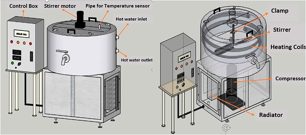
FIGURE 1. Design of the solar assisted yogurt processing unit in CAD software.
For heating of raw milk, the yogurt processing unit was connected with a hot water storage tank (100 L capacity) which received heat from a solar evacuated tube collector (2.5 m2) having a connection through polyvinyl chloride (PVC) pipe fittings, as shown in Figure 2.
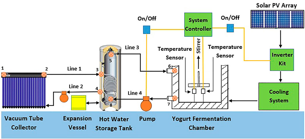
FIGURE 2. Layout of the experimental setup of the solar assisted yogurt processing unit.
The outer and inner diameters of ETC tubes were Ø58 mm ± 0.7 mm and Ø47 mm ± 0.7 mm, respectively. The glass tube length was 1800 ± 5 mm, and the vacuum was P < 5 × 10−³ Pa. The thermal energy absorbed by the collector was transferred to 100 L of water in the storage tank to raise the water temperature to 90°C. A centrifugal pump (Wilo-SP106) was installed between the hot water storage tank and evacuated tube collector for the circulation of propylene glycol solution (50% by volume). The pump could be operated at three variable speeds (600 L/h, 900 L/h, and 1100 L/h), and it required 80 W power at maximum speed. The current research was conducted at a flow rate of 600 L/h. Heated glycol solution entered the storage tank and transferred its heat to water while passing through the helix-type heat exchanger present in the storage tank. In order to transfer heat from the storage tank to the yogurt processing unit, another water circulation pump (stainless steel centrifugal, WB50/025D, 50 L/min) was installed between the outlet of the hot water storage tank and the inlet of the yogurt processing unit to circulate the hot water through the square spiral coil heat exchanger to raise the temperature of milk up to 80°C.
Being a closed cycle, an expansion vessel (12 L) was also provided to avoid the high pressure build up in the system. The controller turns on the circulation pump (Wilo-SP106) when the temperature differential between the glycol solution leaving the collector and the water in the lower portion of the storage tank exceeds 5°C and turns it off when the differential is below 5°C or when the water temperature of the storage tank exceeds 90°C. An electric heating coil (2 kW) is also mounted inside the hot water storage tank to process the milk/yogurt in the low or no sunshine hours.
2.2 Details of Experiments Performed
Trials were conducted to assess the heating and cooling performances using three different volumes of raw milk (30, 40, and 50 L). Before conducting an experiment, the heating component of the system was turned on to raise the water temperature of the storage tank up to 90°C, which normally took 2–3 h depending on solar radiation. After that, raw milk was poured into the fermentation tank, and the circulation of hot water from the storage tank to the fermentation chamber was turned on. The heating of raw milk up to 80°C took about 140 min, and it was continuously stirred at the speed of 36 rpm. In order to bring down the temperature of heated milk to 43°C, recommended for fermentation of milk, tap water was passed through the heating coil in an open loop controlled by manually operating valves. Inoculation of starter culture was performed (2-3%) at this temperature and was maintained through a solenoid valve which controlled the circulation of water for a period of 5–6 h until the required pH (4.85–4.5) was attained. After that process, the cooling process of yogurt was started by turning on the refrigeration unit to bring down the temperature of yogurt below 8°C to reduce the bacterial activities, which normally took 48–103 min depending on the quantity of the processed milk and stirrer speed. For this, three different speeds (36, 18, and 6 rpm) of stirring were selected using a variable speed motor. Experiments were conducted with three milk volumes (50, 40, and 30 L). Each experiment was conducted three times, and values were averaged. For data acquisition, a controller with resistance temperature detector (RTD)-based temperature sensors (accuracy ± 0.1°C) was used to measure temperature at the inlet and outlet of ETC, top and bottom of the hot water storage tank, and inside the fermentation chamber. A portable pH meter (ML1010) was used to measure the pH of milk during the fermentation process. To assess the performance of the installed PV system, a clamp meter (Fluke 345PQ) and pyranometer (METEON) were used.
3 Thermodynamic Analysis
Due to the exchange of heat at various positions of the yogurt processing unit, the condition of working fluid (50% water–glycol solution and water) changes as it flows through the system at different positions marked in Figure 2.
3.1 Thermal Efficiency of the Solar Collector (Evacuated Tube Collector)
There are different options to couple various types of solar collectors for heating milk, like flat plate collectors and solar concentrators, but the evacuated tube collector (ETC) was chosen because of its high efficiency, compactness, and durability and it does not need any tracking system. The glass vacuum tube material was borosilicate glass, and the structure was a concentric dual-tube geometer. The average heat loss coefficient from tubes was 0.8 W/m2K. For the storage of hot water, a stainless steel tank with 100 L storage capacity was installed. The temperature from ETC can be achieved up to 100°C plus. The input power at ETC is calculated by the following equation (Munir et al., 2021):
where G′ is the rate of incident solar energy at the collector (kW), It is total solar irradiance or GHI (global horizontal irradiation) (W/m2), and Ac is collector surface area (m2) and is calculated by multiplying effective tube length (exposed to solar radiation) by its diameter (aperture) and the number of tubes.
The thermal efficiency of the solar evacuated tube collector depends on solar input energy and losses and heat transferred to the working fluid (water + glycol solution), and its value lies in the range of 70–80%. So, the amount of heat energy transferred can be estimated by multiplying the mass flow rate with the specific heat of the fluid and the change in temperature (Munir et al., 2021):
where Q′ stands for the energy-transferred rate (collector to water–glycol solution) in kW, Cp is specific heat capacity (kJ/kg K), m` stands for flow rate (kg/s), and T2 and T1 are the temperatures at respective points shown in Figure 2:
3.2 Energy Analysis of the Yogurt Processing Unit
In order to transfer heat from the storage tank to the yogurt processing unit, a water circulation pump was installed between the outlet of the hot water storage tank (point 5) and the inlet of the yogurt processing unit (point 6) to circulate the hot water through the square spiral coil heat exchanger to raise the temperature of milk up to 80°C, and its conditions continued to change during the heating process.
3.2.1 Heating Process
3.2.1.1 Conditions of Working Fluid (Glycol and Water Solution) Across the Heating Unit
The working fluid is circulated between the evacuated tube collector and the storage tank. It enters into the collector at point 1 (Figure 2) and after getting heat, exits at point 2. As line 1 is insulated, so the heat losses from point 2 to point 3 are supposed to be negligible. Therefore, thermal conditions of working fluids are considered the same both at the outlet of the solar collector (point 2) and the inlet of the storage tank (point 3). The heat of incoming fluid is absorbed by the water stored in the tank and leaves at point 4 and re-enters into the collector. The described conditions of the working fluid can be written as follows:
where T is the temperature (K), h is enthalpy (kJ/kg), and the subscripts ci and co stand for solar collector inlet and outlet, respectively, while subscripts si and so stand for storage tank inlet and outlet, respectively.
The rate of energy transferred to the storage tank water (Q′3–4) can be calculated using the following equation:
where T3 and T4 are the temperatures at respective points shown in Figure 2.
3.2.1.2 Conditions of Working Fluid (Water) Across the Processing Unit
In order to heat the product, water is circulated between the processing unit and the storage tank. The hot water coming out of the storage tank at point 5 enters into the square helix coil of the processing unit (point 6), considering negligible thermal losses in line 3. So, thermal conditions of the working fluid are considered the same both at the outlet of the storage tank (point 5) and the inlet of the processing unit (point 6). The heat of incoming hot water is absorbed by the product (milk/yogurt) and leaves at point 7 and re-enters into the storage tank at point 8 (Figure 2). The described conditions of the working fluid can be written as:
where subscripts pi and po stand for the yogurt processor inlet and outlet, respectively.
The rate of energy transferred to the milk (Q′6–7) can be calculated using the following equation:
where T6 and T7 are the temperatures at respective points shown in Figure 2.
3.2.2 Cooling Process
The cooling process involves the cooling of pasteurized milk, followed by maintaining its temperature for the fermentation process and finally cooling of yogurt. The amount of heat extracted from the product can be calculated using the following equation (Khan et al., 2020):
where Q′ is the amount of heat energy extracted (kW), TPi stands for product temperature at the start of cooling, and TPf stands for product temperature after a specific interval of time.
Energy input to the refrigeration unit from the off-grid PV system can be calculated as (Gonen T, 2012):
where V is volt, I is current, and cosθ is the phase angle between voltage and current and is also referred to as power factor (PF).
Moreover, using Equations 6, 7, the coefficient of performance (COP) of the installed refrigeration system (one ton) was also calculated.
3.3 Exergy Analysis
In addition to energy analysis, exergy analysis has been used widely in recent years (Aghbashlo et al., 2013). Fundamental principles of energy and mass conservation are used for the assessment of energy flow in and flow out of the system. For this, the following equations are used to calculate exergy flows (inflow, outflow, and loss) (Amjad et al., 2020):
where T is the temperature of the respective points, Ta is the ambient temperature, and the subscript i is for initial.
For the thermal analysis, the entire system was divided into heating and cooling processes.
3.3.1 Heating Process
Using the measured temperature of working fluid (water) at the inlet and outlet of the processing unit, the values of exergy inflow and outflow of the processing unit can be calculated. The hot water from the storage tank enters into the processing unit (point 6 in Figure 2) and leaves at point 7 (Figure 2). Using Equation 8 with respective temperature values, exergy inflow and outflow can be calculated as follows:
where subscript pui stands for processing unit inlet.
Similarly, using the temperature value of outlet water, exergy outflow can be calculated as:
where subscript puo stands for processing unit outlet.
The difference between exergy inflow and outflow gives exergy loss (energy destructed/used in the yogurt fermentation chamber during the heating process of milk).
3.3.2 Cooling Process
For the exergy analysis of the cooling part, the following equations are used to calculate exergy loss and exergy efficiency. As the integrated vapor compression refrigeration unit is powered by solar energy (photovoltaic), exergy received by the solar PV panels needs to be calculated. The incident radiation energy on the PV panels is given by the following equation (Baghernejad et al., 2016; Abuelnuor et al., 2017):
where Ap is the exposed area of the PV panel to sunlight and It is the total solar irradiance.
It should be noted that the exergy of the electrical power was assumed to be equal to its energy. The exergy received by the PV panel is given by the following equation (Mathkor et al., 2015):
The exergy recovered during refrigeration is given as follows (Mathkor et al., 2015):
where COPmax is the maximum possible coefficient of performance, COP is the actual coefficient of performance of the compressor (based on product temperature), and Ecomp is the energy supplied to the compressor of the cooling system. In this analysis, the electrical exergy was assumed to be equal to its energy because the entire amount of electrical energy has the potential to do useful work. As a result, the exergy efficiency of the system is given by the following equation (Mathkor et al., 2015):
Cooling is absorbed by the milk inside the chamber directly contacted with the pillow plate. The change in milk temperature was recorded at an interval of 5 minutes throughout the process.
3.4 Calculation of Thermal Losses
The ETC header, hot water storage tank, PVC pipes for connection, and yogurt processing chamber are of cylindrical shape. The required physical and thermal parameters, as tabulated in Table 1, are used to calculate the lateral conduction, convection, and radiation losses from their walls with insulation and without insulation.
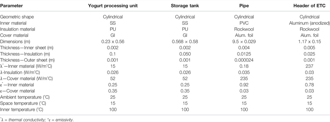
TABLE 1. Metadata for the current prototype of the solar assisted yogurt processing unit.
For entire calculations, ambient, space temperatures, and solar insolation were supposed to be 25°C, 15°C, and 800 W/m2, respectively. For a cylindrical layer that is exposed to a convective heat transfer mechanism on both sides, the steady-state heat transfer (φ) can be calculated as (Cengel, 2004; Munir et al., 2021):
where Tin stands for the inside temperature of the processing chamber, Tamb represents ambient temperature, Rcond symbolizes the resistance due to conduction, and Rconv denotes convection resistance.
Thermal conduction resistance for the lateral cylindrical wall is calculated as (Cengel, 2004; Munir et al., 2021):
where “rint” and “rext” are the inner and outer radius of the cylindrical shape of the hot water storage tank, yogurt fermentation chamber, header of ETC and PVC pipes. λ is the material thermal conductivity (stainless steel sheet 15 Wm−1K−1), and L stands for the lateral length of the cylindrical body, and the area of the outer sheet and inner sheets would be equal when rint is equal to rext (in case of no insulation).
The conductive resistance for multilayered plane wall with insulation is calculated by adding the conductive resistance for all layers and is given in Eq. 17:
where subscripts “os,” “ins,” and “is” represent the outer sheet, insulation, and inner sheet, respectively. The values of conductivity resistance for outer sheet, insulation, and inner sheets are calculated for the hot water storage tank, yogurt processing unit, the header of ETC, and insulated PVC pipes and tabulated in Table 2.
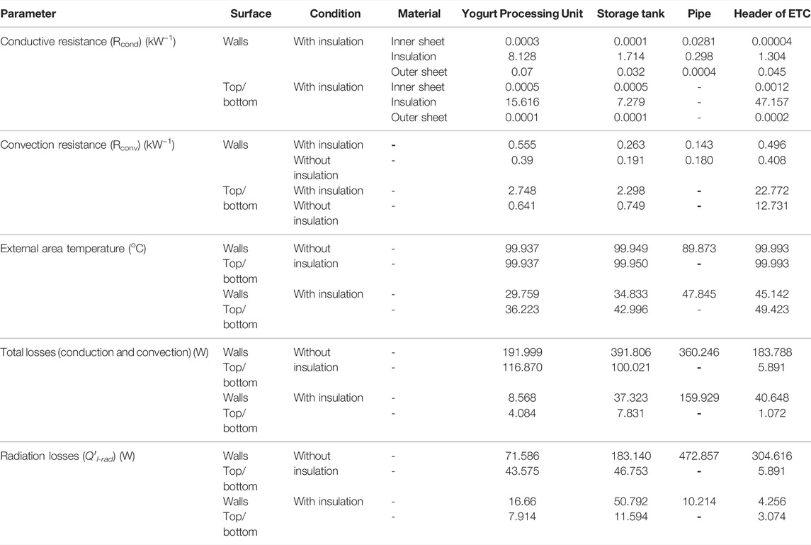
TABLE 2. Parameters calculated for the thermal analysis of the current prototype of the solar assisted yogurt processing unit.
The values of conduction resistance for the circular part (top and bottom) of the hot water tank, yogurt processing unit, and header of ETC are calculated by the following relation (Cengel, 2004; Munir et al., 2021):
With insulation, the conductive resistance for the multilayered plane wall is calculated by adding the conductive resistance for all layers and is given in Eq. 19:
where “t” is the wall thickness, “r” is the radius of circular section, and subscripts “os,” “ins,” and “is” represent the outer sheet, insulation, and the inner sheet, respectively. The values of conductivity resistance for outer sheet, insulation, and inner sheets are calculated and tabulated in Table 2. Convection resistance is calculated by the following relation (Munir et al., 2021):
where ‘h’ stands for the natural convectional coefficient, and its value is assumed. ‘A’ is the area of the sheet. In order to calculate the resistance due to convention, an iterative technique was used by taking values of the physical parameters like air density (ρa=1.050), dynamical viscosity (μ)-air (μa = 0.000020500), conductivity-air (ʎa = 0.0295), air-specific heat capacity (aa = 1,009), static viscosity-air (Va = μa/ρa = 0.0000195,238), and Prandtl (Pr)-air (Pr=Ca* μa/ʎa = 0.7011).
The Grashof number is calculated as (Munir et al., 2021):
where “β” stands for the coefficient of thermal expansion, g stands for gravitational acceleration (9.81 ms−2), and “L” is the height of the cylindrical vessel.
For the calculations of the Nusselt number (Nu), if the output of the product Prandtl number (Pr) and Grashof number (Gr) lies between 104 and 109, Eq. 22 will be used, and in case it lies between 109 and 1013, then Eq. 23 will be used (Munir et al., 2021):
The convective heat coefficient is calculated as (Munir et al., 2021):
Using the iterative method, the final value of ‘h’ was calculated until the assumed and the calculated values became equal. The values of convection resistance for walls and top/bottom are calculated with insulation and without insulation for hot water storage tank, yogurt processing unit, the header of ETC, and walls of PVC pipes and tabulated in Table 2.
Radiation losses (Q′l-rad) are calculated by the following relation (Munir et al., 2021):
where ε is the emissivity, δ is the Stephen–Boltzmann constant, Tspace is the space temperature (K), and Text is the external area temperature (K).
The external area temperatures are calculated by the following equation (Munir et al., 2021):
The values of external area temperatures and radiation losses for walls and top/bottom are calculated with insulation and without insulation for hot water storage tank, yogurt processing unit, the header of ETC, and walls of PVC pipes and tabulated in Table 2.
4 Results and Discussion
4.1 Energy Analysis
For the energy analysis, the amount of heat energy transferred and absorbed was calculated. Figure 3 shows the cumulative heat energy released by hot circulating water, heat energy absorbed by milk, and correspondence heat transfer efficiency.

FIGURE 3. Total heat energy released by water and absorbed by milk during the processing of 50 L (A), 40 L (B), and 30 L (C) milk.
It was found that during the first 40 min of the heating process, hot water released 66, 69, and 74% of its total energy for 50, 40, and 30 L of milk capacities, as shown in Figures 3A,B,C, respectively. The rest of the energy was transferred to milk in the next 100, 70, and 40 min for 50, 40, and 30 L of milk. On the contrary, the milk absorbed 69, 81, and 84% of the total required energy to reach the desired temperature of 80°C. Therefore, the quantity of milk plays an important role in energy consumption. As soon as raw milk was poured into the processing chamber, the rate of energy utilization increased due to the removal of a high quantity of heat. The heat transfer efficiency was found to be above 80% during the whole heating process because milk received energy from the storage tank in which any fluctuation was compensated continuously by ETC. It can be observed that the maximum amount of incoming heat energy absorbed by milk in case of 50 L comparative to the other two qualities, that is, 30 and 40 L, as evident by less gap between the curves of cumulative heat energy absorbed and released. The reason is that the system has been designed for 50 L capacity, and in the case of fully loaded, the heating coil is fully exposed to the milk. Moreover, as soon as the milk temperature reached 70°C, the amount of heat energy absorbed reduced leading to lower heat transfer efficiency. Energy utilization during a hearing process is mainly associated with the temperature difference between circulating hot water and milk as well as milk quality.
The energy used for the heating process followed by fermentation and cooling processes is provided by solar thermal and solar photovoltaic systems. The overall energy consumption for yogurt made from raw milk was calculated to be 6.73 kWh, 5.56 kWh, and 4.21 kWh for 50, 40, and 30 L batches, respectively. Out of this, 40% of energy was consumed during the heating process of 50 L, which was 39% for the cases of 40 and 30 L, while 27% was used for the cooling process of milk (with tap water) for 50 L and 29% for the cases of 40 and 30 L. This shows that the heating process consumed more energy followed by the cooling process in all the cases. During the cooling process of yogurt, 31% of the total energy was consumed for 50 L and 30% for the cases of 40 and 30 L, and the rest of the energy (2%) was used for the fermentation process in all cases. Therefore, the specific production energy (SPE) was calculated to be 485 kJ/kg, 500 kJ/kg, and 505 kJ/kg for 50, 40, and 30 L batches, respectively.
4.2 Exergy Analysis
4.2.1 Exergy Analysis of the Heating Process
The yogurt processing chamber is the main part of the system in which significant heat transfer takes place both in cases of heating and cooling processes. Heat transfer occurs between the working medium (hot water for heating and refrigerant for cooling) and the product (milk and yogurt). Figure 4A shows the change in exergy loss during the heating process of raw milk under different batch capacities. It can be observed that exergy destruction was high at the start of the heating process due to the large temperature difference and reduced with the rise of milk temperature. It could be explained in a similar way as earlier in the case of the rate of energy utilization. It can also be noted, especially at early stages that less amount of exergy losses occurred in case of low batch capacity (30 L), which is not economical to process in terms of energy utilization leading to the untapped energy potential of circulating water. It shows that the system should be used at least for 40 L capacity as it has been designed for a maximum of 50 L. During the entire heating process, the exergy losses varied in ranges of 0.23–4.49 kJ/kg, 0.17–3.95 kJ/kg, and 0.06–0.9 kJ/kg for 50, 40, and 30 L batches, respectively. This shows that the system is capable of providing maximum heating for the processing of the designed product capacity (i.e., 50 L). On the other side, the exergetic efficiencies of the heating process under different milk volumes have been shown in Figure 4B.
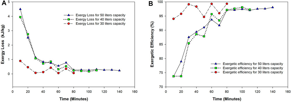
FIGURE 4. Exergy losses (A) and exergy efficiencies (B) during heating processing of 50, 40, and 30 L raw milk.
Exergy efficiency depends on the rate of exergy loss which ultimately depends on the amount of exergy inflow and outflow. The relationship between exergy loss and exergy efficiency is inversely proportional, that is, the higher the exergy destruction, the less would be the exergetic efficiency. Therefore, it can be observed that earlier during the heating process, exergy efficiencies were lower because of higher exergy losses in all cases of milk volume, followed by an increase in efficiencies later on. The values of exergy efficiency during the entire heating process were in ranges of 78–98%, 78–97%, and 94–99% for 50, 40, and 30 L, respectively, along with average values of 91.98% (50 L), 79.88% (40 L), and 97.07% (30 L).
4.2.2 Exergy Analysis of the Cooling Process
The temperature of the fermented yogurt was reduced from 43 to 4°C using a pillow plate coupled with one ton of the refrigeration system. The exergy inflow into the pillow plate was constant, based on the design of one ton of the refrigeration unit. The amount of exergy inflow received from the solar photovoltaic (PV) system is used to run the compressor to impart refrigeration effect and exergy used during the refrigeration process. The exergy received by the PV panel (Exi) was calculated to be in the range of 9.48–10.29 kW (56.87–61.75 kJ/kg) during the cooling process of 50 L of yogurt. The exergy losses in the compressor of the refrigeration unit were calculated almost constant (1.0037 kW) as shown in Figure 5A. It can be noted that during the yogurt cooling process, the amount of energy transferred from the pillow plate was high, especially at the early stages, which lowered down once the product reached 4°C. So, the exergy destruction is on the higher side during the cooling process because of the temperature difference between the product and the pillow plate. Second, the bottom side of the pillow plate is fully insulated with polyurethane (PU) foam resulting in negligible cooling losses. The exergy recovered during the refrigeration (Exref) process was found in the range of 0.76–0.08 kW (4.54–0.48 kJ/kg) with a total exergy loss of 1.76–1.08 kW (10.38–6.67 kJ/kg) during the entire cooling time (73 min) of 50 L product.
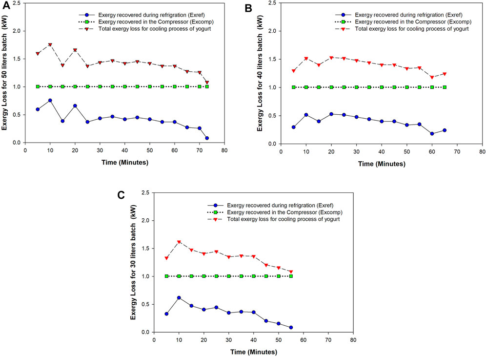
FIGURE 5. Exergy losses in refrigeration unit and cooling of yogurt for 50 L (A), 40 L (B), and 30 L (C) batch capacities.
Similarly, in the case of other product quantities, the rate of exergy destruction to run the compressor was the same, while exergy used during the cooling process varied depending upon the product quantity, as shown in Figures 5B,C for 40 and 30 L, respectively. As the cooling proceeded to achieve the desired temperature (4°C), the exergy losses were reduced based on the quantity to be processed, that is, 30 L batch cooled down earlier than 40 and 50 L. The more the quantity to be cooled, the higher would be the exergy loss so economical to run the system at full capacity in terms of energy utilization. The exergy recovered during refrigeration (Exref) processes was calculated in the range of 0.53–0.18 kW (3.96–1.35 kJ/kg) and 0.62–0.084 kW (6.18–0.84 kJ/kg) for 40 and 30 L of batches, respectively.
The average values of total exergy extracted were found to be 1.42, 1.39, and 1.35 kW for 50, 40, and 30 L batch capacities, respectively, which indicated that for 40 and 30 L volumes, the exergy recovered/extracted during the cooling process was found to be 2.11 and 4.92% less than that in 50 L batch, respectively. Contrarily, the exergy efficiency during the cooling process was found low for all the batches due to maximum cooling energy transfer, as shown in Figure 6. The values of exergetic efficiency were found in the range of 18.14–10.70%, 15.35–11.64%, and 16.79–11.72% for 50, 40, and 30 L, respectively.
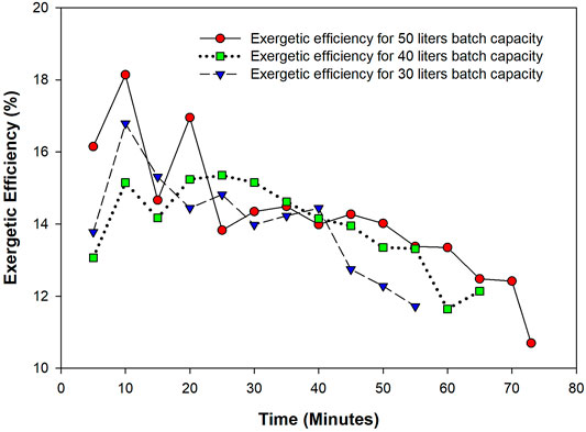
FIGURE 6. Exergy efficiency during the cooling process of yogurt for 50, 40, and 30 L batch capacities.
Moreover, fluctuations at the early stages of the cooling process can be observed. In the case of 50 L, two major fluctuations occurred in the values of exergy loss and exergetic efficiency at 15 and 25 min of cooling process time. The exergetic efficiency varied from 18.14–14.66% and 16.95–13.82% at these time intervals and after that curve moved slightly on lower exergetic efficiency. Similarly, in the case of 40 and 30 L, a sudden decline in the values of exergetic efficiency can be observed at 15 min of time interval where efficiency dropped from 15.15–14.17% and 16.79–14.44%, respectively. This could be due to the presence of static hot water (83°C) in the heating coils surrounded by the fermentation chamber at the starting time of the cooling process of yogurt. As discussed earlier, a pillow plate is used at the bottom of the fermentation chamber, so the cooling effect produced by the refrigerant is directly transferred to yogurt. The cooling effect produced in yogurt is then transferred to the hot water in the coil and walls of the chamber for thermodynamic equilibrium; in other words, the heat energy from hot water in the coils is transferred to the yogurt due to high-temperature difference. As a result, net exergy recovered during refrigeration (Exref) is decreased from 0.76–0.39 kW to 0.66–0.37 kW for 50 L batch capacity and from 0.52 to 0.4 kW and 0.62 to 0.41 kW for 40 and 30 L batch capacities for their respective time intervals, respectively, resulting in decreased in exergetic efficiency.
4.3 Power Distribution
In this study, an evacuated tube collector (ETC) was used for heating applications during the yogurt-making process. A complete algorithm was prepared by taking into consideration useful solar energy available and losses at various sections. The average solar insolation value was taken as 800 Wm−2 during the experiment. The main important feature of this heating system is the addition of hot water storage which always runs to store hot water in this insulted closed chamber for the effective hot water supply to the yogurt processing unit, but this storage of additional energy has not been taken into consideration. The calculation is based on the step-by-step calculation of available energy and losses at ETC, pipelines, hot water tank, and yogurt processing unit, as shown in Figure 7. In this study, 15 tubes were used, and the total power available on ETC was calculated to be 2218 W. Out of this energy, 5% was the transmission losses, and 5% was the absorbance losses, with a total of 10% of optical losses from ETC. The optical losses were calculated to be 197 W. Water in the tubes was heated due to the thermo-siphon system, and heated water was stored in the insulated top header. The thermal losses inside the header were calculated to be 53 W. So, 1968 W power was available from ETC. The power transferred to the hot water storage tank was 1718 W which was insulated by 50-mm-thick polyurethane. The hot water storage tank stores the thermal energy coming from ETC. The important feature of this hot water storage tank is that it also stores the energy when the yogurt is not processed and always keeps the tank in the thermal potential to be used for processing applications. An electrical coil is also fitted inside the hot water storage tank to heat water in case of cloudy weather conditions. The thermal losses from the hot water tank were calculated to be 127 and 1591 W available for the yogurt processing unit. The line losses in the form of conduction, convection, and radiation in the PVC pipes were found to be 170 W; therefore, the net energy available for the yogurt processing unit was calculated to be 1421 W. Out of this available power for the processing unit, 49 W is thermal losses; therefore, 1372 W is available for useful work. If we calculate the energy required for milk processing/heating, 1350 W power is required to process 50 L of milk/yogurt in 2 h for a temperature differential of 50°C having a specific heat of 3.89 kJ/kg/K. So, the thermal energy available to heat the milk is 1372 W which is greater than the actual power demand, thus justifying the number of tubes and the size of ETC. We may assume this additional energy as undetermined losses, and this power is utilized for thermal storage in the hot water tank. The complete distribution is shown in Figures 7A,B.
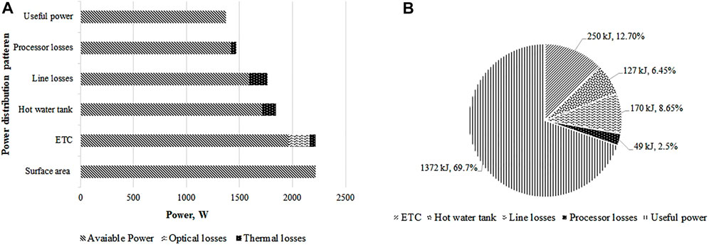
FIGURE 7. Distribution of various losses and useful energy in terms of power (A) and percentage (B).
Table 3 summarizes some of the related studies regarding thermal analysis of yogurt/milk processing for a comparative assessment of the current solar yogurt processing unit. Although the quantity of the product to be processed, design of the process, and operating conditions vary and are important for the rates of energy usage, it can be observed that the solar yogurt processing unit gave quite good results. The exergetic efficiency of the current unit is higher than all the tabulated other studies. Even dealing higher quality of product, the specific exergy consumption is less than that of the processing plant reported by Mojarab et al. (2016) while almost similar to that reported by Mojarab & Aghbashlo (2017). Compared with the industrial-scale yogurt processing plant, the overall exergy efficiency and specific exergy consumption are less. Although the difference between the values of specific exergy consumption is almost 50% in comparison to the large difference of quantity being dealt into both cases; however, it is understandable that processing large quantities leads to decreased specific energy consumption. Abu-hamdeh (2020) conducted an exergetic analysis on the combined cooling, heating, and power (CCHP) system based on a PVT collector. It can be observed that the specific energy consumption rate of hot water was 3.78 kW for 350 L of water capacity, while in the current study the specific energy consumption rate of milk was 2.89 kW for 50 L batch capacity. Exergy extracted by hot water was 0.2343 kW which lies in the range of the current study (0.019–0.374 kW for 50 L), and exergy extracted during refrigeration was 0.09122 kW which is lower than that reported in the current study (1.76–1.08 kW for 50 L). It was because of the use of a vapor compression refrigeration system (COP 4.33) in the current study, while a vapor absorption refrigeration system (lower COP of 0.615) was used by Abu-hamdeh (2020).
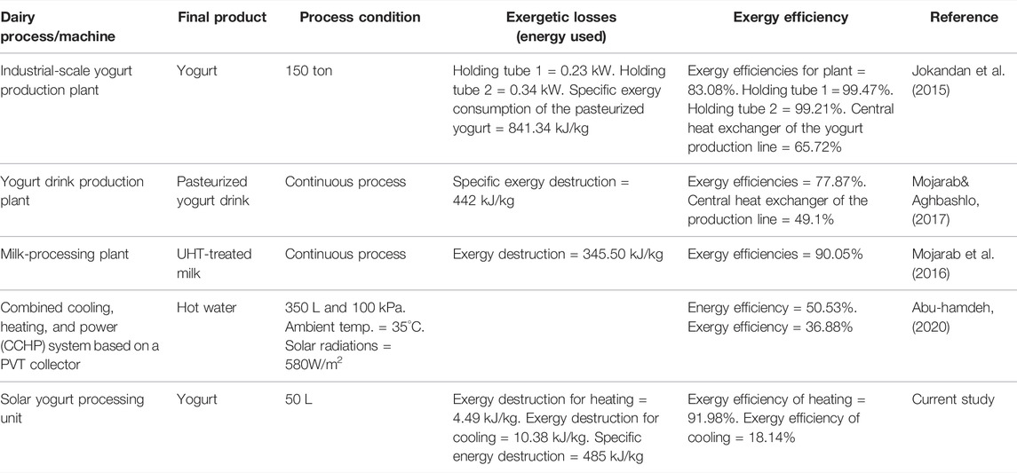
TABLE 3. Comparison of thermal analysis conducted for the performance evaluation of different dairy product processes and machines.
5 Conclusion
In this study, a detailed thermal analysis of a solar assisted yogurt processing unit has been carried out. The study shows that system was able to process the raw milk for yogurt using solar energy. The following conclusions are made:
a) During the milk-heating process, the heat transfer efficiency was found to be above 80%, with a maximum amount of incoming heat energy absorbed by 50 L of milk due to more exposure of the product to the heating coil for maximum use of the heating potential of the coil.
b) Out of the total energy consumption for the entire yogurt-making process from the raw milk, almost 40% was used during the heating process of raw milk showing that the heating process consumed more energy than the cooling process in all the cases.
c) The amount of energy consumed to produce 1 kg of the product was calculated to be 485 kJ/kg, 500 kJ/kg, and 505 kJ/kg for 50, 40, and 30 L batches, respectively, showing that the system should be run at full capacity.
d) Exergy analysis of the heating process revealed that exergy losses varied in ranges of 0.23–4.49 kJ/kg, 0.17–3.95 kJ/kg, and 0.06–0.9 kJ/kg for 50, 40, and 30 L batches, respectively. Exergy analysis of the cooling process showed a total exergy loss of 1.76–1.08 kW (10.38–6.67 kJ/kg) during the entire cooling time (73 min) of 50 L product.
e) It was found that thermal energy available to heat the milk is 1371 W, while 1350 W power is required to process 50 L of yogurt for a temperature differential of 50°C. So, the thermal energy available to heat the milk is greater than the actual power demand, thus justifying the number of tubes and the size of ETC.
f) For thermal analysis, step-by-step calculation of available energy and losses with respect to geometry and thermal properties provides the baseline for the design optimization of the system to handle the large quantities of the product. It can be used to scale up the design.
g) Being affordable and clean energy, integrating solar energy (both solar thermal and solar PV) with dairy-processing units provides a good opportunity and efficiency to perform dairy processes at the farm level (decentralized applications).
Data Availability Statement
The raw data supporting the conclusion of this article will be made available by the authors, without undue reservation.
Author Contributions
SH, WA, AM, and OH contributed to the conception and design of the study. SH and AM performed the thermal losses analysis. SH and WA wrote the first draft of the manuscript. OH and AM wrote sections of the manuscript. All authors contributed to manuscript revision, and read and approved the submitted version.
Funding
The development cost of the system was provided by the International Center for Development and Decent Work (ICDD) Germany.
Conflict of Interest
The authors declare that the research was conducted in the absence of any commercial or financial relationships that could be construed as a potential conflict of interest.
Publisher’s Note
All claims expressed in this article are solely those of the authors and do not necessarily represent those of their affiliated organizations, or those of the publisher, the editors, and the reviewers. Any product that may be evaluated in this article, or claim that may be made by its manufacturer, is not guaranteed or endorsed by the publisher.
Acknowledgments
The author thanks the Higher Education Commission (HEC) of Pakistan and the German Academic Exchange Service (DAAD) for providing subsistence/research costs for the current study. The Author would also like to thank the University of Kassel, Germany for providing funds for publishing the work.
References
Abu-hamdeh, N. H. (2020). Energy and Exergy Analysis and Optimum Working Conditions of a Renewable Energy System Using a Transient Systems Simulation Program. Energy Explor. Exploitation. 38 (4), 1248–1261. doi:10.1177/0144598720908071
Abuelnuor, A. A. A., Saqr, K. M., and Mohieldein, S. A. A. (2017). Exergy Analysis of Garri “2” 180 MW Combined Cycle Power Plant. Renew. Sustain. Energy Rev. 79, 960–969. doi:10.1016/j.rser.2017.05.077
Aghbashlo, M., Mobli, H., Rafiee, S., and Madadlou, A. (2013). A Review on Exergy Analysis of Drying Processes and Systems. Renew. Sustain. Energy Rev. 22, 1–22. doi:10.1016/j.rser.2013.01.015
Amjad, W., Ali Gilani, G., Munir, A., Asghar, F., Ali, A., and Waseem, M. (2020). Energetic and Exergetic Thermal Analysis of an Inline-Airflow Solar Hybrid Dryer. Appl. Therm. Eng. 166, 114632. doi:10.1016/j.applthermaleng.2019.114632
Atia, F. M., M Mostafa, M., A El-Nono, M., and F Abdel-Salam, M. (2011). Solar Energy Utilization for Milk Pasteurization. Misr J. Agric. Eng. 28, 729–744.
Baghernejad, A., Yaghoubi, M., and Jafarpur, K. (2016). Exergoeconomic Optimization and Environmental Analysis of a Novel Solar-Trigeneration System for Heating, Cooling and Power Production Purpose. Sol. Energy 134, 165–179. doi:10.1016/j.solener.2016.04.046
Brush, A., Eric, M., and Ernst, W. (2011). Energy Efficiency Improvement and Cost Saving Opportunities, an ENERGY STAR ® Guide for Energy and Plant Managers. Berkeley, CA 94720: Energy Analysis Department Environmental Energy Technologies Division Lawrence Berkeley National Laboratory.
Bühler, F., Nguyen, T.-V., Jensen, J. K., Holm, F. M., and Elmegaard, B. (2018). Energy, Exergy and Advanced Exergy Analysis of a Milk Processing Factory. Energy 162, 576–592. doi:10.1016/j.energy.2018.08.029
Bylund, G. (2003). Dairy Processing Handbook, S-221 86 Lund, Sweden. Tetra Pak Processing Systems AB.
Desai, D. D., Raol, J. B., Patel, S., and Chauhan, I. (2013). Application of Solar Energy for Sustainable Dairy Development. Ejsd 2 (2), 131–140. doi:10.14207/ejsd.2013.v2n2p131
Dobrowsky, P. H., Carstens, M., De Villiers, J., Cloete, T. E., and Khan, W. (2015). Efficiency of a Closed-Coupled Solar Pasteurization System in Treating Roof Harvested Rainwater. Sci. Total Environ. 536, 206–214. doi:10.1016/j.scitotenv.2015.06.126
Eddhibi, F., Amara, M. B., Balghouthi, M., Qoaider, L., and Guizani, A. A. (2017). Analytic Optical Design of a Linear Fresnel Solar Collector with Variable Parameters. J. Mater. Environ. Sci. 8 (11), 4068–4084.
Gonen, T. (2012). Electrical Machines with Matlab. Second Edition. Taylor & Francis Group, LLC. 9781439878002.
Husnain, S. N., Amjad, W., Munir, A., and Hensel, O. (2022). Development and Experimental Study of Smart Solar Assisted Yogurt Processing Unit for Decentralized Dairy Value Chain. Sustainability 14, 4285. doi:10.3390/su14074285
Ismail, M. I., Yunus, N. A., and Hashim, H. (2021). Integration of Solar Heating Systems for Low-Temperature Heat Demand in Food Processing Industry - A Review. Renew. Sustain. Energy Rev. 147 (April), 111192. doi:10.1016/j.rser.2021.111192
Jafaryani Jokandan, M., Aghbashlo, M., and Mohtasebi, S. S. (2015). Comprehensive Exergy Analysis of an Industrial-Scale Yogurt Production Plant. Energy 93, 1832–1851. doi:10.1016/j.energy.2015.10.003
Khan, K. S., Amjad, W., Munir, A., and Hensel, O. (2020). Improved Solar Milk Chilling System Using Variable Refrigerant Flow Technology (VRF). Sol. Energy 197, 317–325. doi:10.1016/j.solener.2020.01.014
Mathkor, R., Agnew, B., and Al-Weshahi, M. (2015). Exergetic Analysis of an Integrated Tri-generation Organic Rankine Cycle. Energies 8, 8835–8856. doi:10.3390/en8088835
Mekhilef, S., Saidur, R., and Safari, A. (2011). A Review on Solar Energy Use in Industries. Renew. Sustain. Energy Rev. 15, 1777–1790. doi:10.1016/j.rser.2010.12.018
Michael, M. B., Akinlabi, E. T., and Jen, T. C. (2016). A Review of Solar Thermal Systems Utilization for Industrial Process Heat Applications. Lect. Notes Eng. Comput. Sci. 2226, 859–863.
Mojarab, S. M., and Aghbashlo, M. (2017). Application of Exergy Analysis to the Dairy Industry_ a Case Study of Yogurt Drink Production Plant. J. Food Bioprod. Process. 101, 118–131. doi:10.1016/j.fbp.2016.10.008
Mojarab, S. M., Aghbashlo, M., and Mobli, H. (2016). Exergetic Performance Assessment of a Long-Life Milk Processing Plant: a Comprehensive Survey. J. Clean. Prod. 140, 590–607. doi:10.1016/j.jclepro.2015.11.066
Munir A, A., Hensel, O., Scheffler, W., Hoedt, H., Amjad, W., and Ghafoor, A. (2014). Design, Development and Experimental Results of a Solar Distillery for the Essential Oils Extraction from Medicinal and Aromatic Plants. Sol. Energy 108, 548–559. doi:10.1016/j.solener.2014.07.028
Munir, A., Mahmood, F., Amjad, W., and Ahmad, S. A. (2021). Thermal Analysis of a Solar Hybrid Dehydrator Designed for Uniform Multi-Product Drying. J. Therm. Sci. Eng. Appl. 13 (6). doi:10.1115/1.4050232
Munir M T, M. T., Yu, W., and Young, B. R. (2014). Can Exergy Be a Useful Tool for the Dairy Industry? Comput. Aided Chem. Eng., 1129–1134. doi:10.1016/B978-0-444-63455-9.50023-4
Singh, G., Chopra, K., Tyagi, V. V., Pandey, A. K., Ma, Z., and Ren, H. (2021a). A Comprehensive Energy, Exergy and Enviroeconomic (3-E) Analysis with Carbon Mitigation for Multistage Evaporation Assisted Milk Powder Production Unit. Sustain. Energy Technol. Assessments 43 (November 2020), 100925. doi:10.1016/j.seta.2020.100925
Singh, G., Tyagi, V. V., Chopra, K., Pandey, A. K., Sharma, R. K., and Sari, A. (2021b). Energetic and Exergetic Assessment of Two- and Three-Stage Spray Drying Units for Milk Processing Industry. J. Braz. Soc. Mech. Sci. Eng. 43 (7), 1–25. doi:10.1007/s40430-021-03015-3
Sorgüven, E., and Özilgen, M. (2012). Energy Utilization, Carbon Dioxide Emission, and Exergy Loss in Flavored Yogurt Production Process. Energy 40 (1), 214–225. doi:10.1016/j.energy.2012.02.003
Srinivasan, B., Pal, J., and Srinivasan, R. (2018). “Enhancement of Energy Efficiency at an Indian Milk Processing Plant Using Exergy Analysis,” in Sustainable 820 Energy Technology and Policies: A Transformational Journey (SingaporeSingapore: Springer), 1, 425–450. doi:10.1007/978-981-10-7188-1_19
von Keyserlingk, M. A. G., Martin, N. P., Kebreab, E., Knowlton, K. F., Grant, R. J., Stephenson, M., et al. (2013). Invited Review: Sustainability of the US Dairy Industry. J. Dairy Sci. 96 (9), 5405–5425. doi:10.3168/jds.2012-6354
Wayua, F. O., Okoth, M. W., and Wangoh, J. (2013). Design and Performance Assessment of a Flat-Plate Solar Milk Pasteurizer for Arid Pastoral Areas of kenya. J. Food Process. Preserv. 37 (2), 120–125. doi:10.1111/j.1745-4549.2011.00628.x
Yildirim, N., and Genc, S. (2017). Energy and Exergy Analysis of a Milk Powder Production System. Energy Convers. Manag. 149, 698–705. doi:10.1016/j.enconman.2017.01.064
Zahira, R., Akif, H., Amin, N., Azam, M., and Zia-ul-Haq, (2009). Fabrication and Performance Study of a Solar Milk Pasteurizer. Pak. J. Agri. Sci. 46 (2), 162–170.
Glossary
Ac Surface area of the evacuated tube collector (m2)
Ap Surface area of the PV panels (m2)
A Surface area of the sheet (m2)
Cp Specific heat (kJ k−1kg−1)
CIP Clean-in-place
COP Coefficient of performance
ETC Evacuated tube collectors
Ex Specific exergy (kJ kg−1 or kW)
Exi Exergy received by the PV panel (kJ kg−1 or kW)
Exref Exergy recovered during refrigeration (kJ kg−1 or kW)
Ecomp Energy supplied to the compressor (kW)
G′ Rate of incident solar energy (kW)
G Gravitational acceleration (9.81 ms−2)
GHI Global horizontal irradiation (W/m2)
Gr Grashof number
h Enthalpy (kJ kg−1) Natural convectional coefficient (Wm−2 oC−1)
h Enthalpy (kJ kg−1) Natural convectional coefficient (Wm−2 oC−1)
I Current It Solar irradiance (W/m2)
m` Mass flow rate (kgs−1)
Nu Nusselt number
P Energy input to the refrigeration unit (kW)
PF Power factor Pr Prandtl number
PU Polyurethane
PVPhotovoltaicPVC PhotovoltaicPVCPolyvinyl chloride
Q′ Energy transferred rate to an evacuated tube collector (kJs−1 or kW)
Qi Incident radiation energy on the PV panels (kW)
Q′l-rad Radiation losses (W)
RTD Resistance temperature detector
Rcond Resistance due to conduction (kW−1)
Rconv Resistance due to convection (kW−1)
rint Inner radius (m)
rext Outer radius (m)
SS Stainless steel
SPE Specific production energy (kJ/kg)
T Temperature (K)
Tamb Supposed ambient temperature (25°C)
Tin Inside temperature of the processing chamber (oC)
Tspace Space temperature (15°C)
Text External area temperature (oC)
t Wall thickness (m)
UHT Ultra-high temperature
VFD Variable frequency drive
Va Static viscosity-air
V Voltage
a Ambient air condition
max Maximum
ci, co Solar collector inlet and outlet
si, so Storage tank inlet and outlet
pi, po Yogurt-processor inlet and outlet
Pi, Pf Initial product and final product
i Initial
pui Processing unit inlet
puo Processing unit outlet
os Outer sheet
ins Insulation
is Inner sheet
δ Stephen–Boltzmann constant
ε Emissivity
β Coefficient of thermal expansion
ʎ Thermal conductivity (W/m°C)
ρa Density of air (kgm−3)
μa Dynamical viscosity of air (Pa.s)
φ Steady state heat transfer (W)
cosθ Phase angle
η Efficiency (%)
Keywords: yogurt processing, solar energy, energy and exergy, evacuated tube collector, thermal losses
Citation: Husnain SN, Amjad W, Munir A and Hensel O (2022) Energy and Exergy Based Thermal Analysis of a Solar Assisted Yogurt Processing Unit. Front. Energy Res. 10:887639. doi: 10.3389/fenrg.2022.887639
Received: 01 March 2022; Accepted: 22 April 2022;
Published: 01 June 2022.
Edited by:
Irfan Khan, Texas A&M University, United StatesReviewed by:
Macmanus Ndukwu, Michael Okpara University of Agriculture, NigeriaMuhammad Sultan, Bahauddin Zakariya University, Pakistan
Copyright © 2022 Husnain, Amjad, Munir and Hensel. This is an open-access article distributed under the terms of the Creative Commons Attribution License (CC BY). The use, distribution or reproduction in other forums is permitted, provided the original author(s) and the copyright owner(s) are credited and that the original publication in this journal is cited, in accordance with accepted academic practice. No use, distribution or reproduction is permitted which does not comply with these terms.
*Correspondence: Syed Nabeel Husnain, bmFiZWVsLmh1c25haW5AdWFmLmVkdS5waw==