
95% of researchers rate our articles as excellent or good
Learn more about the work of our research integrity team to safeguard the quality of each article we publish.
Find out more
REVIEW article
Front. Energy Res. , 13 April 2022
Sec. Process and Energy Systems Engineering
Volume 10 - 2022 | https://doi.org/10.3389/fenrg.2022.885607
This article is part of the Research Topic Green and Sustainable LNG Supply Chain: A Bridge to a Low Carbon Energy Society View all 5 articles
The printed circuit heat exchanger with high efficiency and good compactness and reliability presents potential application in the floating liquefied natural gas platform. This paper offers a review on technical characteristics and development trend of the printed circuit heat exchanger applied in floating liquefied natural gas, including the development state of printed circuit heat exchangers, the application state of printed circuit heat exchangers in floating liquefied natural gas, and the key issues for potential application of printed circuit heat exchangers in floating liquefied natural gas. Firstly, the existing research results of heat transfer and pressure drop characteristics of printed circuit heat exchangers with various flow channels are analyzed, and the correlations of the heat transfer coefficients and the pressure drop of these flow channels are summarized. Then, the application state of printed circuit heat exchangers in floating liquefied natural gas is introduced, and the functions of printed circuit heat exchangers used in the existing floating liquefied natural gas facilities are analyzed. Finally, the key issues for applying printed circuit heat exchangers in floating liquefied natural gas, including the structure design criteria, influence mechanism of sloshing conditions on performance, and methods of suppressing the adverse effects of sloshing conditions, are proposed. It is indicated that the present studies focus on the effect of single sloshing motion on the thermal–hydraulic performances of printed circuit heat exchangers, but few attention has been paid onto the coupling effects of multiple sloshing motions which conform more closely to the actual operation conditions of printed circuit heat exchangers in floating liquefied natural gas. Thus, the future work should aim at the influence mechanisms and structure optimizations in terms of thermal–hydraulic performance under multiple sloshing conditions.
In recent years, the use of natural gas has been growing steadily and remains one of the primary energy consumptions in the world (He et al., 2021; Qyyum et al., 2021; Huang et al., 2022). The increasing demand of natural gas market requires the utilization of offshore gas fields, which contain over 60% of the total proven world gas reserves (Yan and Gu, 2010). The floating liquefied natural gas (FLNG) platform, with good mobility and reusability, is the basic production device for offshore natural gas (He et al., 2018; Vieira et al., 2018). The main cryogenic heat exchanger is key equipment in an FLNG platform, as it conducts the gas-to-liquid process of exploited natural gas and determines the capacity of LNG productions (Chang et al., 2012). The FLNG platform sloshes under the effects of winds and waves, leading to the change of the flow and heat transfer characteristics of cryogenic heat exchanger, and the heat exchanger will suffer the additional thermal stress and compressive stress, leading to potential risks for safety (Chong et al., 2015; Zhang C. et al., 2021). In order to ensure the efficient and stable operation of FLNG platform with limited space, the cryogenic heat exchangers should meet the requirements of high efficiency and good compactness and reliability.
The challenge of FLNG liquefaction is that the cryogenic heat exchanger is difficult to simultaneously meet the requirements of high efficiency and good compactness and reliability. The commonly used heat exchangers in FLNG are plate fin heat exchangers (PFHEs) and spiral wound heat exchangers (SWHEs) (Cao et al., 2016; Ghorbani et al., 2017; Li et al., 2018; Sun et al., 2021; Wilkes, 2008; Xu et al., 2014). PFHEs have the advantages of high efficiency and good compactness, but the poor reliability will lead to potential risks for deformation and LNG leakage (Ma et al., 2016; Zheng et al., 2021). SWHEs have the advantages of high pressure resistance, high reliability, and easy maintenance, but the low compactness and large volume of the SWHE limit its application in FLNG (Hasan et al., 2009; Pacio and Dorao, 2011; He et al., 2022). Therefore, seeking a new type of heat exchanger with high efficiency and good compactness and reliability has become the key to ensure the efficient and stable operation of FLNG.
The printed circuit heat exchanger (PCHE) has the advantages of high efficiency and good compactness and reliability, and it is regarded as a promising type of cryogenic heat exchanger used in the FLNG platform. A PCHE consists of stacked plates with each plate chemically etched with micro-channels, as shown in Figure 1. As the surface area density of PCHE reaches 2,500 m2/m3 (Oh et al., 2009) which is much larger than that of PFHE (about 160 m2/m3) and SWHE (about 120 m2/m3), the PCHE can satisfy the requirements of high efficiency and good compactness (Li L. et al., 2022; Bohan Liu et al., 2022; Ma et al., 2022; Zhang et al., 2022). As the stacked plates are connected with each other by diffusion bonding (Xin et al., 2019; Deng et al., 2020) and no braze material is used during the fabrication of the heat exchanger core, the PCHE can endure severe operating conditions without breakdown or corrosion, which can meet the requirement of good reliability (Huang et al., 2019; Guangxu Liu et al., 2020; Zhiyuan Liu et al., 2022). According to the above analysis of the characteristics of heat exchanger used in FLNG, the advantages and disadvantages of SWHEs, PFHEs, and PCHEs are elaborated in Table 1.
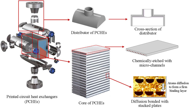
FIGURE 1. Structure of printed circuit heat exchangers (Heatric, 2008; Ma et al., 2015; Huang et al., 2019; Ma et al., 2022).
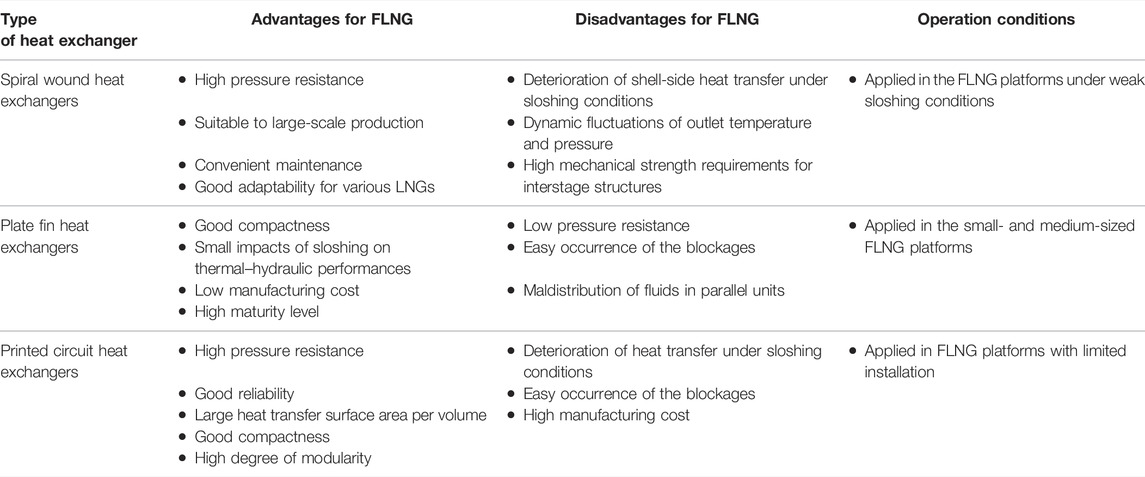
TABLE 1. Comparison of heat exchangers for FLNG (Hasan et al., 2009; Oh et al., 2009; Pacio and Dorao, 2011; Ma et al., 2016; Zheng et al., 2021; He et al., 2022; Ma et al., 2022).
The existing research studies on the PCHE applied in FLNG mainly include the mechanical performance, the thermal–hydraulic performance under stable conditions, and the thermal–hydraulic performance under sloshing conditions. The mechanical performance is the key factor to evaluate the reliability of PCHE, and the optimizations of the mechanical performance of PCHE have been performed based on the deformation analysis in the process of diffusion bonding under high-temperature conditions by former researchers (Yoon et al., 2017; Xu et al., 2022). The thermal–hydraulic performance under stable conditions is the basis of the PCHE design, and the related research studies cover the quantitative analysis of thermal–hydraulic characteristics of PCHEs with various structural parameters and the correlation development of thermal–hydraulic characteristics (Shin and No, 2017; Popov et al., 2019; Bohong Wang et al., 2021; Li and Yu, 2021; Jin et al., 2022; Yang et al., 2022; Zhou et al., 2022). The thermal–hydraulic performance under sloshing conditions determines the liquid production rate of FLNG, and the additional inertial forces caused by the sloshing of PCHE may result in the change of flow pattern, the misdistribution of gas and liquid, and the fluctuation of flow and thermal–hydraulic performances (Çarpinlioǧlu and Gündoǧdu, 2001; Ma et al., 2021).
The challenges to apply the PCHE in FLNG platforms mainly result from the following three aspects. Firstly, the structure design criteria of PCHEs applied in FLNG are unknown. The structure design criteria of PCHEs applied in FLNG are different from those applied in the onshore conditions, which needs to consider the operating conditions of FLNG platform and the marine conditions comprehensively. Secondly, the influencing mechanisms of the sloshing condition on the performances of PCHEs are unclear. The sloshing condition will lead to the fluctuation of the temperature and pressure and the misdistribution of gas and liquid among micro-channels of PCHEs, and it may change the flow pattern of the non-zeotropic working fluid as well as the mass and energy transfer in micro-channels, making it difficult to predict the mechanical and the thermal–hydraulic performance of PCHEs. Finally, the method of suppressing the adverse effects of sloshing conditions on the performances of PCHEs is uncertain. In the design of PCHE applied in FLNG, the adverse effects of sloshing conditions caused by winds and waves should be concerned, and the method of suppressing the adverse effects of sloshing conditions should be studied.
In this paper, the state of the development and the application of PCHEs in FLNG are reviewed, and the key issues for applying PCHEs in FLNG are analyzed, including the structure design criteria of PCHEs, the influence mechanism of sloshing, and the method of suppressing the adverse effects of sloshing conditions on the performances of PCHEs.
The structures of PCHEs are the key factors to determine heat transfer and pressure drop characteristics. The flow channel type is the basic structure parameter, and two types of flow channels including continuous flow channels and discontinuous flow channels are employed in PCHEs, as shown in Figure 2 (Chai and Tassou, 2020).
The continuous flow channels can be classified as the straight channel and the zigzag channel. The straight channel is the basic channel type, and the structural parameters of the straight channel include the typical equivalent hydraulic diameter (d), cross-section, transverse pitch (S), and vertical pitch (Aquaro and Pieve, 2007). The zigzag channel is the most widely used type of flow channel in PCHEs. Besides the structural parameters of the straight channel, the structural parameters of the zigzag channels include the zigzag angle and the zigzag pitch length (Bone et al., 2018), which determine the flow path and become more critical for the structural optimization of the zigzag channels. The cross-section shapes of both the straight channel and the zigzag channel include semicircular, rectangular, trapezoid, or elliptical.
The discontinuous flow channels include the S-shaped fin channel and the airfoil channel. The structural parameters of the S-shaped fin channel include the fin length (Lx), fin width (df), channel width (dy), and fin angle (φ) (Tsuzuki et al., 2009a). The structural parameters of the airfoil channel include the transverse pitch (La), staggered pitch (Lb), and longitudinal pitch (Lc) (Chu et al., 2017). Both the S-shaped fin channel and the airfoil channel show high heat transfer and low pressure drop, but the complex structures of discontinuous flow channels result in a much higher cost in the chemical etching process and poorer pressure resistance compared to those of continuous flow channels. Therefore, PCHEs with S-shaped fin channels and airfoil channels are still confined to the laboratory.
The existing research studies related to the heat transfer characteristics of PCHEs cover the quantitative analysis of heat transfer characteristics with various flow channel types and the correlation development of heat transfer characteristics. In the state of laminar flow, the impact of flow channel types on heat transfer characteristics of PCHEs is weak (Pra et al., 2008), while in the state of turbulent flow, the impact of flow channel types on heat transfer characteristics can be expressed as the Nusselt number (Kandlikar et al., 2006), and the expressions of various flow channel types are summarized as follows.
For PCHEs with straight channels, the main factors affecting the heat transfer characteristics are typical equivalent hydraulic diameters (d) and cross-section of channels (Haiyan Zhang et al., 2019; Zhao et al., 2019; Khalesi et al., 2020; Liu et al., 2020a; Han Wang et al., 2021). The heat transfer coefficients decrease significantly with the decrease of the typical equivalent hydraulic diameters of the channels (Liu et al., 2018; Yuandong Zhang et al., 2019). The impact of cross-section on heat transfer coefficients can be neglected with the same hydraulic diameter (Jeon et al., 2016; Tu and Zeng, 2020).
For PCHEs with zigzag channels, the critical factor of structure that affects the heat transfer characteristics is the zigzag angle (Bone et al., 2018; Bennett and Chen, 2019; Torre et al., 2021; Li Y. et al., 2022). A bigger zigzag angle will lead to a larger transverse velocity, which may promote the mixing of working fluid and thus improve the heat transfer performance; but overly high zigzag angles may increase the size of separation zones and result in the reduction of the heat transfer area and the pitch-averaged Nusselt number. The maximum heat transfer characteristic is achieved when the zigzag angle is 35°. The impact of various cross-section shapes with the same hydraulic diameter on heat transfer coefficients can be neglected for PCHEs with zigzag channels (Lee and Kim, 2013).
For PCHEs with S-shaped fin channels, the critical factors affecting the heat transfer characteristics include the fin angle and hydraulic diameter (Ngo et al., 2007; Tsuzuki et al., 2009b). The heat transfer coefficients increase slightly with the increase of fin angle, and the heat exchange capacity of PCHEs increases from 20 MW/m3 to 30 MW/m3 when the fin angle increases from 0 to 60° (Tsuzuki et al., 2007). The hydraulic diameter has a significant impact on the heat transfer characteristics, and the small hydraulic diameter will enhance the impacts on the heat transfer characteristics. The heat exchange capacity of PCHEs reduces from 55 MW/m3 to 20 MW/m3 when the hydraulic diameter increases from 0.5 to 1 mm, and the heat exchange capacity of PCHEs reduces by only 10 MW/m3 when the hydraulic diameter increases from 1 to 2 mm (Hu et al., 2018).
For PCHEs with airfoil channels, the factors affecting heat transfer characteristics include the staggered arrangement, transverse pitch, and longitudinal pitch (Yuandong Zhang et al., 2019; Lu et al., 2022; Wang et al., 2022). The staggered arrangement can be described quantitatively by staggered pitch. When the staggered pitch increases, the average heat transfer coefficients decrease slightly. When the transverse pitch decreases or the longitudinal pitch increases, the Nusselt number decreases as well. And the impacts of longitudinal pitch on heat transfer characteristics are enhanced when the staggered arrangement is sparser with small transverse pitch (Kim et al., 2015).
For PCHEs with straight channels, zigzag channels, S-shaped fin channels, and airfoil channels, the developed correlations of heat transfer characteristics by former researchers are summarized in Table 2.
The pressure drop characteristics of PCHEs mainly depend on the flow channels and can be described by friction factors f. The detailed impact of the structure parameters of various flow channels on the pressure drop is explained as follows.
For PCHEs with straight channels, the pressure drop of the heat exchanger is smallest among all types of continuous flow channels. The previous research studies show that the critical factor of the pressure drop of straight channels is the typical equivalent hydraulic diameter. The friction factor f increases with the reduction of the hydraulic diameter, and the friction factor f is approximately inversely proportional to the Reynolds number.
For PCHEs with zigzag channels, the critical factors affecting the pressure drop include the hydraulic diameter of the channel (Kim et al., 2010) and the zigzag angle (Chen et al., 2016; Chen et al., 2019). The friction factor f increases with the increase of zigzag angle and the decrease of the hydraulic diameter. When the zigzag angle is bigger than 15°, the friction factor f may increase sharply. For various cross-section shapes, i.e., semicircular, circular, trapezoidal, and triangular, it is indicated that PCHEs with a circular cross-section shape own the smallest friction factor, and PCHEs with a rectangular cross-section shape own the largest friction factor which is about 1.3 ∼ 1.6 times that with the other cross-section shapes (Jeon et al., 2016).
For PCHEs with S-shaped fin channels, the critical factors affecting the pressure drop include the fin angle and the hydraulic diameter. The friction factor increases significantly with the increase of the fin angle; the friction factor may increase by nearly 9 times as the fin angle increases from 0 to 60°, and the fin angle has more significant impacts on the pressure drop when the fin angle is larger than 30° (Tsuzuki et al., 2007). The friction factor decreases with the increase of the hydraulic diameter, and the friction factor may remain almost constant when the hydraulic diameter is larger than 1.1 mm (Hu et al., 2018).
For PCHEs with airfoil channels, the factors affecting the pressure drop include the transverse pitch and the longitudinal pitch (Fu et al., 2019; Zhao et al., 2020; Zhu et al., 2021). With the increase of the transverse pitch, the velocity distribution tends to be stable, and the effect of eddy region behind the airfoil fins is weakened, leading to the significant reduction of the total pressure drop (Chu et al., 2017). With the decrease of the longitudinal pitch, the channel width between adjacent fins becomes narrow, and the flow resistance increases significantly, leading to the reduction of the total pressure drop (Kim et al., 2015).
For PCHEs with straight channels, zigzag channels, S-shaped fin channels, and airfoil channels, the developed correlations of pressure drop are summarized in Table 3.
The PCHE with a compact structure, high efficiency, and good reliability has good application prospects in the FLNG platform. There have been a few applications of PCHEs in the FLNG platform worldwide, which are mainly designed by Heatric, and the application trend for PCHE deployment in oil and gas applications steadily grows (Heatric, 2019).
By now, PCHEs have been applied in the FLNG projects in some countries. For example, there are 18 PCHEs applied by Shell’s Prelude in the PFLNG 1 project. This FLNG facility with the length of 488 m and the width of 74 m is the largest floating offshore facility in the world (LNG World News, 2011), and it will be moored offshore at a distance of over 200 km from Northwest Australia, and the water depth is about 250 m. For the PFLNG 2 project, there are 10 PCHEs applied, and the gas–liquid separation device and headers are combined to replace the single separators in these PCHEs for improving the compactness of FLNG arrangement (LNG Industry, 2014).
However, there is no application of PCHEs in the FLNG platform in China. The existing applications of PCHEs focus on the onshore facilities. For example, the first application of PCHEs in the LNG field in China is the Liwan 3-1 gas field, and PCHEs are applied as compressor aftercoolers and dry and wet gas heat exchangers in the central processing platform located in a shallow water area. In this application case, PCHEs show the advantages of high efficiency, high temperature resistance, and high pressure resistance, and the volume and weight of PCHEs are five-quarters those of spiral wound heat exchangers with the same capacity. As the application of PCHEs is positive for compact equipment installation space, platform equipment hoisting, weight control, and subsequent maintenance, the FLNG development in China has been approved by the Ministry of Industry and Information Technology, and PCHEs will be used as cryogenic heat exchangers.
In order to apply PCHEs in FLNG platforms, three key problems are needed to be figured out. Firstly, the structure design criteria of PCHEs in FLNG should be developed, and the design criteria should be capable of reflecting the effects of the operating conditions. Secondly, the influencing mechanism of sloshing conditions on the performance of PCHEs should be studied as the sloshing conditions will lead to significant differences of PCHEs’ performance compared to that under onshore conditions. Finally, the method of suppressing the adverse effects of sloshing conditions on the performance of PCHEs should be developed for realizing the full potential of PCHEs.
The thermal and hydraulic performance of PCHEs depends on the structure of flow channels. The heat transfer and pressure drop characteristics of PCHEs with various flow channels, i.e., straight channels, zigzag channels, S-shaped fin channels, and airfoil channels, are compared, as shown in Figure 3.
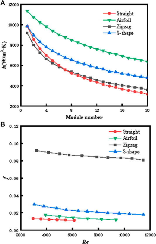
FIGURE 3. (A) Effect of channel structure on heat transfer coefficients (Yoon et al., 2014). (B) Effect of channel structure on Fanning friction factors (Ngo et al., 2006; Yoon et al., 2014).
For PCHEs with continuous flow channels, it can be found that PCHEs with straight channels have the smallest heat transfer capacity and the lowest pressure drop. The heat transfer performance of PCHEs with zigzag channels is significantly better than that with straight channels at the cost of larger pressure drop (Meshram et al., 2016; Saeed et al., 2020b). PCHEs with continuous flow channels including both straight and zigzag channels have high maturity level and low manufacturing cost.
For PCHEs with discontinuous flow channels, it can be found that the PCHEs with airfoil channels show best heat transfer and pressure drop performance (Zhang H. et al., 2021), and the pressure drop of PCHEs with airfoil channels is only 1/20 that with zigzag channels under the same heat transfer capacity (Kim et al., 2008). The S-shaped fin channels have worse heat transfer and pressure drop performance than the airfoil channels, but they have better performance than the zigzag channels. The pressure drop of PCHEs with S-shaped fin channels is only 1/10 that with zigzag channels under the same heat transfer capacity (Ngo et al., 2006).
Although the discontinuous flow channels have a better thermal–hydraulic performance compared to the continuous flow channels, the complex structures of the discontinuous flow channels may result in a high cost in the chemical etching process and poor pressure resistance of PCHEs (Lee et al., 2021). For designing the flow channels of PCHEs applied in FLNG, the operation conditions should be taken into account besides the thermal–hydraulic performance.
When the operational pressure of PCHEs is low and the working fluids are non-flammable, the airfoil channel is the best choice for PCHEs. The staggered arrangement of airfoil fins can reduce the pressure drop of heat exchanger. With the increasing transverse pitch or the decreasing longitudinal pitch, the comprehensive performance of heat exchanger can be improved with larger flow cross-section areas and shorter flow channels (Bartel et al., 2015).
When the operational pressure of PCHEs is high or the working fluids are flammable and explosive, the zigzag channel is the best choice for PCHEs. For zigzag channels with LNG as working fluids, there are periodic flow and heat transfer occurring in the cold and hot channels (Bai et al., 2020). Each local low-temperature region of LNG shown in temperature contours corresponds well to its accelerating core shown in velocity contours, as shown in Figure 4. This is because the periodic channel forces the fluid to change its flow direction, resulting in a centrifugal force. The shifting of accelerating core thins or even destructs the boundary layer, which is conducive to convective heat transfer. The best comprehensive performance is achieved when the channel bending angle is 15°, due to the criterion ξ = (Nu/Nu0)/(f/f0) for evaluating the thermal–hydraulic characteristics. When the channel bending angle rises from 0° to 15°, the Nusselt number increases obviously, and the Fanning friction factor has a little increase, indicating that the effect of bending angle on heat transfer is dominant. When the channel bending angle is larger than 15°, its effect on flow resistance is more significant.
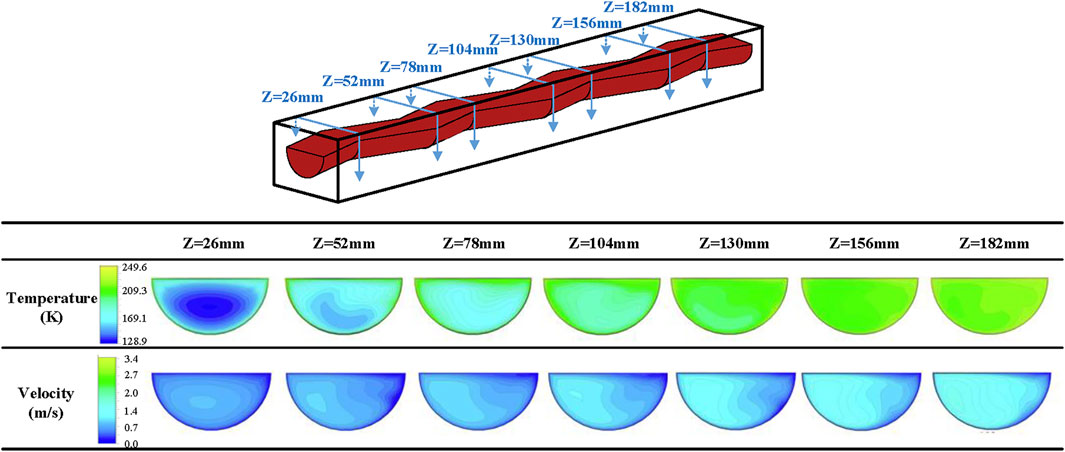
FIGURE 4. Flow and heat transfer characteristics of the zigzag-channel PCHE with LNG (Bai et al., 2020).
As the working fluid employed in FLNG is supercritical natural gas which is flammable and explosive, the flow channel applied in FLNG must meet the requirements of good pressure resistance capacity to ensure the reliability of PCHEs. Therefore, the zigzag channel is the recommended channel type of PCHEs in FLNG because the zigzag channel has better pressure resistance capacity compared to the S-shaped fin channel and the airfoil channel and better heat transfer performance compared to the straight channel.
The sloshing types can be classified into six independent motions, including three translational motions along the axis in three directions: sway, surge, and heave, and three rotational motions around the axis in three directions: roll, pitch, and yaw (Zheng et al., 2018b). As the heave, pitch, and roll motions have much greater effects than the others (Webb, 1981; Yan, 2017), the influencing mechanism of heave, pitch, and roll conditions on the performance of PCHEs should be studied.
For investigating the influencing mechanism of sloshing conditions, the thermal and hydraulic performance of PCHEs under various operating conditions, sloshing conditions, and structures will be analyzed, and the effects of sloshing conditions on the distribution and the flow pattern of working fluids as well as dynamic fluctuation will be proposed.
The sloshing conditions will lead the instantaneous thermal and hydraulic performance of PCHE to periodically fluctuate, and the fluctuation period of thermal and hydraulic performance is the same as the sloshing period. The reason is that the flow velocity of working fluid in PCHEs will periodically change under the additional force, resulting in the heat transfer coefficient and friction factor of the heat exchanger fluctuating with the sloshing period.
The factors that affect the overall performance of PCHE are as follows: 1) operating conditions of heat exchanger, including the fluid inlet temperature, inlet mass flux, and heat flux; 2) sloshing parameters, including the sloshing period and sloshing amplitude; and 3) the structure of heat exchangers.
The factors of operating conditions that affect the thermal and hydraulic performance of PCHE include the fluid inlet temperature, inlet mass flux, and heat flux.
The effects of fluid inlet temperature on thermal and hydraulic performance are shown in Figures 5A,B. The Nusselt number increases with the increase of the fluid inlet temperature, and the fluctuation degree of the Nusselt number gradually decreases by increasing inlet temperature. The heat transfer characteristics of the natural gas in the pseudocritical and subcritical zones were greatly affected by the rolling inertial force, whereas they were less affected in the supercritical zone (Pan Zhang et al., 2019). On the contrary, the friction factor decreases with the increase of the mass flux, and the fluctuation degree of the friction factor gradually decreases by increasing inlet temperature. The impacts of sloshing conditions on both the Nusselt number and the friction factor are weak when the temperature is above 210 K.
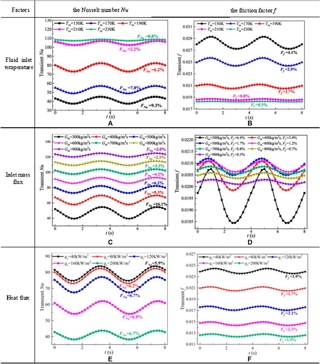
FIGURE 5. Effect of operating conditions on thermal and hydraulic performance (Chen et al., 2022).
The effects of inlet mass flux on thermal and hydraulic performance are shown in Figures 5C,D. The trend of Nusselt number rises with the increase of inlet mass flux, and the fluctuation degree of Nusselt number gradually decreases by increasing inlet mass flux. The maximum fluctuation is reduced from 16.1% to 2.0%, when the inlet mass flux increases from 300 to 900 kg/m2s. The friction factor increases firstly and then decreases with the increase of the inlet mass flux, and the fluctuation degree of friction decreases with the increase of the mass flux. The maximum average friction factor is achieved as 6.4% when the mass flux is 500 kg/m2s. And the maximum fluctuation drops from 6.4% to 0.5%, when the inlet mass flux increases from 300 to 900 kg/m2s.
The effects of the heat flux on thermal and hydraulic performance are shown in Figures 5E,F. The Nusselt number gradually decreases with the increase of heat flux, and the decreasing degree of Nusselt number gradually increases. The friction factor gradually increases by increasing heat flux, and the increasing degree of friction gradually increases. In addition, the fluctuation degrees of Nusselt number and friction almost stay steady with the increase of heat flux under the same rolling motion. It is concluded that heat flux has little effect on the fluctuation of convective heat transfer under the rolling condition.
The factors of sloshing conditions that affect the thermal and hydraulic performance of PCHE include the sloshing amplitude and sloshing period (Chen et al., 2022).
The effects of sloshing amplitude on thermal and hydraulic performance are shown in Figures 6A,B. The fluctuation degree of the Nusselt number will increase with the increase of the sloshing amplitude, and the largest fluctuations are 8.4% when the rolling amplitude is 20°. The fluctuation degree of friction factor also increases by increasing sloshing amplitude, and the largest fluctuation degree of friction factor is achieved as 2.4% when the rolling amplitude is 20°. The reason is that the larger rolling amplitude will make the greater angular velocity and angular acceleration, leading to a larger additional inertial force.
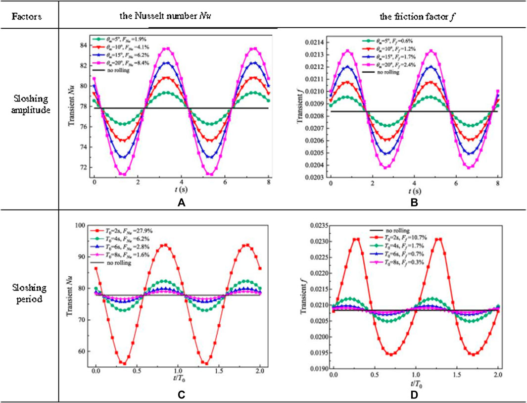
FIGURE 6. Effect of sloshing conditions on thermal and hydraulic performance (Chen et al., 2022).
The effects of sloshing period on thermal and hydraulic performance are shown in Figures 6C,D. The fluctuations of the Nusselt number increase with the reduction of sloshing period; this is because the angular velocity and angular acceleration are greater when the rolling period is smaller, which leads to a larger additional inertial force. The maximum fluctuation degree of Nusselt number is achieved as 27.9% when the rolling period is 2 s. The fluctuations of friction factor increase with the reduction of sloshing period. When the rolling period is 2 s, the maximum fluctuation of friction factor is achieved as 10.7% and the ratio of the friction factor in a rolling condition fr to the steady friction factor fs is as large as 1.28; when the rolling period was greater than 2 s, the ratio fr/fs along the PCHE channel tended to remain unchanged with the variation in the rolling period and amplitude.
For the structure of heat exchanger, the heat transfer and pressure drop performances of PCHEs with straight channels and airfoil channels in rolling motion have been investigated (shown in Figure 7). Under sloshing conditions, the average heat transfer coefficient and pressure drop factor of PCHEs with straight channels remain almost constant. The average heat transfer coefficients and pressure drop of the airfoil channels are significantly greater than those under stable conditions (Tang et al., 2020). Thus, the crest point increases and the trough point decreases. This is because the influences of the rolling motion on the thermal performance have two aspects: the uniformity of the flow velocity becomes bad and, thus, the thermal performance is weakened. However, the rolling motion can cause an additional inertia to increase the flow turbulence, which can enhance the heat transfer. For the airfoil channels, the influence of flow turbulence is greater and has a positive effect on heat transfer enhancement.

FIGURE 7. Effect of heat exchanger structure on thermal and hydraulic performance (Chen et al., 2022; Tang et al., 2020).
The sloshing of PCHE makes the working fluids in a single channel maldistributed. The cause of the maldistribution is that the sloshing of PCHE will produce additional inertial forces on the gas–liquid mixture in a single channel, resulting in the working fluid accumulating at one side of the channel due to inclining of heat exchanger, and the maldistributions are even more serious as the inclined angle increases (Brian, 2002; Duan et al., 2016; Ren et al., 2018a).
The flow characteristics of the working fluid of PCHE will periodically fluctuate with the sloshing conditions. Under a period of rolling motion, the flow in the channels is mainly affected by the additional inertial forces and the gravity component, resulting in the sinusoidal periodic fluctuation of mainstream acceleration and the non-sinusoidal periodic fluctuation of radial acceleration. The influences of sloshing conditions on acceleration in the mainstream and radial flows are explained as follows.
For the sloshing conditions on mainstream acceleration, the instantaneous flow characteristics are determined by the time in a sloshing period, as shown in Figure 8 (Chen et al., 2022). When rolling time is between 0 and Tr/4, the relative velocity of the main flow decreases because the fluid is subjected to an increasing additional force in the opposite direction of the main flow. When rolling time is Tr/4, the channel is at the position of the maximum positive rolling angle, resulting in the relative velocity of fluid and channel to be relatively small. When rolling time is between Tr/4 and 3 Tr/4, the velocity of the fluid increases because the fluid is subjected to an increasing additional force in the positive direction of the main flow. When rolling time is 3 Tr/4, the channel is at the position of the maximum negative rolling angle, resulting in the flow velocity to be relatively large. When the rolling time is between 3 Tr/4 and Tr, the relative velocity of the main flow decreases due to the decrease in acceleration. It is indicated that the maximum and minimum values of velocities appear slightly later than those of additional force, since the minimum additional force is at Tr/4 and maximum additional force is at 3 Tr/4. The reason is that there is a certain response time between the additional force and the velocity change in the mainstream.
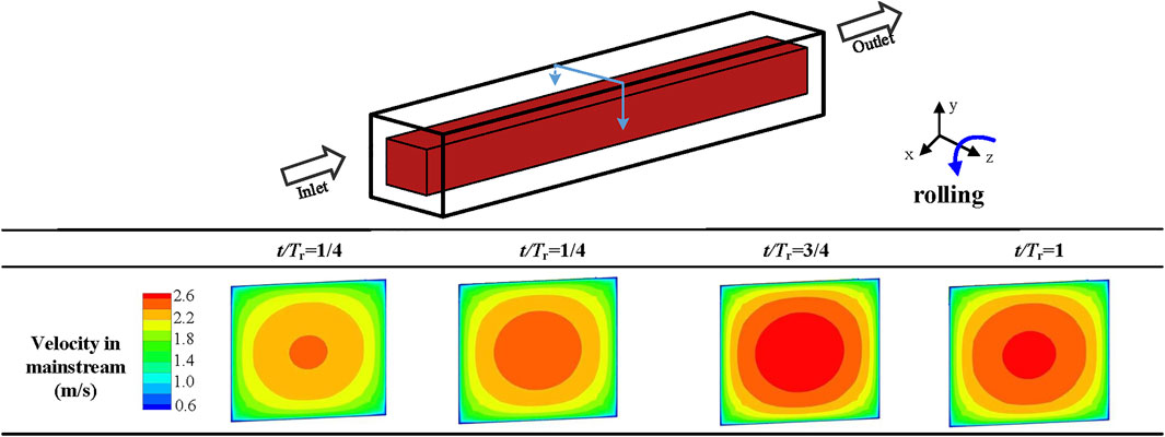
FIGURE 8. Effect of sloshing on the flow field in the mainstream direction (Chen et al., 2022).
For the sloshing conditions on radial acceleration, the instantaneous flow characteristics are determined by the time in a sloshing period, as shown in Figure 9 (Ma et al., 2021). The velocity of natural gas is lower near a channel wall but higher in the main flow area. Thus, the effect of the force on the natural gas in these two areas was different, which caused natural mixing under the influence of the force. When rolling time is 1/4 Tr, the main flow area swung to the left side under the inertial force, and three vortices appeared. When rolling time is 1/2 Tr, the number of vortices reduced to two. When rolling time is Tr, two vortices distributed on the left and right sides. The flow field was the most disordered and had the highest increase in heat transfer when rolling time is 1/4 Tr and 3/4 Tr.
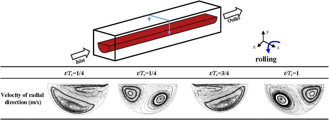
FIGURE 9. Effect of sloshing on the flow field in the radial direction (Ma et al., 2021).
The factors that affect the two-phase distribution of working fluids in a single channel include the mass flux and sloshing parameters. The impact on the performance of PCHEs can be expressed by the heat transfer coefficients and pressure drop of the heat exchangers. The influence mechanism of sloshing conditions on PCHEs is similar to that on the shell side of the spiral wound heat exchangers.
For mass flux, the influence of sloshing conditions on heat transfer and pressure drop characteristics is roughly inversely proportional to mass flux (Ding et al., 2018). When the mass flux is ranging from 80 to 100 kg/(m2·s), the influence of rolling is approximately equivalent. The fluctuation degrees of heat transfer and pressure drop characteristics decrease with the increasing vapor quality. The possible reason is that the increasing vapor quality leads channels to be almost filled with vapor phase, resulting in the effect of maldistribution of two-phase flow to be smaller at high vapor quality. With the increasing vapor quality, the pressure drop gradient gradually increases, and the heat transfer coefficient first increases and then decreases sharply at high vapor quality (Ren et al., 2018b).
For sloshing parameters, the existing literature studies have compared the effects of three sloshing motions, i.e., heave, pitch, and roll, on the performance of the heat exchangers. Heave motion has the greatest impact on the heat transfer coefficients and pressure drop of the heat exchanger, followed by roll and pitch (Zhu et al., 2017). With the increase of sloshing amplitude or the decrease of sloshing period, the fluctuation degrees of heat transfer coefficients and pressure drop increase significantly, and the effects of sloshing period are weaker than those of sloshing amplitude (Sun et al., 2017).
The sloshing makes the working fluids among multiple channels maldistributed due to the interaction between the gas and liquid phases under the sloshing motions, as shown in Figure 10. It is observed that the mixture distribution performance is the best among three kinds of standard deviations of the flow rate, and liquid distribution uniformity is better than that of gas. Gas distribution has the lowest performance under steady and heave conditions, while liquid and gas–liquid mixture distribution performances are the lowest under roll condition, which may result in significant deterioration of heat transfer and safety potential (Zhu et al., 2019).
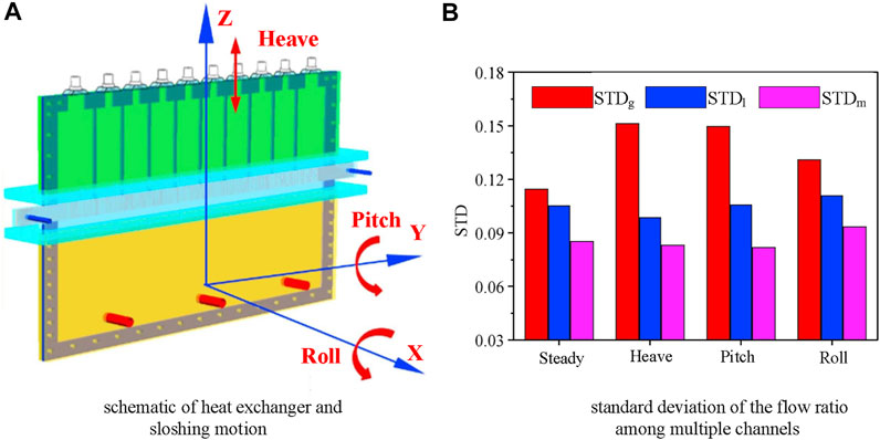
FIGURE 10. Distribution of working fluids among multiple channels (Zheng et al., 2019). (A) Schematic of the heat exchanger and sloshing motion. (B) Standard deviation of the flow ratio among multiple channels.
The factors that affect the two-phase distribution of working fluids among multiple channels include the mass flux, sloshing parameters, and structure of heat exchangers. The impact on the performance of PCHEs can be expressed by the heat transfer coefficients and pressure drop of the heat exchangers. The influence mechanism of sloshing conditions on PCHEs is similar to that on the plate fin heat exchangers.
For mass flux of liquid and gas phases, the increasing mass flux is helpful to the gas and liquid distribution uniformity (Zheng et al., 2019). With the increasing vapor quality, the flow difference in the channels becomes increasingly smaller. And the increase of vapor quality will easily affect the gas distribution than the liquid one. The increasing vapor quality will improve the gas distribution performance correspondingly but exercised less influence on the liquid distribution.
For sloshing parameters, the sloshing motion can be divided into a single sloshing motion and coupling of multiple sloshing motions. Under the single sloshing motion, the gross tendency of distribution is identical in all sloshing conditions, and the liquid uniformity under roll condition is worst for all conditions. Under the coupling of multiple sloshing motions, the distribution of gas–liquid mixture will be different from that under a single sloshing form, and the comprehensive impacts of multiple sloshing motions on the heat exchanger cannot be recognized as superposition of the individual effects of each sloshing motion. With the increase of sloshing period, the liquid distribution performance correspondingly improves, and the gas distribution performance remains the same. With the increase of sloshing amplitude, the non-uniformity of liquid phase and gas phase flows increases, and liquid distribution performance is better than gas distribution performance at low vapor quality (Zheng et al., 2018b).
The structure of heat exchangers will influence the pressure drop of each channel and then influence the distribution of gas–liquid mixture among multiple channels (Strobel and Mortean, 2021). The pressure drop of the fluid of a single channel includes the pressure drop when entering the channel from the inlet header, the pressure drop along the channel, and the pressure drop loss when entering the outlet header from the channel. The difference in inlet and outlet local pressure drops causes the differences in channel pressure drop because the total pressure drop is the same for each channel, which in turn leads to the difference in flow rate. Therefore, the flow non-uniformity can be reduced by increasing the proportion of loss along the channel, and the loss along the path increases linearly with an increase in channel length, so it can be inferred that the increase in channel length can improve the flow uniformity of the PCHE. When the dimensionless length of the channel (L/Dh)cr exceeds 500, the non-uniformity of flow can be neglected at a total flow rate of 0.12 kg/s (Ma et al., 2020).
The sloshing of PCHE makes the flow pattern change along the channels, leading to the periodic fluctuation of heat transfer and pressure drop characteristics (Tan et al., 2009). However, no study has been reported concerning the influence of the sloshing conditions on the flow pattern of PCHEs, so that the impact of the flow pattern on the thermal and hydraulic performance of PCHE is uncertain. The open literature studies related to sloshing conditions on the flow pattern focus on the tubes with larger diameters. For example, Yan and Yu (2008) investigated the influence mechanism of rolling motion on the flow and heat transfer characteristics in a single tube, and the results show the sloshing conditions will enhance turbulence in the flow field and make the velocity distributions fluctuate, leading to the natural mixing in the radial direction and better heat transfer performance. Wang and Zhang (2005) and Yu et al. (2004) proposed that the flow will turn to be pulsatile flow under sloshing conditions, which has great impacts on the flow and heat transfer characteristics. However, there is no unified conclusion whether the effect of pulsating flow on heat transfer characteristics is enhanced or weakened.
The heat transfer deterioration under sloshing conditions mainly results from the maldistribution of working fluids. The existing methods for avoiding or suppressing the maldistribution of working fluids are summarized as follows: 1) structural optimization of distributor; 2) shape optimization of inlet part in heat exchange plates; 3) conducting transverse bypass configuration; and 4) dimple-shaped channel development. Among all these methods, only the structural optimization of distributor is specially developed for suppressing the adverse effects of sloshing conditions on the distribution of working fluids. The other three methods are proposed based on stable conditions, which can also provide a basis for avoiding or suppressing the maldistribution of working fluids under sloshing conditions.
The structural optimization of distributor can improve the distribution uniformity of working fluids among multiple channels (Li et al., 2015). The methods of distributor structural optimization include “distribution prior mixing” (Yuan et al., 2016) and inlet header optimization (Anbumeenakshi and Thansekhar, 2016). The method known as “distribution prior mixing” is to make gas and liquid phases firstly separate and then individually feed into the heat exchanger from two separate inlets, as shown in Figure 11. The research results show that the liquid distribution improves because the liquid is directly distributed through the liquid channels of the distributor and has no contact with the gas during the distribution. And the new distributor exhibits better sloshing resistance due to the small interaction between the two phase flows. Since the liquid phase flows through the liquid channels, the velocity is high enough to decrease the effects of the sloshing angles and sloshing displacements. Thus, the method of “distribution prior mixing” is an efficient way to defeating sloshing in heat exchangers. For the inlet header optimization, the flow non-uniformity of a straight-channel PCHE with four different inlet headers, i.e., the rectangular inlet header, parabolic inlet header, trapezoidal inlet header, and hyperbolic inlet header, is analyzed (Chu et al., 2018). The flow non-uniformity of the PCHE with the hyperbolic inlet header is much lower than the others. Strong recirculation regions can be found in the trapezoidal and parabolic inlet headers resulting in reduced fluid flow into the peripheral channels, as shown in Figure 12. Moreover, the velocity gradient at the pre-entry position is much worse in the rectangular inlet header. This is due to the large internal volume of rectangular inlet header which may redirect the fluid impacting the wall. Meanwhile, the hyperbolic inlet header is designed based on the streamline profile, resulting in only a small recirculation area in the header. The fluid flowing toward the peripheral channels has no backflow route or area to recirculate.
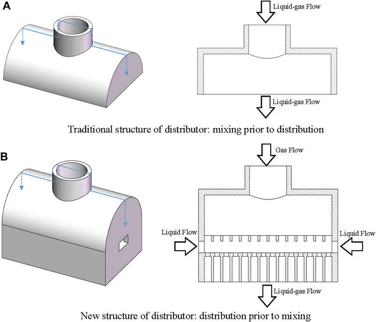
FIGURE 11. Comparison of traditional and new structures of distributors (Yuan et al., 2016). (A) Traditional structure of the distributor: mixing prior to distribution. (B) New structure of the distributor: distribution prior to mixing.
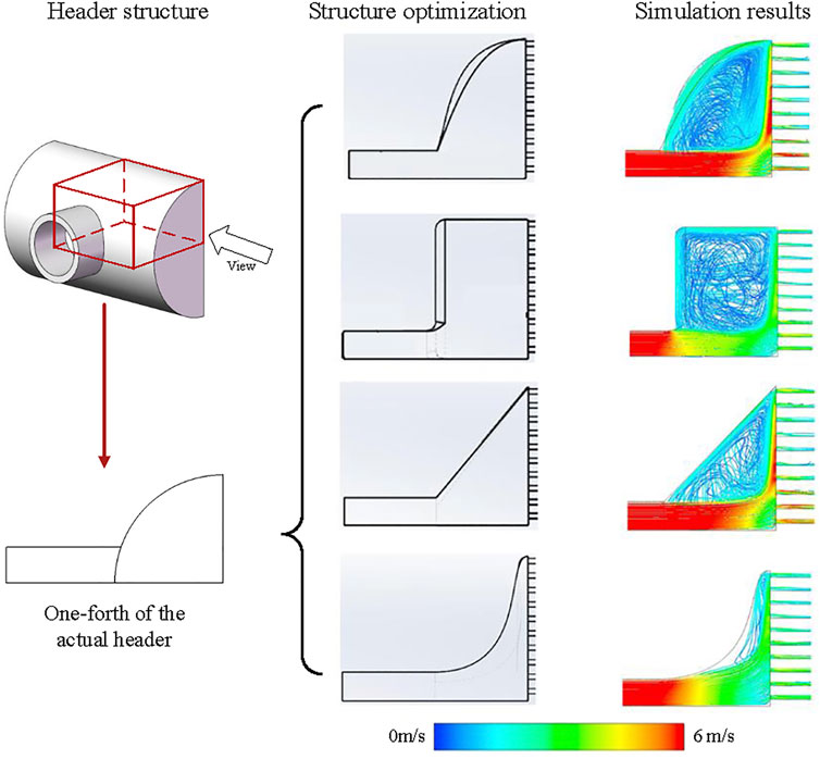
FIGURE 12. Schematic diagram of inlet header optimization (Chu et al., 2018).
Shape optimization of inlet part in heat exchanger plates can improve the distribution uniformity among multiple channels under stable conditions (Koo et al., 2014; Pasquier et al., 2016). Compared with the distributor, the shape optimization of inlet part (as shown in Figure 13) can improve the compactness, reduce the heat exchanger volume, and improve the distribution uniformity under low pressure drop. The main structural parameters of the inlet plenum include the width of inlet pipes and angle and radius of curvature of inlet plenum. With the increase of the width of inlet pipes, the flow uniformity first increases and then decreases, and the best value is obtained when the width of inlet pipes is between 2.5 and 2.6 mm. When the angle of the inlet plenum is 30°, the flow uniformity of working fluids is the best. When the radius of curvature of the inlet plenum ranges from 40 to 120 mm, the flow uniformity will increase with the increase of the radius of curvature, and the best performance with the lowest pressure drop will be obtained as the radius of curvature is 120 mm. By optimizing the shape parameters of inlet plenum in PCHEs, the flow standard deviation of the non-dimensional mass flow parameter can be reduced below 0.06. Shape optimization of inlet part can be combined with other methods such as transverse bypass configuration to further improve the distribution characteristics.
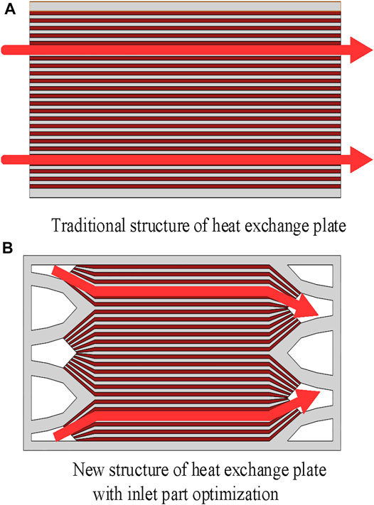
FIGURE 13. Structure optimization of the inlet part in the heat exchange plate. (A) Traditional structure of the heat exchange plate. (B) New structure of the heat exchange plate with inlet part optimization.
PCHEs with transverse bypass configuration can also improve the flow uniformity among multiple channels under stable conditions (Jung et al., 2012). The transverse bypass configuration (as shown in Figure 14) can make the working fluids flow freely between adjacent channels, leading to the redistribution in the heat exchanger and reducing the non-uniformity caused by different pressure boundary conditions. At the same time, PCHEs with transverse bypass configuration can operate normally when the flow channels are partially blocked, contributing to the improvement of defect tolerance in manufacturing and application and reduction of the risks and losses caused by frequent start-up and shutdown (Baek et al., 2012).
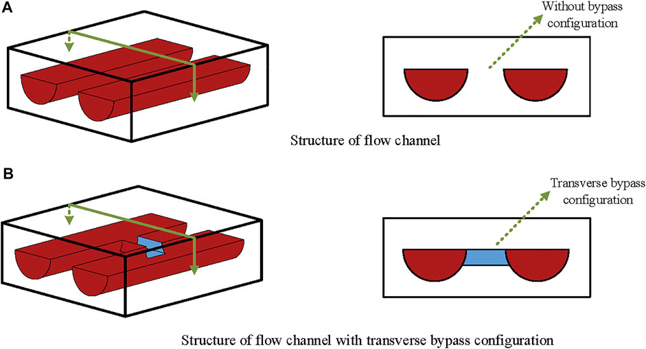
FIGURE 14. Structure of transverse bypass configuration. (A) Structure of the flow channel. (B) Structure of the flow channel with transverse bypass configuration.
PCHEs with dimple-shaped channels can improve the flow uniformity in a single pipe under stable conditions (Aneesh et al., 2016; Nagarajan et al., 2014). The hemispherical dimple in the channel (as shown in Figure 15) can break the viscous boundary layer by periodical restarts, resulting in a flow separation and vortex formation in the downstream wake region. Thus, the heat transfer characteristics of dimple-shaped channels are enhanced, and the friction factors for the dimple channel deteriorate, resulting from the vortex and the increase of turbulent kinetic energy. For example, when the mass flow rate is 1,000 kg/m2s and the inlet temperature is 245 K, the heat transfer enhanced effect is about 50%, and the friction factor is just deteriorated 15% (Chen et al., 2020). The comprehensive thermal performance evaluated by PEC (Webb, 1981) is positive, indicating that dimple-shaped channels have a greater effect on the enhancement of heat transfer than on deterioration of friction factor.
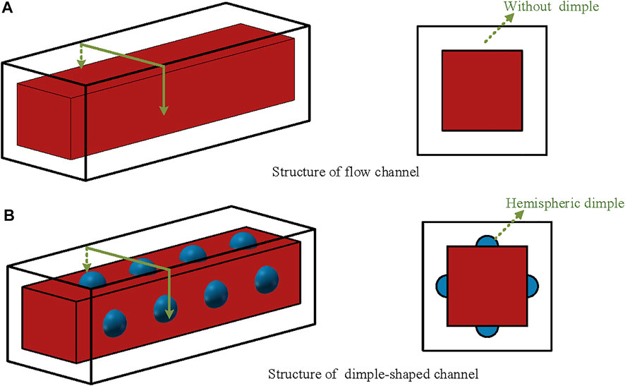
FIGURE 15. Structure of dimple-shaped flow channels. (A) Structure of the flow channel. (B) Structure of the dimple-shaped channel.
For the structural optimization shown in Figures 14, 15, the transverse bypass configuration and hemispheric dimple will grow a number of sharp corners of the channels, which are the stress concentrations in the heat exchanger (Lee and Lee 2014). Furthermore, the tip radius of the hemispheric dimple is smaller than that of the channel without dimple, leading to the increase of the maximum stress (Mahajan and Devi, 2018). The structural optimization may lead to low strength to endure the high pressure, so whether it can be applied in PCHEs for FLNG still needs further research studies based on the pressure condition and strength requirement.
Printed circuit heat exchangers (PCHEs) with a compact structure, high efficiency, and good reliability have good application prospects in the floating liquefied natural gas (FLNG) platform. In this paper, the research status of PCHE is reviewed, including the classification of PCHE structure, heat transfer characteristics, and resistance characteristics. The application status of PCHE in FLNG is summarized. In order to achieve high thermal–hydraulic performance of PCHEs applied in FLNG, the following key technologies should be developed:
1) The structure design criteria of PCHEs should be developed. The thermal and hydraulic performance of PCHEs depends on the structure of flow channels. The heat transfer characteristics can be strengthened by changing the structure of flow channels; however, the pressure drop generally increases as well. And the complexity of the structural will result in a much higher cost and poor pressure resistance structure. Therefore, it is necessary to comprehensively consider the operation conditions and the thermal–hydraulic characteristics of PCHEs with various flow channels.
2) The influence mechanism of sloshing condition on performances of PCHEs should be investigated, including the numerical simulation of flow characteristics with multiple degrees of freedom, establishment of the heat and mass transfer model among multiple channels under sloshing conditions, and development of the correlation of heat transfer and pressure drop in micro-channels for FLNG.
3) The methods of suppressing the adverse effects of sloshing conditions on the performance of PCHEs should be developed, including investigation of heat and mass transfer law of multiphase flow under different sizes of micro-channel, the development of measures to enhance the heat transfer characteristics in micro-channels under extreme sea conditions, and the design of a new micro-channel structure with low resistance and high efficiency to meet the requirements of FLNG.
4) The suggestions of next-step research directions concerning PCHEs applied in FLNG are summarized as follows. Firstly, the dynamic variation of the additional inertia force caused by sloshing on the heat transfer and pressure drop in micro-channels should be analyzed. Then, more experimental and numerical studies are required for natural gas at supercritical temperatures and pressures, which may experience a drastic property-variation process during liquefaction. Based on the study data, the universal correlations that are able to cover a wide range of geometry and flow parameters of PCHEs should be developed. Finally, the optimization of the structure of PCHEs should be conducted, in order to improve the performance and reduce the overall cost of manufacture of PCHEs applied in FLNG.
LX investigated and curated the data and wrote the original draft. DZ and ZL reviewed and edited the paper. GD was involved in project supervision and administration and funding acquisition.
The authors declare that the research was conducted in the absence of any commercial or financial relationships that could be construed as a potential conflict of interest.
All claims expressed in this article are solely those of the authors and do not necessarily represent those of their affiliated organizations, or those of the publisher, the editors, and the reviewers. Any product that may be evaluated in this article, or claim that may be made by its manufacturer, is not guaranteed or endorsed by the publisher.
The authors gratefully acknowledge the support from the National Nature Science Foundation of China (Grant No. 51906135), the Startup Fund for Youngman Research at SJTU (Grant No. 18X100040064), and the Special Fund of Jiangsu Province for the Transformation of Scientific and Technological Achievements (Grant No. BA2019053).
Alvarez, R. C., Sarmiento, A. P. C., Cisterna, L. H. R., Milanese, F. H., and Mantelli, M. B. H. (2021). Heat Transfer Investigation of a 90° Zigzag Channel Diffusion-Bonded Heat Exchanger. Appl. Therm. Eng. 190, 116823. doi:10.1016/j.applthermaleng.2021.116823
Anbumeenakshi, C., and Thansekhar, M. R. (2016). Experimental Investigation of Header Shape and Inlet Configuration on Flow Maldistribution in Microchannel. Exp. Therm. Fluid Sci. 75, 156–161. doi:10.1016/j.expthermflusci.2016.02.004
Aneesh, A. M., Sharma, A., Srivastava, A., Vyas, K. N., and Chaudhuri, P. (2016). Thermal-hydraulic Characteristics and Performance of 3D Straight Channel Based Printed Circuit Heat Exchanger. Appl. Therm. Eng. 98 (5), 474–482. doi:10.1016/j.applthermaleng.2015.12.046
Aquaro, D., and Pieve, M. (2007). High Temperature Heat Exchangers for Power Plants: Performance of Advanced Metallic Recuperators. Appl. Therm. Eng. 27 (2), 389–400. doi:10.1016/j.applthermaleng.2006.07.030
Bae, S. J., Kwon, J., Kim, S. G., Son, I.-w., and Lee, J. I. (2019). Condensation Heat Transfer and Multi-phase Pressure Drop of CO2 Near the Critical point in a Printed Circuit Heat Exchanger. Int. J. Heat Mass Transfer 129, 1206–1221. doi:10.1016/j.ijheatmasstransfer.2018.10.055
Baek, S., Kim, J.-H., Jeong, S., and Jung, J. (2012). Development of Highly Effective Cryogenic Printed Circuit Heat Exchanger (PCHE) with Low Axial Conduction. Cryogenics 52 (7-9), 366–374. doi:10.1016/j.cryogenics.2012.03.001
Bai, J., Pan, J., He, X., Wang, K., Tang, L., and Yang, R. (2020). Numerical Investigation on thermal Hydraulic Performance of Supercritical LNG in Sinusoidal Wavy Channel Based Printed Circuit Vaporizer. Appl. Therm. Eng. 175, 115379. doi:10.1016/j.applthermaleng.2020.115379
Bartel, N., Chen, M., Utgikar, V. P., Sun, X., Kim, I.-H., Christensen, R., et al. (2015). Comparative Analysis of Compact Heat Exchangers for Application as the Intermediate Heat Exchanger for Advanced Nuclear Reactors. Ann. Nucl. Energ. 81, 143–149. doi:10.1016/j.anucene.2015.03.029
Bennett, K., and Chen, Y.-t. (2019). A Two-Level Plackett-Burman Non-geometric Experimental Design for Main and Two Factor Interaction Sensitivity Analysis of Zigzag-Channel PCHEs. Therm. Sci. Eng. Prog. 11, 167–194. doi:10.1016/j.tsep.2019.03.020
Bennett, K., and Chen, Y.-t. (2020). Thermal-hydraulic Correlations for Zigzag-Channel PCHEs Covering a Broad Range of Design Parameters for Estimating Performance Prior to Modeling. Therm. Sci. Eng. Prog. 17, 100383. doi:10.1016/j.tsep.2019.100383
Bone, V., Mcnaughton, R., Kearney, M., and Jahn, I. (2018). Methodology to Develop Off-Design Models of Heat Exchangers with Non-ideal Fluids. Appl. Therm. Eng. 145 (25), 716–734. doi:10.1016/j.applthermaleng.2018.09.082
Brian, W. (2002). “Effects of Tilt and Motion on LNG and GTL Process Equipment for Floating Production,” in GPA Europe Annal Conference Warsaw, Poland, September 1, 2002.
Cao, L., Liu, J., Li, R., Huang, S., Zhang, F., and Xu, X. (2016). Experimental Study on the Mixed Refrigerant Heat Transfer Performance in a Plate-Fin Heat Exchanger during a Single-Stage Cryogenic Cycle. Appl. Therm. Eng. 93, 1074–1090. doi:10.1016/j.applthermaleng.2015.10.026
Çarpinlioǧlu, M. Ö., and Gündoǧdu, M. Y. (2001). A Critical Review on Pulsatile Pipe Flow Studies Directing towards Future Research Topics. Flow. Meas. Instrum. 12 (3), 163–174. doi:10.1016/S0955-5986(01)00020-6
Chai, L., and Tassou, S. A. (2020). A Review of Printed Circuit Heat Exchangers for Helium and Supercritical CO2 Brayton Cycles. Therm. Sci. Eng. Prog. 18, 100543. doi:10.1016/j.tsep.2020.100543
Chang, H.-M., Lim, H. S., and Choe, K. H. (2012). Effect of Multi-Stream Heat Exchanger on Performance of Natural Gas Liquefaction with Mixed Refrigerant. Cryogenics 52 (12), 642–647. doi:10.1016/j.cryogenics.2012.05.014
Chen, M., Sun, X., Christensen, R. N., Skavdahl, I., Utgikar, V., and Sabharwall, P. (2016). Pressure Drop and Heat Transfer Characteristics of a High-Temperature Printed Circuit Heat Exchanger. Appl. Therm. Eng. 108 (5), 1409–1417. doi:10.1016/j.applthermaleng.2016.07.149
Chen, M., Sun, X., and Christensen, R. N. (2019). Thermal-hydraulic Performance of Printed Circuit Heat Exchangers with Zigzag Flow Channels. Int. J. Heat Mass Transfer 130, 356–367. doi:10.1016/j.ijheatmasstransfer.2018.10.031
Chen, Y., Liu, Z., and He, D. (2020). Numerical Study on Enhanced Heat Transfer and Flow Characteristics of Supercritical Methane in a Square Mini-Channel with Dimple Array. Int. J. Heat Mass Transfer 158, 119729. doi:10.1016/j.ijheatmasstransfer.2020.119729
Chen, Y., Ma, Y., Liu, X., and He, D. (2022). Effect of Rolling Motion with Large Radius on Flow and Heat Transfer Characteristics of Supercritical Methane in a Mini Channel. Appl. Therm. Eng. 203, 117929. doi:10.1016/j.applthermaleng.2021.117929
Cheng, K., Zhou, J., Huai, X., and Guo, J. (2021). Experimental Exergy Analysis of a Printed Circuit Heat Exchanger for Supercritical Carbon Dioxide Brayton Cycles. Appl. Therm. Eng. 192, 116882. doi:10.1016/j.applthermaleng.2021.116882
Chong, Z. R., Yang, S. H. B., Babu, P., Linga, P., and Li, X.-S. (2015). Review of Natural Gas Hydrates as an Energy Resource: Prospects and Challenges. Appl. Energ. 162, 1633–1652. doi:10.1016/j.apenergy.2014.12.061
Chu, W.-x., Li, X.-h., Ma, T., Chen, Y.-t., and Wang, Q.-w. (2017). Experimental Investigation on SCO2-Water Heat Transfer Characteristics in a Printed Circuit Heat Exchanger with Straight Channels. Int. J. Heat Mass Transfer 113, 184–194. doi:10.1016/j.ijheatmasstransfer.2017.05.059
Chu, W.-x., Bennett, K., Cheng, J., Chen, Y.-t., and Wang, Q.-w. (2018). Numerical Study on a Novel Hyperbolic Inlet Header in Straight-Channel Printed Circuit Heat Exchanger. Appl. Therm. Eng. 146, 805–814. doi:10.1016/j.applthermaleng.2018.10.027
de la Torre, R., François, J.-L., and Lin, C.-X. (2021). Optimization and Heat Transfer Correlations Development of Zigzag Channel Printed Circuit Heat Exchangers with Helium Fluids at High Temperature. Int. J. Therm. Sci. 160, 106645. doi:10.1016/j.ijthermalsci.2020.106645
Deng, T., Zhu, Z., Li, X., Ma, T., and Wang, Q. (2020). Experimental Study on Electrochemical Etching for Titanium Printed Circuit Heat Exchanger Channels. J. Mater. Process. Technol. 282, 116669. doi:10.1016/j.jmatprotec.2020.116669
Ding, C., Hu, H., Ding, G., Chen, J., Mi, X., and Yu, S. (2018). Influences of Tube Pitches on Heat Transfer and Pressure Drop Characteristics of Two-phase Propane Flow Boiling in Shell Side of LNG Spiral Wound Heat Exchanger. Appl. Therm. Eng. 131 (25), 270–283. doi:10.1016/j.applthermaleng.2017.12.020
Duan, Z., Ren, T., Ding, G., Chen, J., and Pu, H. (2016). A Dynamic Model for FLNG Spiral Wound Heat Exchanger with Multiple Phase-Change Streams Based on Moving Boundary Method. J. Nat. Gas Sci. Eng. 34, 657–669. doi:10.1016/j.jngse.2016.07.036
Fu, Q., Ding, J., Lao, J., Wang, W., and Lu, J. (2019). Thermal-hydraulic Performance of Printed Circuit Heat Exchanger with Supercritical Carbon Dioxide Airfoil Fin Passage and Molten Salt Straight Passage. Appl. Energ. 247, 594–604. doi:10.1016/j.apenergy.2019.04.049
Ghorbani, B., Hamedi, M. H., Amidpour, M., and Shirmohammadi, R. (2017). Implementing Absorption Refrigeration Cycle In Lieu of DMR and C3MR Cycles in the Integrated NGL, LNG and NRU Unit. Int. J. Refrig. 77, 20–38. doi:10.1016/j.ijrefrig.2017.02.030
Han, Z., Guo, J., Zhang, H., Chen, J., Huai, X., and Cui, X. (2021). Experimental and Numerical Studies on Novel Airfoil Fins Heat Exchanger in Flue Gas Heat Recovery System. Appl. Therm. Eng. 192, 116939. doi:10.1016/j.applthermaleng.2021.116939
Hasan, M. M. F., Karimi, I. A., Alfadala, H. E., and Grootjans, H. (2009). Operational Modeling of Multistream Heat Exchangers with Phase Changes. Aiche J. 55 (1), 150–171. doi:10.1002/aic.11682
He, T., Karimi, I. A., and Ju, Y. (2018). Review on the Design and Optimization of Natural Gas Liquefaction Processes for Onshore and Offshore Applications. Chem. Eng. Res. Des. 132, 89–114. doi:10.1016/j.cherd.2018.01.002
He, T., Ma, H., Ma, J., Mao, N., and Liu, Z. (2021). Effects of Cooling and Heating Sources Properties and Working Fluid Selection on Cryogenic Organic Rankine Cycle for LNG Cold Energy Utilization. Energ. Convers. Manage. 247, 114706. doi:10.1016/j.enconman.2021.114706
He, N., Chen, Y., Yu, S., Yan, Y., Zhang, M., and Song, J. (2022). Effect of Winding Angles on Flow and Heat Transfer Characteristics in the Shell Side of Spiral Wound Heat Exchangers. Therm. Sci. Eng. Prog. 29, 101226. doi:10.1016/j.tsep.2022.101226
Heatric (2008). Website of Heatric Division of Meggitt. Available at: https://www.heatric.com/(Accessed, , 2008).
Heatric (2019). Oil & Gas Processing. Available at: https://www.heatric.com/heat-exchangers/industry-applications/oil-gas-processing/(Accessed June 02, 2019).
Hu, H., Yang, G., Ding, G., Chen, J., Yang, W., and Hu, S. (2018). Heat Transfer Characteristics of Mixed Hydrocarbon Refrigerant Flow Condensation in Shell Side of Helically Baffled Shell-And-Tube Heat Exchanger. Appl. Therm. Eng. 133 (25), 785–796. doi:10.1016/j.applthermaleng.2018.01.083
Hu, H., Li, J., Xie, Y., and Chen, Y. (2021). Experimental Investigation on Heat Transfer Characteristics of Flow Boiling in Zigzag Channels of Printed Circuit Heat Exchangers. Int. J. Heat Mass Transfer 165, 120712. doi:10.1016/j.ijheatmasstransfer.2020.120712
Huang, C., Cai, W., Wang, Y., Liu, Y., Li, Q., and Li, B. (2019). Review on the Characteristics of Flow and Heat Transfer in Printed Circuit Heat Exchangers. Appl. Therm. Eng. 153, 190–205. doi:10.1016/j.applthermaleng.2019.02.131
Huang, Z. F., Wan, Y. D., Soh, K. Y., Islam, M. R., and Chua, K. J. (2022). Off-design and Flexibility Analyses of Combined Cooling and Power Based Liquified Natural Gas (LNG) Cold Energy Utilization System under Fluctuating Regasification Rates. Appl. Energ. 310, 118529. doi:10.1016/j.apenergy.2022.118529
Jeon, S., Baik, Y.-J., Byon, C., and Kim, W. (2016). Thermal Performance of Heterogeneous PCHE for Supercritical CO2 Energy Cycle. Int. J. Heat Mass Transfer 102, 867–876. doi:10.1016/j.ijheatmasstransfer.2016.06.091
Jung, J., Hwang, G., Baek, S., Jeong, S., and Rowe, A. M. (2012). Partial Flow Compensation by Transverse Bypass Configuration in Multi-Channel Cryogenic Compact Heat Exchanger. Cryogenics 52 (1), 19–26. doi:10.1016/j.cryogenics.2011.10.003
Kandlikar, S., Garimella, S., Li, D., Colin, S., and King, M. R. (2006). Heat Transfer and Fluid Flow in Minichannels and Microchannels. Kidlington, United Kingdom: Elsevier, 92–95. doi:10.1016/B978-0-08-098346-2.00008-9
Khalesi, J., Sarunac, N., and Razzaghpanah, Z. (2020). Supercritical CO2 Conjugate Heat Transfer and Flow Analysis in a Rectangular Microchannel Subject to Uniformly Heated Substrate wall. Therm. Sci. Eng. Prog. 19, 100596. doi:10.1016/j.tsep.2020.100596
Kim, D. E., Kim, M. H., Cha, J. E., and Kim, S. O. (2008). Numerical Investigation on thermal-hydraulic Performance of New Printed Circuit Heat Exchanger Model. Nucl. Eng. Des. 238 (12), 3269–3276. doi:10.1016/j.nucengdes.2008.08.002
Kim, J. H., Baek, S., Jeong, S., and Jung, J. (2010). Hydraulic Performance of a Microchannel PCHE. Appl. Therm. Eng. 30 (14-15), 2157–2162. doi:10.1016/j.applthermaleng.2010.05.028
Kim, T. H., Kwon, J. G., Yoon, S. H., Park, H. S., Kim, M. H., and Cha, J. E. (2015). Numerical Analysis of Air-Foil Shaped Fin Performance in Printed Circuit Heat Exchanger in a Supercritical Carbon Dioxide Power Cycle. Nucl. Eng. Des. 288, 110–118. doi:10.1016/j.nucengdes.2015.03.013
Koo, G.-W., Lee, S.-M., and Kim, K.-Y. (2014). Shape Optimization of Inlet Part of a Printed Circuit Heat Exchanger Using Surrogate Modeling. Appl. Therm. Eng. 72 (1), 90–96. doi:10.1016/j.applthermaleng.2013.12.009
Kubo, Y., Yamada, S., Murakawa, H., and Asano, H. (2022). Correlation between Pressure Loss and Heat Transfer Coefficient in Boiling Flows in Printed Circuit Heat Exchangers with Semicircular and Circular Mini-Channels. Appl. Therm. Eng. 204, 117963. doi:10.1016/j.applthermaleng.2021.117963
Lee, S.-M., and Kim, K.-Y. (2013). Comparative Study on Performance of a Zigzag Printed Circuit Heat Exchanger with Various Channel Shapes and Configurations. Heat Mass. Transfer 49 (7), 1021–1028. doi:10.1007/s00231-013-1149-4
Lee, Y., and Lee, J. I. (2014). Structural Assessment of Intermediate Printed Circuit Heat Exchanger for Sodium-Cooled Fast Reactor with Supercritical CO2 Cycle. Ann. Nucl. Energ. 73, 84–95. doi:10.1016/j.anucene.2014.06.022
Lee, S. W., Shin, S. M., Chung, S., and Jo, H. (2021). Evaluation of thermal-hydraulic Performance and Economics of Printed Circuit Heat Exchanger (PCHE) for Recuperators of Sodium-Cooled Fast Reactors (SFRs) Using CO2 and N2 as Working Fluids. Nucl. Eng. Technol. doi:10.1016/j.net.2021.11.023
Li, W., and Yu, Z. (2021). Heat Exchangers for Cooling Supercritical Carbon Dioxide and Heat Transfer Enhancement: A Review and Assessment. Energ. Rep. 7, 4085–4105. doi:10.1016/j.egyr.2021.06.089
Li, Y., Li, Y., Hu, Q., WangXie, W. B., Xie, B., and Yu, X. (2015). Sloshing Resistance and Gas-Liquid Distribution Performance in the Entrance of LNG Plate-Fin Heat Exchangers. Appl. Therm. Eng. 82 (5), 182–193. doi:10.1016/j.applthermaleng.2015.02.075
Li, R., Liu, J., Liu, J., and Xu, X. (2018). Measured and Predicted Upward Flow Boiling Heat Transfer Coefficients for Hydrocarbon Mixtures inside a Cryogenic Plate Fin Heat Exchanger. Int. J. Heat Mass Transfer 123, 75–88. doi:10.1016/j.ijheatmasstransfer.2018.02.007
Li, Y., Li, Q., Wang, Y., Chen, J., and Cai, W.-H. (2022a). Optimization of a Zigzag-Channel Printed Circuit Heat Exchanger for Supercritical Methane Flow. Cryogenics 121, 103415. doi:10.1016/j.cryogenics.2021.103415
Li, L., Tian, H., Shi, L., Zhang, Y., Huang, G., Zhang, H., et al. (2022b). Experimental Investigation of a Splitting CO2 Transcritical Power Cycle in Engine Waste Heat Recovery. Energy 244, 123126. doi:10.1016/j.energy.2022.123126
Liu, B., Lu, M., Shui, B., Sun, Y., and Wei, W. (2022). Thermal-hydraulic Performance Analysis of Printed Circuit Heat Exchanger Precooler in the Brayton Cycle for Supercritical CO2 Waste Heat Recovery. Appl. Energ. 305, 117923. doi:10.1016/j.apenergy.2021.117923
Liu, G., Huang, Y., Wang, J., and Liu, R. (2020). A Review on the thermal-hydraulic Performance and Optimization of Printed Circuit Heat Exchangers for Supercritical CO2 in Advanced Nuclear Power Systems. Renew. Sustain. Energ. Rev. 133, 110290. doi:10.1016/j.rser.2020.110290
Liu, S., Huang, Y., and Wang, J. (2018). Theoretical and Numerical Investigation on the Fin Effectiveness and the Fin Efficiency of Printed Circuit Heat Exchanger with Straight Channels. Int. J. Therm. Sci. 132, 558–566. doi:10.1016/j.ijthermalsci.2018.06.029
Liu, S.-h., Huang, Y.-p., Wang, J.-f., and Liu, R.-l. (2020a). Experimental Study on Transitional Flow in Straight Channels of Printed Circuit Heat Exchanger. Appl. Therm. Eng. 181, 115950. doi:10.1016/j.applthermaleng.2020.115950
Liu, S.-h., Huang, Y.-p., Wang, J.-f., Liu, R.-l., and Zang, J.-g. (2020b). Experimental Study of thermal-hydraulic Performance of a Printed Circuit Heat Exchanger with Straight Channels. Int. J. Heat Mass Transfer 160, 120109. doi:10.1016/j.ijheatmasstransfer.2020.120109
Liu, Z., Wang, P., Sun, X., and Zhao, B. (2022). Analysis on Thermodynamic and Economic Performances of Supercritical Carbon Dioxide Brayton Cycle with the Dynamic Component Models and Constraint Conditions. Energy 240, 122792. doi:10.1016/j.energy.2021.122792
LNG Industry (2014). Heatric Wins PFLNG 2 Contract. Available at: https://www.lngindustry.com/floating-lng/07052014/heatric_awarded_contract_to_supply_heat_exchangers_to_petronas_facility_pflng_2/(Accessed May 07, 2014).
LNG World News (2011). Heatric Bags Prelude FLNG job(Australia). Available at: https://www.lngworldnews.com/heatric-bags-prelude-flng-job-australia/comment-page-1/(Accessed November 16, 2011).
Lu, Y., Guo, Z., Gong, Y., Zhang, T., Huang, Y., and Niu, F. (2022). Optimal Study of Swordfish Fin Microchannel Heat Exchanger for the Next Generation Nuclear Power Conversion System of lead-based Reactor. Ann. Nucl. Energ. 165, 108679. doi:10.1016/j.anucene.2021.108679
Ma, T., Li, L., Xu, X.-Y., Chen, Y.-T., and Wang, Q.-W. (2015). Study on Local thermal-hydraulic Performance and Optimization of Zigzag-type Printed Circuit Heat Exchanger at High Temperature. Energ. Convers. Manage. 104, 55–66. doi:10.1016/j.enconman.2015.03.016
Ma, H., Hou, C., Yang, R., Li, C., Ma, B., Ren, J., et al. (2016). The Influence of Structure Parameters on Stress of Plate-Fin Structures in LNG Heat Exchanger. J. Nat. Gas Sci. Eng. 34, 85–99. doi:10.1016/j.jngse.2016.06.050
Ma, T., Zhang, P., Shi, H., Chen, Y., and Wang, Q. (2020). Prediction of Flow Maldistribution in Printed Circuit Heat Exchanger. Int. J. Heat Mass Transfer 152, 119560. doi:10.1016/j.ijheatmasstransfer.2020.119560
Ma, T., Zhang, P., Deng, T., Ke, H., Lin, Y., and Wang, Q. (2021). Thermal-hydraulic Characteristics of Printed Circuit Heat Exchanger Used for Floating Natural Gas Liquefaction. Renew. Sustain. Energ. Rev. 137, 110606. doi:10.1016/j.rser.2020.110606
Ma, Y., Xie, G., and Hooman, K. (2022). Review of Printed Circuit Heat Exchangers and its Applications in Solar thermal Energy. Renew. Sustain. Energ. Rev. 155, 111933. doi:10.1016/j.rser.2021.111933
Mahajan, H. P., Devi, U., and Hassan, T. (2018). “Finite Element Analysis of Printed Circuit Heat Exchanger Core for High Temperature Creep and Burst Responses,” in Proceedings of the ASME 2018 Pressure Vessels and Piping Conference, 1–9. doi:10.1115/PVP2018-84748
Meshram, A., Jaiswal, A. K., Khivsara, S. D., Ortega, J. D., Ho, C., Bapat, R., et al. (2016). Modeling and Analysis of a Printed Circuit Heat Exchanger for Supercritical CO2 Power Cycle Applications. Appl. Therm. Eng. 109 (25), 861–870. doi:10.1016/j.applthermaleng.2016.05.033
Nagarajan, V., Chen, Y., Wang, Q., and Ma, T. (2014). Hydraulic and thermal Performances of a Novel Configuration of High Temperature Ceramic Plate-Fin Heat Exchanger. Appl. Energ. 113, 589–602. doi:10.1016/j.apenergy.2013.07.037
Ngo, T. L., Kato, Y., Nikitin, K., and Tsuzuki, N. (2006). New Printed Circuit Heat Exchanger with S-Shaped Fins for Hot Water Supplier. Exp. Therm. Fluid Sci. 30 (8), 811–819. doi:10.1016/j.expthermflusci.2006.03.010
Ngo, T. L., Kato, Y., Nikitin, K., and Ishizuka, T. (2007). Heat Transfer and Pressure Drop Correlations of Microchannel Heat Exchangers with S-Shaped and Zigzag Fins for Carbon Dioxide Cycles. Exp. Therm. Fluid Sci. 32 (2), 560–570. doi:10.1016/j.expthermflusci.2007.06.006
Oh, C. H., Kim, E. S., and Patterson, M. (2009). Design Option of Heat Exchanger for the Next Generation Nuclear Plant. J. Eng. Gas Turbines Power 132. doi:10.1115/1.3126780
Pacio, J. C., and Dorao, C. A. (2011). A Review on Heat Exchanger thermal Hydraulic Models for Cryogenic Applications. Cryogenics 51 (7), 366–379. doi:10.1016/j.cryogenics.2011.04.005
Pasquier, U., Chu, W. X., Zeng, M., Chen, Y. T., Wang, Q. W., and Ma, T. (2016). CFD Simulation and Optimization of Fluid Flow Distribution inside Printed Circuit Heat Exchanger Headers. Numer. Heat Transfer, A: Appl. 69, 710–726. doi:10.1080/10407782.2015.1090771
Pidaparti, S. R., Anderson, M. H., and Ranjan, D. (2019). Experimental Investigation of thermal-hydraulic Performance of Discontinuous Fin Printed Circuit Heat Exchangers for Supercritical CO2 Power Cycles. Exp. Therm. Fluid Sci. 106, 119–129. doi:10.1016/j.expthermflusci.2019.04.025
Popov, D., Fikiin, K., Stankov, B., Alvarez, G., Youbi-Idrissi, M., Damas, A., et al. (2019). Cryogenic Heat Exchangers for Process Cooling and Renewable Energy Storage: A Review. Appl. Therm. Eng. 153, 275–290. doi:10.1016/j.applthermaleng.2019.02.106
Pra, F., Tochon, P., Mauget, C., Fokkens, J., and Willemsen, S. (2008). Promising Designs of Compact Heat Exchangers for Modular HTRs Using the Brayton Cycle. Nucl. Eng. Des. 238 (11), 3160–3173. doi:10.1016/j.nucengdes.2007.12.024
Qyyum, M. A., Ahmed, F., Nawaz, A., He, T., and Lee, M. (2021). Teaching-learning Self-Study Approach for Optimal Retrofitting of Dual Mixed Refrigerant LNG Process: Energy and Exergy Perspective. Appl. Energ. 298, 117187. doi:10.1016/j.apenergy.2021.117187
Ren, Y., Cai, W., Chen, J., Lu, L., Wang, J., and Jiang, Y. (2018a). The Heat Transfer Characteristic of Shell-Side Film Flow in Spiral Wound Heat Exchanger under Rolling Working Conditions. Appl. Therm. Eng. 132 (5), 233–244. doi:10.1016/j.applthermaleng.2017.12.092
Ren, Y., Cai, W., and Jiang, Y. (2018b). Numerical Study on Shell-Side Flow and Heat Transfer of Spiral-Wound Heat Exchanger under Sloshing Working Conditions. Appl. Therm. Eng. 134, 287–297. doi:10.1016/j.applthermaleng.2018.01.119
Saeed, M., and Kim, M.-H. (2019). Thermal-hydraulic Analysis of Sinusoidal Fin-Based Printed Circuit Heat Exchangers for Supercritical CO2 Brayton Cycle. Energ. Convers. Manage. 193, 124–139. doi:10.1016/j.enconman.2019.04.058
Saeed, M., Berrouk, A. S., Salman Siddiqui, M., and Ali Awais, A. (2020a). Numerical Investigation of thermal and Hydraulic Characteristics of sCO2-Water Printed Circuit Heat Exchangers with Zigzag Channels. Energ. Convers. Manage. 224, 113375. doi:10.1016/j.enconman.2020.113375
Saeed, M., Berrouk, A. S., Salman Siddiqui, M., and Ali Awais, A. (2020b). Effect of Printed Circuit Heat Exchanger's Different Designs on the Performance of Supercritical Carbon Dioxide Brayton Cycle. Appl. Therm. Eng. 179, 115758. doi:10.1016/j.applthermaleng.2020.115758
Shi, H.-Y., Li, M.-J., Wang, W.-Q., Qiu, Y., and Tao, W.-Q. (2020). Heat Transfer and Friction of Molten Salt and Supercritical CO2 Flowing in an Airfoil Channel of a Printed Circuit Heat Exchanger. Int. J. Heat Mass Transfer 150, 119006. doi:10.1016/j.ijheatmasstransfer.2019.119006
Shin, C. W., and No, H. C. (2017). Experimental Study for Pressure Drop and Flow Instability of Two-phase Flow in the PCHE-type Steam Generator for SMRs. Nucl. Eng. Des. 318, 109–118. doi:10.1016/j.nucengdes.2017.04.004
Strobel, M., and Mortean, M. V. V. (2021). Pressure Drop and Fluid Maldistribution Analysis of a Compact Heat Exchanger Manufactured by 3D Printing. Int. J. Therm. Sci. 172, 107331. doi:10.1016/j.ijthermalsci.2021.107331
Sun, C., Li, Y., Zhu, J., and Han, H. (2017). Experimental Tube-Side Pressure Drop Characteristics of FLNG Spiral Wound Heat Exchanger under Sloshing Conditions. Exp. Therm. Fluid Sci. 88, 194–201. doi:10.1016/j.expthermflusci.2017.06.001
Sun, C., Liu, L., Li, Y., Cao, X., and Han, H. (2021). Experimental and Numerical Study on the Falling Film Flow Characteristics outside Circular Tube Applied in Floating Liquefied Natural Gas (FLNG) under Offshore Conditions. Int. J. Heat Fluid Flow 92, 108883. doi:10.1016/j.ijheatfluidflow.2021.108883
Tan, S.-c., Su, G. H., and Gao, P.-z. (2009). Experimental and Theoretical Study on Single-phase Natural Circulation Flow and Heat Transfer under Rolling Motion Condition. Appl. Therm. Eng. 29, 3160–3168. doi:10.1016/j.applthermaleng.2009.04.019
Tang, L., Cao, Z., and Pan, J. (2020). Investigation on the thermal-hydraulic Performance in a PCHE with Airfoil Fins for Supercritical LNG Near the Pseudo-critical Temperature under the Rolling Condition. Appl. Therm. Eng. 175, 115404. doi:10.1016/j.applthermaleng.2020.115404
Tsuzuki, N., Kato, Y., and Ishiduka, T. (2007). High Performance Printed Circuit Heat Exchanger. Appl. Therm. Eng. 27 (10), 1702–1707. doi:10.1016/j.applthermaleng.2006.07.007
Tsuzuki, N., Kato, Y., Nikitin, K., and Ishizuka, T. (2009a). Advanced Microchannel Heat Exchanger with S-Shaped Fins. J. Nucl. Sci. Technol. 46 (5), 403–412. doi:10.1080/18811248.2007.9711547
Tsuzuki, N., Utamura, M., and Ngo, T. L. (2009b). Nusselt Number Correlations for a Microchannel Heat Exchanger Hot Water Supplier with S-Shaped Fins. Appl. Therm. Eng. 29 (16), 3299–3308. doi:10.1016/j.applthermaleng.2009.05.004
Tu, Y., and Zeng, Y. (2020). Flow and Heat Transfer Characteristics Study of Supercritical CO2 in Horizontal Semicircular Channel for Cooling Process. Case Stud. Therm. Eng. 21, 100691. doi:10.1016/j.csite.2020.100691
Vieira, D. P., de Mello, P. C., Dotta, R., and Nishimoto, K. (2018). Experimental Investigation on the Influence of the Liquid inside the Tanks in the Wave Behavior of FLNG Vessels in Side-By-Side Offloading Operations. Appl. Ocean Res. 74, 28–39. doi:10.1016/j.apor.2018.02.019
Wang, B. H., Klemeˇs, J. J., Li, N. Q., Zeng, M., Varbanov, P. S., and Liang, Y. T. (2021). Heat Exchanger Network Retrofit with Heat Exchanger and Material Type Selection: A Review and a Novel Method. Renew. Sust. Energ. Rev. 138, 110479. doi:10.1016/j.rser.2020.110479
Wang, H., Wang, S., Zang, J., Wang, J., and Huang, Y. (2021). Direct Numerical Simulation of the Turbulent Flow and Heat Transfer of Supercritical CO2 in a Semicircular Pipe. Int. J. Heat Mass Transfer 168, 120882. doi:10.1016/j.ijheatmasstransfer.2020.120882
Wang, X., and Zhang, N. (2005). Numerical Analysis of Heat Transfer in Pulsating Turbulent Flow in a Pipe. Int. J. Heat Mass Transfer 48 (19-20), 3957–3970. doi:10.1016/j.ijheatmasstransfer.2005.04.011
Wang, W.-Q., Qiu, Y., He, Y.-L., and Shi, H.-Y. (2019). Experimental Study on the Heat Transfer Performance of a Molten-Salt Printed Circuit Heat Exchanger with Airfoil Fins for Concentrating Solar Power. Int. J. Heat Mass Transfer 135, 837–846. doi:10.1016/j.ijheatmasstransfer.2019.02.012
Wang, W., Li, B., Tan, Y., Li, B., and Shuai, Y. (2022). Multi-objective Optimal Design of NACA Airfoil Fin PCHE Recuperator for Micro-gas Turbine Systems. Appl. Therm. Eng. 204, 117864. doi:10.1016/j.applthermaleng.2021.117864
Webb, R. L. (1981). Performance Evaluation Criteria for Use of Enhanced Heat Transfer Surfaces in Heat Exchanger Design. Int. J. Heat Mass Transfer 24, 715–726. doi:10.1016/0017-9310(81)90015-6
Wilkes, M. A. (2008). “Floating LNG Liquefaction Facilities Using the Optimized Cascade Process,” in Acs National Meeting Book of Abstracts.
Xin, F., Ma, T., Chen, Y., and Wang, Q. (2019). Study on Chemical spray Etching of Stainless Steel for Printed Circuit Heat Exchanger Channels. Nucl. Eng. Des. 341, 91–99. doi:10.1016/j.nucengdes.2018.10.022
Xu, X., Liu, J., and Cao, L. (2014). Optimization and Analysis of Mixed Refrigerant Composition for the PRICO Natural Gas Liquefaction Process. Cryogenics 59 (1), 60–69. doi:10.1016/j.cryogenics.2013.11.001
Xu, Z., Chen, W., Lian, J., Yang, X., Wang, Q., Chen, Y., et al. (2022). Study on Mechanical Stress of Semicircular and Rectangular Channels in Printed Circuit Heat Exchangers. Energy 238, 121655. doi:10.1016/j.energy.2021.121655
Yan, G., and Gu, Y. (2010). Effect of Parameters on Performance of LNG-FPSO Offloading System in Offshore Associated Gas fields. Appl. Energ. 87, 3393–3400. doi:10.1016/j.apenergy.2010.04.032
Yan, B. H., and Yu, L. (2008). “Theoretical Research for the Influence of Rolling upon Turbulent Flow Heat Transfer,” in Proceedings of 2nd International Symposium on Symbiotic Nuclear Power Systems for 21st Century China, September 8, 2008, 174–178.
Yan, B. H. (2017). Review of the Nuclear Reactor thermal Hydraulic Research in Ocean Motions. Nucl. Eng. Des. 313, 370–385. doi:10.1016/j.nucengdes.2016.12.041
Yang, Y., Li, H., Xie, B., Zhang, L., and Zhang, Y. (2022). Experimental Study of the Flow and Heat Transfer Performance of a PCHE with Rhombic Fin Channels. Energ. Convers. Manage. 254, 115137. doi:10.1016/j.enconman.2021.115137
Yoo, J. W., Nam, C. W., and Yoon, S. H. (2022). Experimental Study of Propane Condensation Heat Transfer and Pressure Drop in Semicircular Channel Printed Circuit Heat Exchanger. Int. J. Heat Mass Transfer 182, 121939. doi:10.1016/j.ijheatmasstransfer.2021.121939
Yoon, S. H., No, H. C., and Kang, G. B. (2014). Assessment of Straight, Zigzag, S-Shape, and Airfoil PCHEs for Intermediate Heat Exchangers of HTGRs and SFRs. Nucl. Eng. Des. 270 (15), 334–343. doi:10.1016/j.nucengdes.2014.01.006
Yoon, S. H., Shin, J. H., Kim, D. H., and Choi, J. S. (2017). “Design of Printed Circuit Heat Exchanger (PCHE) for LNG Re-gasification System,” in ASME 2017 International Mechanical Engineering Congress and Exposition Florida, USA, November 3, 2017, 48–52. doi:10.1115/imece2017-70379
Yu, J.-C., Li, Z.-X., and Zhao, T. S. (2004). An Analytical Study of Pulsating Laminar Heat Convection in a Circular Tube with Constant Heat Flux. Int. J. Heat Mass Transfer 47 (24), 5297–5301. doi:10.1016/j.ijheatmasstransfer.2004.06.029
Yuan, P., Jiang, G. B., He, Y. L., and Tao, W. Q. (2016). Performance Simulation of a Two-phase Flow Distributor for Plate-Fin Heat Exchanger. Appl. Therm. Eng. 99 (25), 1236–1245. doi:10.1016/j.applthermaleng.2016.01.096
Zhang, H., Guo, J., Huai, X., Cui, X., and Cheng, K. (2019). Buoyancy Effects on Coupled Heat Transfer of Supercritical Pressure CO2 in Horizontal Semicircular Channels. Int. J. Heat Mass Transfer 134, 437–449. doi:10.1016/j.ijheatmasstransfer.2019.01.045
Zhang, Y., Peng, M., Xia, G., and Cong, T. (2019). Numerical Investigation on Local Heat Transfer Characteristics of S-CO2 in Horizontal Semicircular Microtube. Appl. Therm. Eng. 154, 380–392. doi:10.1016/j.applthermaleng.2019.03.082
Zhang, C., Tan, J., and Ning, D. (2021a). Machine Learning Strategy for Viscous Calibration of Fully-Nonlinear Liquid Sloshing Simulation in FLNG Tanks. Appl. Ocean Res. 114, 102737. doi:10.1016/j.apor.2021.102737
Zhang, H., Guo, J., Cui, X., Zhou, J., Huai, X., Zhang, H., et al. (2021b). Experimental and Numerical Investigations of thermal-hydraulic Characteristics in a Novel Airfoil Fin Heat Exchanger. Int. J. Heat Mass Transfer 175, 121333. doi:10.1016/j.ijheatmasstransfer.2021.121333
Zhang, H., Shi, L., Xuan, W., Chen, T., Li, Y., Tian, H., et al. (2022). Analysis of Printed Circuit Heat Exchanger (PCHE) Potential in Exhaust Waste Heat Recovery. Appl. Therm. Eng. 204, 117863. doi:10.1016/j.applthermaleng.2021.117863
Zhang, P., Ma, T., Ke, H., Wang, W., Lin, Y., and Wang, Q. (2019). Numerical Investigation on Local thermal Characteristics of Printed Circuit Heat Exchanger for Natural Gas Liquefication. Energ. Proced. 158, 5408–5413. doi:10.1016/j.egypro.2019.01.622
Zhao, Z., Zhang, Y., Chen, X., Ma, X., Yang, S., and Li, S. (2019). A Numerical Study on Condensation Flow and Heat Transfer of Refrigerant in Minichannels of Printed Circuit Heat Exchanger. Int. J. Refrigeration 102, 96–111. doi:10.1016/j.ijrefrig.2019.03.016
Zhao, Z., Zhang, Y., Chen, X., Ma, X., Yang, S., and Li, S. (2020). Experimental and Numerical Investigation of thermal-hydraulic Performance of Supercritical Nitrogen in Airfoil Fin Printed Circuit Heat Exchanger. Appl. Therm. Eng. 168, 114829. doi:10.1016/j.applthermaleng.2019.114829
Zhao, J.-W., Zhao, R., Nian, Y.-L., and Cheng, W.-L. (2021). Experimental Study of Supercritical CO2 in a Vertical Adaptive Flow Path Heat Exchanger. Appl. Therm. Eng. 188, 116597. doi:10.1016/j.applthermaleng.2021.116597
Zheng, W., Wang, Y., Cui, Q., Yang, Z., Cai, W., Chen, J., et al. (2018b). Sloshing Effect on Gas-Liquid Distribution Performance at Entrance of a Plate-Fin Heat Exchanger. Exp. Therm. Fluid Sci. 93, 419–430. doi:10.1016/j.expthermflusci.2018.01.012
Zheng, W., Jiang, Y., and Cai, W. (2019). Distribution Characteristics of Gas-Liquid Mixture in Plate-Fin Heat Exchangers under Sloshing Conditions. Exp. Therm. Fluid Sci. 101, 115–127. doi:10.1016/j.expthermflusci.2018.09.019
Zheng, W., Jiang, Y., Cai, W., Li, F., and Wang, Y. (2021). Numerical Investigation on the Distribution Characteristics of Gas-Liquid Flow at the Entrance of LNG Plate-Fin Heat Exchangers. Cryogenics 113, 103227. doi:10.1016/j.cryogenics.2020.103227
Zhou, Y., Yin, D., Guo, X., and Dong, C. (2022). Numerical Analysis of the thermal and Hydraulic Characteristics of CO2/propane Mixtures in Printed Circuit Heat Exchangers. Int. J. Heat Mass Transfer 185, 122434. doi:10.1016/j.ijheatmasstransfer.2021.122434
Zhu, J. L., Chang, X. Y., Han, H., Li, Y., and Zeng, W. (2017). Experimental Study on Effect of Sloshing on Performance of Heat Exchanger. CIESC J. 68 (9), 3358–3367. doi:10.11949/j.issn.0438-1157.20161804
Zhu, J., Zhang, W., Li, Y., Ji, P., and Wang, W. (2019). Experimental Study of Flow Distribution in Plate-Fin Heat Exchanger and its Influence on Natural Gas Liquefaction Performance. Appl. Therm. Eng. 155 (5), 398–417. doi:10.1016/j.applthermaleng.2019.04.020
Keywords: FLNG, printed circuit heat exchanger, sloshing condition, heat transfer, pressure drop
Citation: Xie L, Zhuang D, Li Z and Ding G (2022) Technical Characteristics and Development Trend of Printed Circuit Heat Exchanger Applied in Floating Liquefied Natural Gas. Front. Energy Res. 10:885607. doi: 10.3389/fenrg.2022.885607
Received: 28 February 2022; Accepted: 14 March 2022;
Published: 13 April 2022.
Edited by:
Tianbiao He, China University of Petroleum (East China), ChinaReviewed by:
Ting Ma, Xi’an Jiaotong University, ChinaCopyright © 2022 Xie, Zhuang, Li and Ding. This is an open-access article distributed under the terms of the Creative Commons Attribution License (CC BY). The use, distribution or reproduction in other forums is permitted, provided the original author(s) and the copyright owner(s) are credited and that the original publication in this journal is cited, in accordance with accepted academic practice. No use, distribution or reproduction is permitted which does not comply with these terms.
*Correspondence: Guoliang Ding, Z2xkaW5nQHNqdHUuZWR1LmNu
Disclaimer: All claims expressed in this article are solely those of the authors and do not necessarily represent those of their affiliated organizations, or those of the publisher, the editors and the reviewers. Any product that may be evaluated in this article or claim that may be made by its manufacturer is not guaranteed or endorsed by the publisher.
Research integrity at Frontiers

Learn more about the work of our research integrity team to safeguard the quality of each article we publish.