 Jiabin Fang
 Tao Han
 Yixin Bi
- School of Chemical Engineering and Technology, Xi’an Jiaotong University, Xi’an, China
A numerical model was established using the enthalpy-porosity approach to study the heat transfer characteristics of a shell-and-tube phase change heat exchanger filled with paraffin wax RT50. The influence of exchanger placement forms, tube diameters and fin structures on the phase change process of RT50 was analyzed. The results depicted that the vertical heat exchanger has a faster melting rate than the horizontal one as the tube diameter is large. However, the opposite results were obtained in case the tube diameter is small. For the horizontal exchanger, the heat conduction is dominant at the beginning and end of the melting process, while the natural convection plays a more important role at the intermediate stage of melting. Besides, the duration of the melting is mainly determined by the natural convection. In addition, adopting fins on the outer of the tube can significantly improve the heat transfer and therefore shorten the melting time. Compared with finless tube, the use of annular-fin tube can reduce the melting time by 31.6% mainly because of the intensifying of heat conduction, while the use of straight-fin tube can shorten the melting time by 42.1% attributed to the enhancement of both natural convection and heat conduction during the melting process.
Introduction
The intensifying of global warming and worldwide energy crisis have forced the world to optimize the current energy structure. Nuclear power as an eco-friendly technology has already plays a significant role in promoting this energy transition and greatly alleviates the fossil fuel dependence. One of the novel options is to integrate the nuclear reactor with thermal energy storage (TES), and this coupled system can greatly improve the stability and reliability of nuclear power plants in case of accidents (Alkaabi et al., 2019; Norouzi et al., 2021). The existing TES technologies can be mainly classified into three types: sensible heat thermal energy storage (SHTES), latent heat thermal energy storage (LHTES) and thermochemical energy storage (TCES). In LHTES system, phase change materials (PCMs) are used to store or release heat within a narrow temperature change (Dutil et al., 2011) and regarded as one of the most promising energy storage technologies (Agyenim et al., 2010) due to the advantages of large energy storage density and good chemical stability (Sharma et al., 2002).
The shell-and-tube heat exchanger is widely used in the LHTES system. So far, a lot of analytical, experimental and numerical investigations have been conducted on the heat transfer performance of the phase change shell-and-tube heat exchanger. Lacroix (Lacroix, 1993) established a theoretical model to predict the transient behavior of a shell-and-tube LHTES system filled with PCM. The result showed that the common problem of PCM is owing to its low thermal conductivity, which causes the low heat transfer rate and delayed response. Blen et al. (2008) experimentally studied the melting and solidification characteristics of CaCl2.6H2O as the PCM in a vertical double concentric tube energy storage system. They investigated the influence of different designs and operating parameters, such as the number of fins in the PCM, the mass flow rate and the inlet temperature of heat transfer fluid (HTF) on the melting and solidification process. It was found that the design parameters have a more significant impact on the melting process than the operating parameters.
With the rapid development of computational fluid dynamics, the numerical investigations on LHTES have become a research hotspot. By establishing the numerical model, it is convenient to optimize the shape and size of exchangers, obtain the instantaneous solidification/melting rate of PCM and evaluate the thermal performance of LHTES system without spending a large amount of research funding (Viskanta, 2018). Lamberg et al. (2004) used the enthalpy-porosity method and an effective heat capacity method to numerically study the solidification/melting process of paraffin at low temperatures. They proved that when the natural convection is ignored, the simulation results have obvious errors. Nemati and Habibi (2021) developed an analytical and numerical analysis of RT27 solidification in partially filled spherical capsules. After validating the results, RT27 solidification in spheres with different diameters and wall temperature was simulated. In their study, the convection in the free space over the RT27 surfaces was also considered since the capsule was allowed to breathe freely. Hosseini et al. (2012) adopted a combination of experimental and numerical methods to study the buoyancy-driven convection during the melting process of paraffin wax RT50 in a shell-and-tube thermal energy exchanger. They found that an appropriate increase of inlet water temperature can effectively reduce the heat transfer time. Pahamli et al. (2016) studied the influence of parameters such as eccentricity, flow rate, and inlet water temperature on the PCM melting process through numerical simulation.
A challenge of the application of LHTES is that most PCMs have the low thermal conductivity, resulting in great obstacles to the charging and discharging processes (Guo and Goumba, 2018; Zheng et al., 2018). Therefore, various methods have been proposed including PCM encapsulation (Yu et al., 2018; Shin et al., 2019), adding fins (Gharebaghi and Sezai, 2007; Rathod and Banerjee, 2015), using metal foam (Allen et al., 2015; Ghahremannezhad et al., 2020) and high thermal conductivity nanoparticles (Ibrahem et al., 2017; Ghalambaz et al., 2021) to solve this problem. Among them, adding fins to the shell-and-tube thermal energy storage system for enhancing the heat transfer is regarded as the most common measure which has been widely used. Guo and Zhang (2008) numerically established a two-dimensional transient model to study the effects of aluminum fins, tube radius, boundary conditions and thermal conductivity of the PCM on the charge and discharge time in the LHTES. Meghari et al. (2021) carried out the CFD numerical simulations to evaluate the melting process of a PCM embedded in a spherical capsule. They adopted a thin straight circumferential fin along the capsule equator to increase the heat exchange area. The results depicted that the melting time is reduced 14 times in the case of PCM with fins compared to the configuration without fins. Zhang et al. (2020) applied the fractal-tree-shaped structure to the metal fin design of the shell-and-tube LHTES, and they found that the heat release performance was significantly improved. Sciacovelli et al. (2015) used the different tree-shaped fins to enhance the performance of the shell-and-tube LHTES. They also proposed a shape optimization strategy to improve the transient operating system.
By literature survey, the heat transfer characteristics in different phase change stages of PCM have not been deeply analyzed in LHTES system. Besides, the mechanism of heat transfer enhancement during the phase change process is also rarely mentioned. In the present work, a heat storage unit belonging to a shell-and-tube phase-change exchanger was numerically researched. By adopting the enthalpy-porosity approach, a numerical model was established to investigate the effects of heat storage unit placement forms (vertical and horizontal), tube diameters and fin structures on the heat transfer and flow behavior of PCM during its phase change process. Furthermore, the mechanism of heat transfer enhancement by natural convection was also explained for finned tube heat storage units.
Model Description
Physical Model
In previous studies, most of researchers mainly focused on the design and operating parameters of the shell-and-tube heat exchanger in LHTES, but the placement of the exchanger has received rare attention. In the present work, a heat storage unit of a shell-and-tube phase-change exchanger was investigated as the research object depicted in Figure 1, and the effects of two different placement forms on the heat storage process were compared. As shown in Figures 1A,B, the researched unit with the length of 600 mm was placed horizontally and vertically. The force of gravity is vertical downwards as indicated in the figure. The PCM fills the shell side, and the tube side was arranged in the middle of the PCM, which can be clearly observed from the cross-sectional view in Figure 1C. Paraffin wax RT50 was chosen as the PCM, and water as the HTF goes through the tube side. Table 1 list the thermophysical properties of RT50.
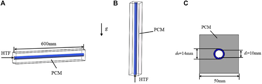
FIGURE 1. Shell-and-tube phase-change heat storage unit: (A) horizontal placement, (B) vertical placement and (C) cross-section of the unit.
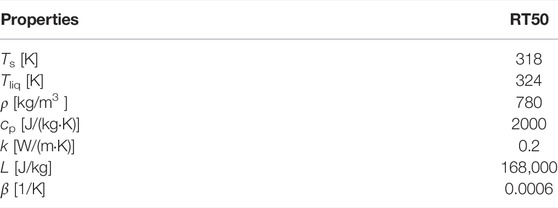
TABLE 1. Thermophysical properties of RT50 (Hosseini et al., 2012).
Besides, the dynamic viscosity of RT50 was considered temperature-dependent, and the relationship between dynamic viscosity and temperature can be expressed as:
where A and B are both constant, and were respectively set to 0.819 and -0.01546 (Hosseini et al., 2012).
For organic phase change materials, the thermal conductivity is usually small, which is also one of the shortcomings in LHTES applications. A common solution is to use finned tubes to enhance the heat transfer. Some studies investigated the effects of fin height as well as its spacing on heat transfer enhancement, and some researchers have already designed various fin structures to improve the heat transfer efficiency. However, most of the new fin structures are complicated and difficult to widely used. The present study adopted the two common fin structures, straight fins and annular fins, and investigated their influence on the PCM melting process. For better comparison, the same surface area and the volume were designed for both types of fins. Figure 2 and Figure 3 depict the straight-fin-tube and annular-fin-tube heat storage unit, in which the fins were installed on the horizontal heat storage tube as shown in Figure 1A. It can be seen from the cross-sectional view in Figures 2, 3, the height is 9 mm and the thickness is 2 mm for both types of fins. There are 33 annular fins with the spacing of 17 mm installed on the outer of the tube. The material for both tubes and fins is 304 stainless steel, and its thermal conductivity and density were set to be 16.2 W m−1·K−1 and 7,930 kg m−3, respectively.
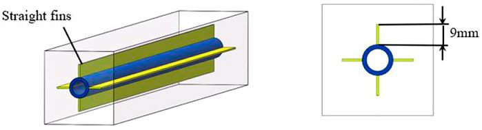
FIGURE 2. The shape and dimensions of the straight-fin-tube heat storage unit.
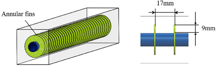
FIGURE 3. The shape and dimensions of the annular-fin-tube heat storage unit.
Numerical Model
In order to simplify the numerical model, the following hypotheses were proposed: 1) The shell side of the heat storage unit was regarded as adiabatic due to the good thermal insulation. 2) The natural convection was considered during the melting of PCM. As mentioned by some studies (Sarı and Kaygusuz, 2002; Dhaidan et al., 2013; Yazici et al., 2014), the convective heat transfer cannot be neglected during the phase-change heat storage process. 3) Both the water and PCM have uniform and isotropic thermophysical properties. 4) The thickness of the tube and the fin was also considered in this paper.
For the solution of the phase-change process, the enthalpy-porosity method (Brent et al., 1988; Gong et al., 1999) has been widely used, and the phase interface can be determined by solving the enthalpy distribution. The governing equations include continuity equation, momentum equation and energy equation as below.
Continuity equation:
Momentum equation:
Energy equation:
where hsens is the sensible enthalpy, which can be expressed as:
And the latent enthalpy hlat can be written as follows:
where L is the latent heat of the material, and λ can be definned as:
In Eq. 3, the source term
Amush is mushy zone constant, which is usually taken between 104–107. In the present study, it was set to 106. Besides, the constant
Boundary and Initial Conditions
The initial temperature of the PCM T0 was set to 25°C, and the inlet temperature Tf,i and velocity v of the HTF are respectively 70°C and 0.044 m/s. In addition, the outer surface of the shell side was assumed to be insulated.
Computational Methodology and Validation
The governing equations were solved by the commercial CFD code ANSYS Fluent 19.2. The Semi-Implicit Pressure-Linked Equation (SIMPLE) algorithm (Patankar, 2018) was employed to solve the pressure-velocity coupling equations, and the PRESTO scheme was adopted for the pressure correction equation. Besides, the number of mesh grids and time step independence validations were also performed. As illustrated in Figure 4, the numerical results have an acceptable accuracy as the number of mesh grids exceeds 272,000 and the time step is lower than 0.2 s. Therefore, the grid number of 272,000 and the time step of 0.2 s were used in the present simulation in order to reduce the computational cost. In addition, the residual errors were set to 10−6 for the energy equation and 10–5 for other variables.
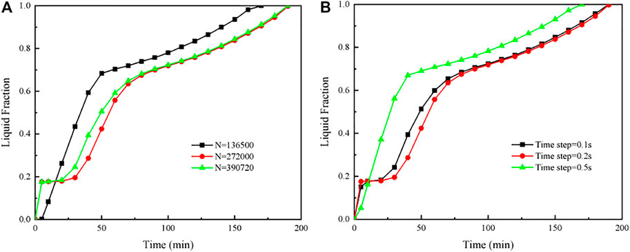
FIGURE 4. Independence validations on (A) grid number and (B) time step.
In order to validate the numerical model established in the present study, the average temperature profile in the PCM was compared with the experimental results obtained from Hosseini et al. (Hosseini et al., 2012). As shown in Figure 5, good agreement can be observed, and the temperature deviation is within 5%.
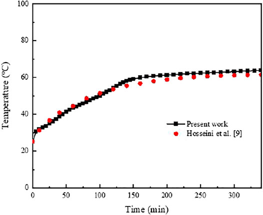
FIGURE 5. Comparison of the average temperature profile in the PCM obtained from the present numerical model against the experimental results from Hosseini et al. (Hosseini et al., 2012).
Results and Discussion
Effects of the Heat Storage Unit Placement Forms on the Phase-Change Process
The effects of the unit placement forms on the phase-change process were investigated. Figure 6 depicts the variation trends of liquid fraction versus time for the vertical and horizontal heat storage units at different tube diameters. It can be found that the vertical heat storage unit has a higher melting rate than the horizontal one when the tube diameter is larger. However, the opposite results were obtained at the smaller tube diameter as shown in Figure 6B. In terms of melting time, the phase change process in the vertical heat storage unit was greatly affected by the tube diameter (i.e. the thickness of the PCM). Besides, compared with the vertical heat storage unit, the PCM melting process is more complicated in the horizontal one, which can be divided into three stages according to the dominant heat transfer: the conduction-led stage in the initial period, the convection-led stage in the intermediate period and the conduction-led stage in the final period. Figure 7 shows the profiles of velocity and liquid fraction on the middle cross-section of the horizontal heat storage unit. Combined with Figure 6A, the three stages during the PCM melting process can be further analyzed.
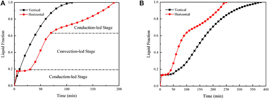
FIGURE 6. Variations of liquid fraction versus time for the vertical and horizontal heat storage units. (A) do = 14 mm, di = 10 mm. (B) do = 10 mm, di = 6 mm.
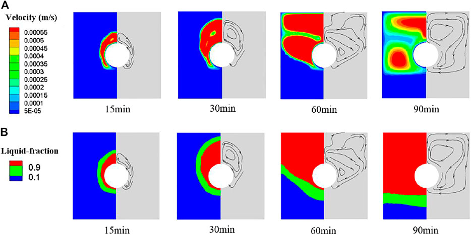
FIGURE 7. Profiles of the velocity and liquid fraction on the middle cross-section along the length of the horizontal heat storage unit during the PCM melting process. (A) Velocity profiles. (B) Liquid fraction profiles. The black arrows indicate the flow direction of the liquid PCM. The outer/inner diameter (do/di) of the tube is 14/10 mm.
In the initial stage, the thin layer of PCM which directly contacts with the tube wall is heated and rapidly melts due to the heat conduction. And then, the heat conduction is worsened because of the increased thermal resistance as the thickness of the liquid PCM increases. At this moment, the variation of liquid fraction tends to be flattened as depicted in Figure 6A. As the liquid region gradually expands, the natural convection occurs driven by the density differences. It can be observed from Figure 7, the liquid PCM climbs up along the hot tube wall and descends along the cold solid-liquid interface, forming a natural convection cycle. Thus, the melting rate of RT50 significantly increases in this intermediate stage. After 60 min, the solid-liquid interface drops to the lower part of the shell side, and the PCM in the upper part completely melts. As the solid-liquid interface shrinks, the natural convection is weakened, leading to the reduction of melting rate. In the final stage, the heat conduction dominants again due to the thinning of the solid PCM.
Effects of Finned Tubes on the Phase-Change Process of PCM
To investigate the enhancement of PCM melting process by adopting finned tubes, the straight-fin tube and the annular-fin tube were compared in the horizontal heat storage units. It can be seen from Figure 8, compared with the finless tube, the melting time of PCM is shortened by 31.6% with the annular-fin tube and 42.1% by using the straight-fin tube. Obviously, the reinforced heat transfer by the straight-fin tube is much better. By analyzing the velocity and liquid fraction profiles as illustrated in Figure 9, it can be found that the PCM flow region is significantly enlarged for a very short time by adopting the straight-fin tube at the beginning of the melting process, basically covering the entire unit. Therefore, the total melting time of PCM is reduced, which is mainly determined by the convection-led stage, since the natural convection is greatly enhanced.
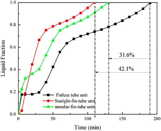
FIGURE 8. Variations of liquid fraction versus time for the horizontal heat storage units with the finless tube, straight-fin tube and annular-fin tube. The outer/inner diameter (do/di) of the tube is 14/10 mm.
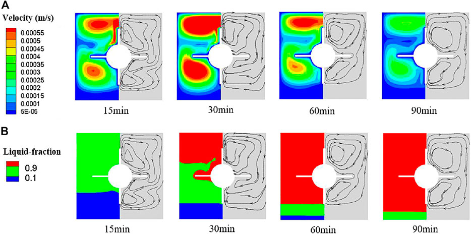
FIGURE 9. Profiles of the velocity and liquid fraction on the middle cross-section along the length of the horizontal heat storage unit with the straight-fin tube during the PCM melting process. (A) Velocity profiles. (B) Liquid fraction profiles.
In order to better observe the phase change process in the annular-fin-tube heat storage unit, four typical cross-sections at 0 mm, 3 mm, 6 mm and 9 mm away from the middle fin were selected as indicated in Figure 10 based on the left-right symmetry of the heat storage unit. Cross-section D is almost located at the middle of the two adjacent annular fins, and cross-section A is located on the surface of the middle fin. At the moment of 15 min, the velocity and liquid fraction profiles on the selected cross-sections were displayed in Figure 11. As can be found that there are no streamlines on the cross section A. The liquid region on cross section B is the largest, and gradually shrinks as the distance from the middle fin increases due to the weaken of heat conduction. During the melting process, the profiles of velocity and liquid fraction on cross section B were also drawn in Figure 12. Both the flow fields and liquid fraction are quite similar to those in the finless tube heat storage unit as shown in Figure 7. Since the convective region is not significantly expanded by the annular fins, the enhancement of convective heat transfer is limited. Therefore, the reduction of PCM melting time due to the annular fins is mainly attributed to the heat conduction intensifying in the initial period as can be clearly seen from Figure 8.
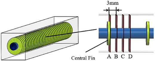
FIGURE 10. Schematic of four selected typical cross-section positions of the annular-fin-tube heat storage unit.
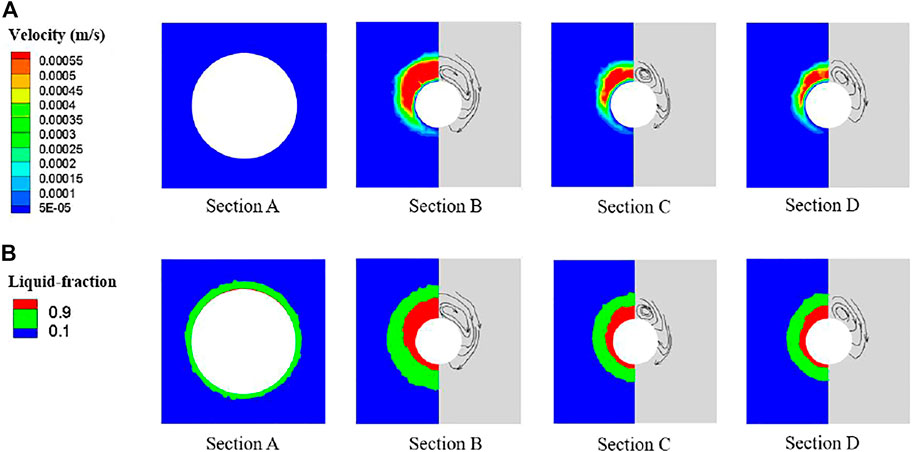
FIGURE 11. Profiles of the velocity and liquid fraction on the four selected cross-sections of the annular-fin-tube horizontal heat storage unit at the moment of 15 min. (A) Velocity profiles. (B) Liquid fraction profiles.
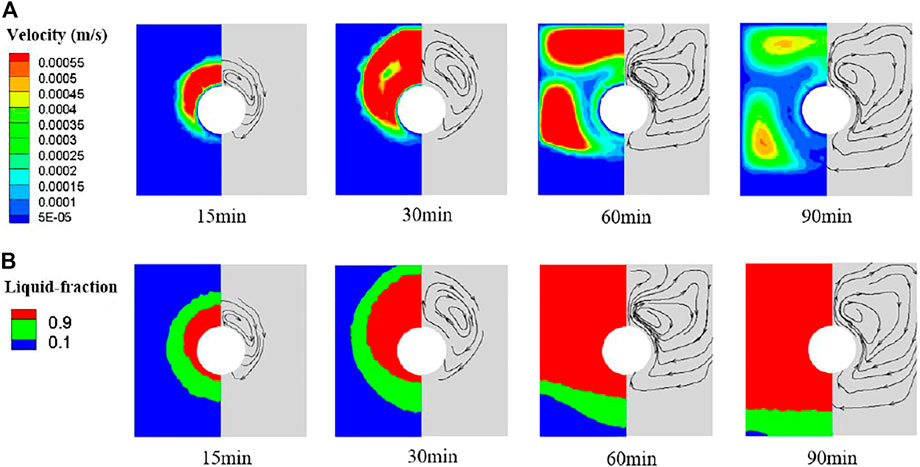
FIGURE 12. Profiles of the velocity and liquid fraction on cross-section B of the annular-fin-tube horizontal heat storage unit during the PCM melting process. (A) Velocity profiles. (B) Liquid fraction profiles.
In order to verify the numerical simulation results obtained from the present numerical model, the experimental studies on the melting process of Paraffin wax RT50 in the straight-fin-tube and annular-fin-tube heat storage units were respectively performed. Note that Paraffin wax RT50 is white in the solid state and colorless in the liquid state. Compare Figures 13A,B, it can be found that the melting rate of RT50 by using the straight-fin tube is higher than that with the annular-fin tube, which is consistent with the numerical results as mentioned above. Since the melting process has obviously stepped into the conduction-led stage in the final period after 120 min, the melting rate of RT50 becomes slowly in this stage due to its low thermal conductivity. Thus, the melting process on the cross-section was not involved in Figure 13 after 120 min. Besides, the complete melting time of RT50 in the experiments is a little longer than that in the numerical simulations owing to the poor insulation measures. In addition, more experimental studies will be carried out in the future work.
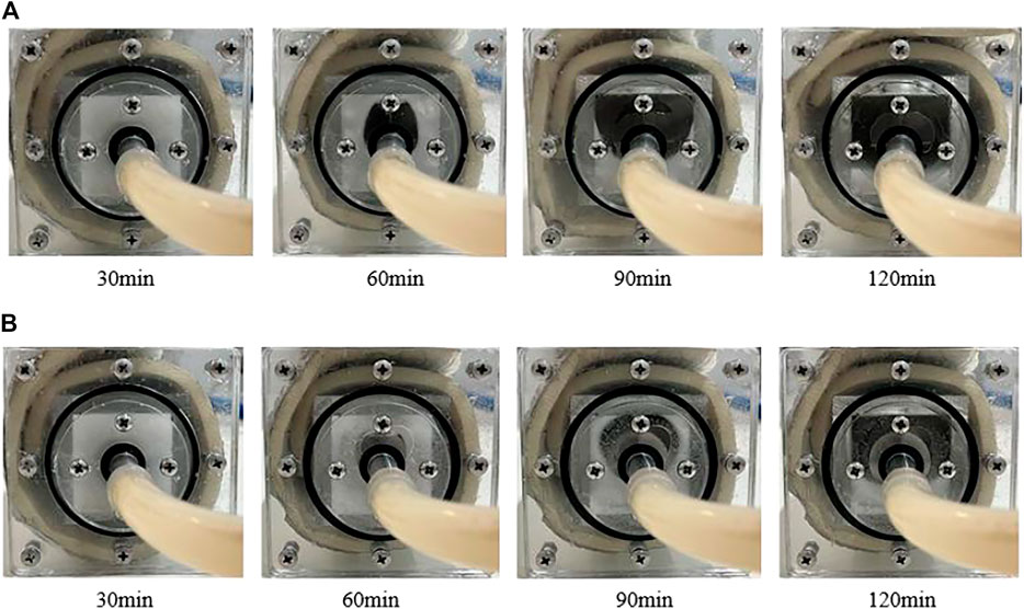
FIGURE 13. Melting process of Paraffin wax RT50 in the finned tube heat storage units. (A) Straight-fin-tube heat storage unit. (B) Annular-fin-tube heat storage unit.
Mechanism of Natural Convective Heat Transfer in the Finned Tube Heat Storage Units
The natural convection can be simplified in the finned tube heat storage units as shown in Figure 14. As for the straight-fin-tube heat storage unit depicted in Figures 14A, a relatively closed space is formed by the hot tube and straight fins as well as the cold shell. In this space, the liquid PCM climbs up along the hot wall and descends down along the cold wall, forming a natural convective cycle. In the case of the annular-fin-tube heat storage unit drawn in Figure 14B, the natural convective cycle cannot be formed by the temperature difference, since the annular fins are parallel to each other. In this situation, the flow rises along the hot wall, and is forced to change its direction when it encounters the upper cold shell, which is similar to the flow in the finless tube unit. Thus, the annular-fin tube cannot effectively enhance the convective heat transfer in the PCM melting process.
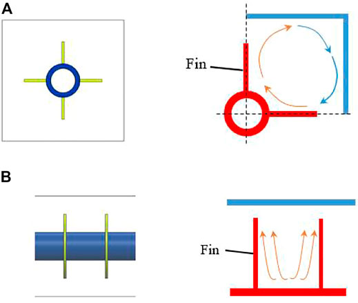
FIGURE 14. Schematic of natural convective heat transfer in the finned tube heat storage units. (A) Straight-fin-tube heat storage unit. (B) Annular-fin-tube heat storage unit.
As is well-known, the thermal conductivity of paraffin wax often used as PCM in LHTES is very small, and the application of fins has a limited effect on heat conduction enhancement. Therefore, the enhancement of natural convection heat transfer by fins should be carefully considered. Two suggestions on the design of the finned tube applied in the phase change heat storage unit were finally proposed in this paper. 1) The hot finned tube wall and the cold shell should be arranged vertically facing each other in the closed space to form a natural convective cycle. 2) The temperature gradient in the hot wall and the cold wall should be designed vertically upwards, as indicated in Figure 15, in order to enhance the natural convection.

FIGURE 15. Schematic of natural convective cycle and wall temperature gradients.
Conclusion
In this paper, a numerical model was established by using the enthalpy-porosity approach to study the melting behavior of Paraffin wax RT50 in a heat storage unit belonging to a shell-and-tube heat exchanger. The effects of heat storage unit placement forms, tube diameters and fin structures on the phase change process of RT50 were investigated, and the heat transfer characteristics during different melting periods were deeply analyzed. Besides, the mechanism of heat transfer enhancement due to fins and the fin design suggestions in the heat storage unit were also proposed. The main conclusions are drawn as follows:
1) The phase-change process in the vertical heat storage unit was greatly affected by the tube diameter (i.e. the thickness of PCM). For the heat storage unit in horizontal arrangement, the melting process of RT50 can be divided into three stages in terms of dominant heat transfer: the conduction-led stage in the initial period, the convection-led stage in the intermediate period and the conduction-led stage in the final period. In addition, the melting time (or melting rate) of RT50 was mainly determined by the convection-led stage.
2) For heat transfer enhancement, the straight and annular fins were installed on the outer of the tube in the horizontal heat storage unit. Compared with the finless tube, the complete melting time of RT50 was shortened by 42.1% and 31.6% respectively for the straight-fin tube and the annular-fin tube. Thus, adopting the straight fins is a better option to improve the phase change process for the present heat storage unit.
3) The mechanism of heat transfer enhancement by fins was also analyzed. For the straight-fin-tube heat storage unit, the natural convective heat transfer was significantly intensified during the melting process of RT50. By using the annular fins, the conduction in the initial melting period was improved, but the annular fins have limited effect on enhancing the natural convection.
4) The suggestions on the fin design applied to the present heat storage unit were given. To improve the natural convection, the hot fin tube wall and the cold shell should be arranged vertically facing each other to form a relatively closed space, where the natural convective cycle is more likely to occur. Besides, the temperature gradients both in the hot wall and cold wall should be vertical upwards.
Data Availability Statement
The raw data supporting the conclusion of this article will be made available by the authors, without undue reservation.
Author Contributions
JF is responsible for guiding experimental and numerical simulation work, guiding the revision of papers, and providing funds for research; TH is responsible for planning and completing numerical simulation and experimental work, processing data, writing the first draft and revision of articles, etc.; YB is responsible for guiding article revision, HY is responsible for assisting experiments, and JW is responsible for providing research process guidance and financial support.
Funding
The present work is supported by Funds of International Cooperation and Exchange of the National Natural Science Foundation of China (Research collaboration NSFC-VR) (No. 51961135102).
Conflict of Interest
The authors declare that the research was conducted in the absence of any commercial or financial relationships that could be construed as a potential conflict of interest.
Publisher’s Note
All claims expressed in this article are solely those of the authors and do not necessarily represent those of their affiliated organizations, or those of the publisher, the editors and the reviewers. Any product that may be evaluated in this article, or claim that may be made by its manufacturer, is not guaranteed or endorsed by the publisher.
References
Agyenim, F., Hewitt, N., Eames, P., and Smyth, M. (2010). A Review of Materials, Heat Transfer and Phase Change Problem Formulation for Latent Heat thermal Energy Storage Systems (LHTESS). Renew. Sust. Energ. Rev. 14, 615–628. doi:10.1016/j.rser.2009.10.015
Alkaabi, A. K., Addad, Y., and Alameri, S. A. (2019). “Hydro-thermal Assessment Around Triangularly Positioned PCM Containers in a Hybrid TES-Nuclear Power Plant System,” in Proceedings of 2019 International Congress on Advances in Nuclear Power Plants (ICAPP'19), Juan-les-pins, France, May 2019.
Allen, M. J., Sharifi, N., Faghri, A., and Bergman, T. L. (2015). Effect of Inclination Angle during Melting and Solidification of a Phase Change Material Using a Combined Heat Pipe-Metal Foam or Foil Configuration. Int. J. Heat Mass Transfer 80, 767–780. doi:10.1016/j.ijheatmasstransfer.2014.09.071
Blen, K., Takgil, F., and Kaygusuz, K. (2008). Thermal Energy Storage Behavior of CaCl2.6H2O during Melting and Solidification. Energy Sourc. A: Recovery, Utilization, Environ. Effects 30, 775–787. doi:10.1080/15567030601082175
Brent, A. D., Voller, V. R., and Reid, K. J. (1988). Enthalpy-Porosity Technique for Modeling Convection-Diffusion Phase Change: Application to the Melting of a Pure Metal. Numer. Heat Transfer 13, 297–318. doi:10.1080/10407788808913615
Dhaidan, N. S., Khodadadi, J. M., Al-Hattab, T. A., and Al-Mashat, S. M. (2013). Experimental and Numerical Investigation of Melting of Phase Change Material/nanoparticle Suspensions in a Square Container Subjected to a Constant Heat Flux. Int. J. Heat Mass Transfer 66, 672–683. doi:10.1016/j.ijheatmasstransfer.2013.06.057
Dutil, Y., Rousse, D. R., Salah, N. B., Lassue, S., and Zalewski, L. (2011). A Review on Phase-Change Materials: Mathematical Modeling and Simulations. Renew. Sust. Energ. Rev. 15, 112–130. doi:10.1016/j.rser.2010.06.011
Ghahremannezhad, A., Xu, H., Salimpour, M. R., Wang, P., and Vafai, K. (2020). Thermal Performance Analysis of Phase Change Materials (PCMs) Embedded in Gradient Porous Metal Foams. Appl. Therm. Eng. 179. doi:10.1016/j.applthermaleng.2020.115731
Ghalambaz, M., Mehryan, S. A. M., Veismoradi, A., Mahdavi, M., Zahmatkesh, I., Kazemi, Z., et al. (2021). Melting Process of the Nano-Enhanced Phase Change Material (NePCM) in an Optimized Design of Shell and Tube thermal Energy Storage (TES): Taguchi Optimization Approach. Appl. Therm. Eng. 193, 116945. doi:10.1016/j.applthermaleng.2021.116945
Gharebaghi, M., and Sezai, I. (2007). Enhancement of Heat Transfer in Latent Heat Storage Modules with Internal Fins. Numer. Heat Transfer, A: Appl. 53, 749–765. doi:10.1080/10407780701715786
Gong, Z.-X., Devahastin, S., and Mujumdar, A. S. (1999). Enhanced Heat Transfer in Free Convection-Dominated Melting in a Rectangular Cavity with an Isothermal Vertical wall. Appl. Therm. Eng. 19, 1237–1251. doi:10.1016/s1359-4311(99)00003-4
Guo, C., and Zhang, W. (2008). Numerical Simulation and Parametric Study on New Type of High Temperature Latent Heat thermal Energy Storage System. Energ. Convers. Manag. 49, 919–927. doi:10.1016/j.enconman.2007.10.025
Guo, X., and Goumba, A. P. (2018). Process Intensification Principles Applied to Thermal Energy Storage Systems—A Brief Review. Front. Energ. Res. 6, 17. doi:10.3389/fenrg.2018.00017
Hosseini, M. J., Ranjbar, A. A., Sedighi, K., and Rahimi, M. (2012). A Combined Experimental and Computational Study on the Melting Behavior of a Medium Temperature Phase Change Storage Material inside Shell and Tube Heat Exchanger. Int. Commun. Heat Mass Transfer 39, 1416–1424. doi:10.1016/j.icheatmasstransfer.2012.07.028
Ibrahem, A. M., El-Amin, M. F., and Sun, S. (2017). Effects of Nanoparticles on Melting Process with Phase-Change Using the Lattice Boltzmann Method. Results Phys. 7, 1676–1682. doi:10.1016/j.rinp.2017.04.032
Lacroix, M. (1993). Numerical Simulation of a Shell-And-Tube Latent Heat thermal Energy Storage Unit. Solar energy 50, 357–367. doi:10.1016/0038-092x(93)90029-n
Lamberg, P., Lehtiniemi, R., and Henell, A.-M. (2004). Numerical and Experimental Investigation of Melting and Freezing Processes in Phase Change Material Storage. Int. J. Therm. Sci. 43, 277–287. doi:10.1016/j.ijthermalsci.2003.07.001
Meghari, Z., Bouhal, T., Benghoulam, M., Rhafiki, T. E., Khattabi, E. M. E., doghmi, H., et al. (2021). Numerical Simulation of a Phase Change Material in a Spherical Capsule with a Hollow Fin. J. Energ. Storage 43, 103024. doi:10.1016/j.est.2021.103024
Nemati, H., and Habibi, M. (2021). Analytical and Numerical Analysis of Phase Change Material Solidification in Partially Filled Capsules Considering Breathing Vent. J. Energ. Storage 40, 102725. doi:10.1016/j.est.2021.102725
Norouzi, N., Fani, M., and Talebi, S. (2021). Exergetic Design and Analysis of a Nuclear SMR Reactor Tetrageneration (Combined Water, Heat, Power, and Chemicals) with Designed PCM Energy Storage and a CO2 Gas Turbine Inner Cycle. Nucl. Eng. Tech. 53, 677–687. doi:10.1016/j.net.2020.07.007
Pahamli, Y., Hosseini, M. J., Ranjbar, A. A., and Bahrampoury, R. (2016). Analysis of the Effect of Eccentricity and Operational Parameters in PCM-Filled Single-Pass Shell and Tube Heat Exchangers. Renew. Energ. 97, 344–357. doi:10.1016/j.renene.2016.05.090
Rathod, M. K., and Banerjee, J. (2015). Thermal Performance Enhancement of Shell and Tube Latent Heat Storage Unit Using Longitudinal Fins. Appl. Therm. Eng. 75, 1084–1092. doi:10.1016/j.applthermaleng.2014.10.074
Sarı, A., and Kaygusuz, K. (2002). Thermal and Heat Transfer Characteristics in a Latent Heat Storage System Using Lauric Acid. Energ. Convers. Manag. 43, 2493–2507. doi:10.1016/s0196-8904(01)00187-x
Sciacovelli, A., Gagliardi, F., and Verda, V. (2015). Maximization of Performance of a PCM Latent Heat Storage System with Innovative Fins. Appl. Energ. 137, 707–715. doi:10.1016/j.apenergy.2014.07.015
Sharma, A., Sharma, S. D., and Buddhi, D. (2002). Accelerated thermal Cycle Test of Acetamide, Stearic Acid and Paraffin Wax for Solar thermal Latent Heat Storage Applications. Energ. Convers. Manag. 43, 1923–1930. doi:10.1016/s0196-8904(01)00131-5
Shin, D. H., Park, J., Choi, S. H., Ko, H. S., Karng, S. W., and Shin, Y. (2019). A New Type of Heat Storage System Using the Motion of Phase Change Materials in an Elliptical-Shaped Capsule. Energ. Convers. Manag. 182, 508–519. doi:10.1016/j.enconman.2018.12.091
Viskanta, R. (2018). Phase-change Heat Transfer, Solar Heat Storage: Latent Heat Materials. Boca Raton: CRC Press, 153–222.
Yazici, M. Y., Avci, M., Aydin, O., and Akgun, M. (2014). On the Effect of Eccentricity of a Horizontal Tube-In-Shell Storage Unit on Solidification of a PCM. Appl. Therm. Eng. 64, 1–9. doi:10.1016/j.applthermaleng.2013.12.005
Yu, Q., Romagnoli, A., Al-Duri, B., Xie, D., Ding, Y., and Li, Y. (2018). Heat Storage Performance Analysis and Parameter Design for Encapsulated Phase Change Materials. Energ. Convers. Manag. 157, 619–630. doi:10.1016/j.enconman.2017.12.040
Zhang, C., Li, J., and Chen, Y. (2020). Improving the Energy Discharging Performance of a Latent Heat Storage (LHS) Unit Using Fractal-Tree-Shaped Fins. Appl. Energ. 259, 114102. doi:10.1016/j.apenergy.2019.114102
Zheng, Z.-J., Xu, Y., and Li, M.-J. (2018). Eccentricity Optimization of a Horizontal Shell-And-Tube Latent-Heat thermal Energy Storage Unit Based on Melting and Melting-Solidifying Performance. Appl. Energ. 220, 447–454. doi:10.1016/j.apenergy.2018.03.126
Nomenclature
cp specific heat capacity (J·kg−1·K−1)
d tube diameter (m)
g gravity (m·s−2)
h enthalpy (J·kg−1)
k thermal conductivity (W·m−1·K−1)
L latent heat (J·kg−1)
P pressure (Pa)
T temperature (K)
v velocity (m·s−1)
Greek symbol
β expansion coefficient (K−1)
λ liquid fraction
μ dynamic viscosity (Pa·s)
ρ density (kg·m−3)
Subscripts
i inner
lat latent
liq liquid
o outer
ref reference
s solidus
sens sensible
f,i fluid inlet
Keywords: phase change material, melting, fins, natural convection, heat storage
Citation: Fang J, Han T, Bi Y, Yan H and Wei J (2022) Numerical Study on Heat Transfer and Enhancement Mechanism in PCM-Filled Shell-and-Tube Heat Exchangers. Front. Energy Res. 10:885564. doi: 10.3389/fenrg.2022.885564
Received: 28 February 2022; Accepted: 10 March 2022;
Published: 01 April 2022.
Edited by:
Luteng Zhang, Chongqing University, ChinaReviewed by:
Naveed Ahmed, National University of Sciences and Technology (NUST), PakistanWei Wu, Northwest University, China
Hossain Nemati, Islamic Azad University, Iran
Copyright © 2022 Fang, Han, Bi, Yan and Wei. This is an open-access article distributed under the terms of the Creative Commons Attribution License (CC BY). The use, distribution or reproduction in other forums is permitted, provided the original author(s) and the copyright owner(s) are credited and that the original publication in this journal is cited, in accordance with accepted academic practice. No use, distribution or reproduction is permitted which does not comply with these terms.
*Correspondence: Jiabin Fang, amlhYmluZmFuZ0BtYWlsLnhqdHUuZWR1LmNu