 Xu Han
 Litong Zhang1
 Yidan Yuan
- 1Science and Technology on Thermostructural Composite Materials Laboratory, Northwestern Polytechnical University, Xi’an, China
- 2China Nuclear Power Engineering Co Ltd, Beijing, China
- 3Beijing Institute of Long March Aerospace Vehicles, Beijing, China
- 4Institute of Advanced Structure Technology, Beijing Institute of Technology, Beijing, China
China Nuclear Power Engineering, Northwestern Polytechnical University, and Beijing Institute of Technology have undertaken a joint research work with the goal of developing corium retention containers for use in an innovative light-water reactor core grouping catcher (CGC). In Serious Accidents (SAs), the corium will be retained in the C/SiC ceramic composite spherical shell container and thrown into the pool for passive cooling. In order to investigate the capability of the C/SiC ceramic composites to withstand the high temperature of 1800°C and the huge thermal shock at the initial stage of cooling, in this work, the high-temperature performance of these composites is studied. Furthermore, the compatibility of these composites with corium is investigated, and a retention container design prototype is proposed. The thermal conductivity, thermal expansion coefficient, high-temperature tensile strength, and thermal shock resistance of the candidate C/SiC specimens to be used in the manufacturing of the detention container are measured. The FactSage software package is used for the chemical compatibility study and product composition analysis of the composite SiC deposition layer and corium. The corrosion process of the SiC deposition layer of the composite material caused by corium is investigated through high-temperature corrosion tests and the electron microscopy analysis of the SiC specimen with the incorporation of CeO2. The results show that the C/SiC ceramic composite can meet the design criteria of the CGC corium retention container, and it is impossible to cause a carbon reaction disaster through the failure of the composite SiC deposition layer.
1 Introduction
China Nuclear Power Engineering, Northwestern Polytechnical University, and Beijing Institute of Technology have recently investigated the application of C/SiC ceramic composites in the design of the light-water reactor (LWR) core catcher. The goal of the project is to develop corium retention containers for use in an innovative LWR core grouping catcher (CGC) (Han et al., 2018). Due to its innovative scheme, the CGC can reduce the direct contact between corium and water, increase the heat transfer area for cooling, and considerably simplify the final disposal of SAs.
Owing to their unique high-temperature properties (Katoh et al., 2012; Zinkle et al., 2014; Angelici Avincola et al., 2015), small neutron absorption cross sections, high oxidation resistance, chemical inertness, high melting point, low irradiation growth, and stabilization in nuclear waste, SiC ceramic composites have attracted significant interest for various nuclear applications. For example, these composites have been used in accident tolerant fuel (ATF) cladding for a pressurized water reactor (PWR) (Qiu et al., 2020), a wrapper tube for a sodium-cooled fast reactor (Braun et al., 2021), and a SiC-coated fuel particle capsule for a PWR (Lippmann et al., 2001). Compared with C/SiC composites, SiC/SiC composites have the advantages of a small neutron absorption cross section, high thermal conductivity, unified interfacial materials, and high chemical stability. Therefore, SiC/SiC composites are more suitable for ATF applications. However, for serious accidents that are extremely unlikely to occur and for low requirements on the material irradiation performance, C/SiC composites are more suitable than SiC/SiC composites as their technology is more mature and economical. In this study, the high-temperature performance of C/SiC ceramic composites was investigated, and the compatibility of these composites with the core melt was studied. Our results demonstrate the application feasibility of C/SiC composites as the structural material for core melt retention containers.
2 Conceptual Design of the CGC
2.1 Typical Core Catcher Design
Since the concept of the core catcher was first put forward, many schemes have been proposed. The most important among these schemes is the in-vessel corium retention (IVR) combined with the passive cooling of the external vessel surface, such as the core catchers of the VVER-440&640, AP1000, and BWR-1000 reactors (Khabensky et al., 2009). Another important scheme is the ex-vessel corium retention (EVR). In the EVR approach, the molten core is released into the under-reactor cavity of a concrete pit filled with water. Two typical EVR core catchers have been fully developed: 1) a crucible-type catcher developed for Russian NPPs with a VVER-1000 reactor (Kolev, 2001; Kukhtevich et al., 2001) and 2) a core catcher with melt spreading developed for the European EPR reactor (Sidorov et al., 2001; Fischer, 2004). As shown in Table 1, regardless of whether the IVR or EVR schemes are considered with crucible or spreading catchers, the functions of the core catcher design can be divided into three levels: 1) “Basic functions”, which depend on the system targets; 2) “Complete functions”, which are used to solve the derivative problems introduced by the establishment of the system; 3) “Additional functions”, which are related to the mutual support with other systems. This table compares and analyzes the core catcher function settings of the WWER and EPR reactors.
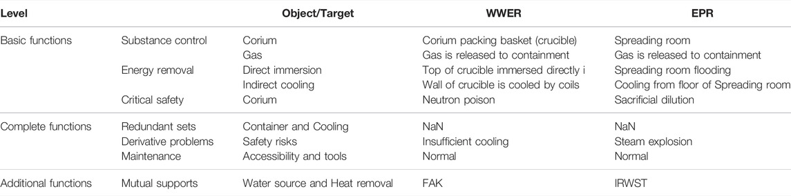
TABLE 1. Comparison of the functions of the WWER and EPR core catchers.
At the basic functional level, the corium mass is the most important factor in the core catcher design; the shape of the retention container, sacrificial material (SM) amount, neutron poison choice, and cooling mode depend on this factor. At the complete functional level, redundancy is not considered in the current design of the core catcher. Direct water contact for cooling introduces the risk of steam explosion. At an additional functional level, the cooling water required by the core catcher can be provided by other systems; this is an approach that meets the low-cost requirements of the core catcher design.
The current core catcher design does not take into account the final disposal of SAs. After the Fukushima nuclear accident, the melted core cannot be transferred, and has been continuously cooled for 10 years. Only the radioactive wastewater accumulated from unit 2 has reached almost one million cubic meters and is still being produced. Therefore, the future core catcher should have the following characteristics: 1) A good transportability to meet the final disposal requirements of the corium; 2) A high redundancy for the detention and cooling functions; 3) A good level of isolation to avoid the risk of steam explosion; 4) A high degree of compactness for minimizing the use of sacrificed materials and reducing the total amount of corium; 5) Passive features for a more reliable cooling.
2.2 CGC
In the innovative CGC scheme, corium will be retained in the C/SiC ceramic composite spherical shell container and thrown into the pool for passive cooling.
Figure 1 shows a schematic diagram of the CGC principle. After the reactor pressure vessel (RPV) failure, corium will undergo four processes, namely distribution, perfusion, transfer, and cooling, to achieve a long-term retention. The scheme of a compact CGC is shown in Figure 2. After the RPV failure, the molten core does not spread into the catcher immediately; corium will first flow into a premix chamber containing the SM of fusible oxides so that its temperature can be reduced to 1800°C. The presence of the SM and premix chamber ensures corium retention for a period exceeding the time of the melt relocation from the vessel. During this period, the decay heat of the corium and relocated molten core is exploited for the SM melting and dissolution. The SM can immobilize the corium in the premix chamber temporarily for around 1 h. The melt will then penetrate through the bottom plate (first Plate) of the premix chamber and flow into the perfusion chamber. Spherical corium retention containers were piled in the perfusion chamber, and the gaps between the containers were filled with the SM. The diameter of the retention containers is larger in the upper region of the perfusion chamber and decreases toward the bottom region. The SM in the perfusion chamber can protect the surface of the retention containers and increase the fluidity of corium. As shown in Figures 3, 4, the corium retention container consists of a ceramic shell and an inner metal bladder. When the metal bladder is prevacuumized melted, corium will be transferred into the retention container. Similar to the process in the premix chamber, corium will be immobilized in the perfusion chamber for a sufficient amount of time to complete the perfusion process and cool down further. The containers and residual melt will then penetrate through the bottom plate (second Plate) of the perfusion chamber and pour into the lubrication chamber. The SM in the lubrication chamber serves a lubricant. After a short stagnation period, the containers and residual corium will melt through the bottom of the lubrication chamber (Final Plate) and fall into the main cooling pool.
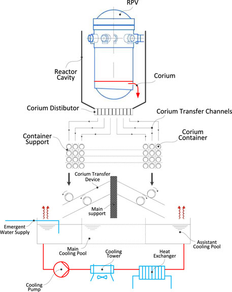
FIGURE 1. Schematic diagram of the CGC principle.
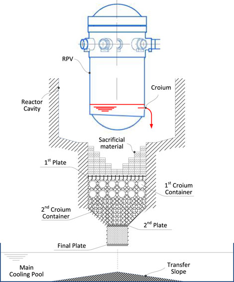
FIGURE 2. Scheme of the compact CGC.
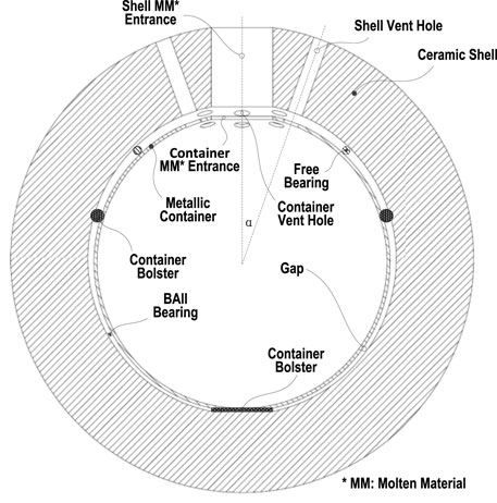
FIGURE 3. Corium retention container (Open Bladder).
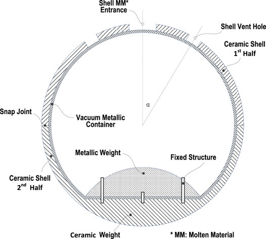
FIGURE 4. Corium retention container (Vacuum Bladder).
The most important aspects of the core grouping catcher are the designs of the corium retention container and functional SM. In this work, the high-temperature performance of the C/SiC ceramic composites was investigated, and their compatibility with the core melt was studied. Our findings prove the application feasibility of C/SiC composites as the structural material for core melt retention containers.
3 Thermal Shock Properties of the C/SiC Composites
The thermal shock resistance of the C/SiC composites is an important parameter that should be considered for their application in the detention container. As the temperature of corium is in the range of 1800–2000°C, the thermal shock properties of the C/SiC composites were investigated in a simulated process as follows: the C/SiC composites were heated using an oxyacetylene flame for 30 s to stabilize the temperature, which was measured to be 1850–2000°C using an infrared thermometer. The flame temperature was controlled by adjusting the ratio of oxygen gas to acetylene gas. The heated C/SiC composites were then dropped in distilled water to cool down within seconds. The tensile strengths of the thermally shocked C/SiC composites were measured and compared with those of the as-received samples. The results are presented in Table 2.
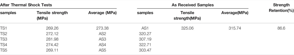
TABLE 2. Tensile strengths of the C/SiC composites before and after the thermal shock tests.
The damage caused to the C/SiC composites during the thermal shock process is due to the two following reasons. One cause of damage is the high-temperature flame, which damages the fiber and matrix through oxidation and consequently affects the tensile strength of the composites. This type of damage should also occur when corium fills the C/SiC containers in real application environments. The second cause of damage is the internal stress that is induced due to the rapid temperature change from 1800°C to 2000°C to room temperature. Owing to the difference in the coefficients of thermal expansion (CTEs) between the SiC matrix and the carbon fiber, SiC experiences a compressive stress at high temperatures followed by a tensile stress at room temperature, which results in cracks in the matrix and a reduction in the strength of the composites. After the thermal shock, the C/SiC composites still retained 86.6% of their original strength, which satisfies the strength requirement for the corium container. The weak interface in the C/SiC composites is beneficial to deflect the propagation of cracks in the matrix, which contributes to partially release the internal stress, thus leading to the high strength retention observed during the thermal shock.
4 Corrosion of SiC due to Corium
The main components of corium are listed in Table 3.
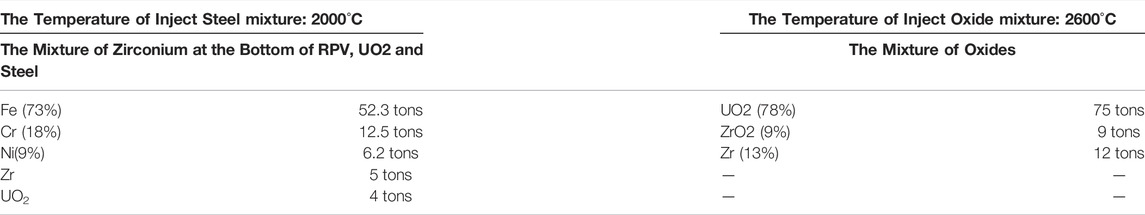
TABLE 3. Main components of corium.
As the spherical C/SiC container has an inner radius of 100 mm with 0.1-mm-thick SiC coatings, the molar ratios of SiC to the elements in the mixture composed of RPV material, UO2, and steel should be SiC:Fe:Cr:Ni:Zr:UO2 = 0.25:47.98:12.33:5.44:2.81:0.75. Under the same assumptions, the ratios of SiC to the elements in the molten oxide mixture should be SiC:UO2:ZrO2:Zr = 0.25:14.24:3.75:6.75.
4.1 Thermodynamic Analysis of the Corrosion of SiC due to Corium
Based on the aforementioned ratios of SiC to the molten oxide mixture and of SiC to the mixture of RPV, UO2, and steel, the reaction products can be calculated using the FactSage software package. It is noted that, due to the reactions of SiC with the molten oxide mixture and the mixture of RPV, UO2, and steel, the newly formed condensed phases are ZrC and SiZr2 in the temperature range of 1800–2500°C and ZrC and Si 3Zr5 at 2600°C. The other condensed phases are not involved in the reactions. The gaseous products are summarized and depicted in Figure 5.
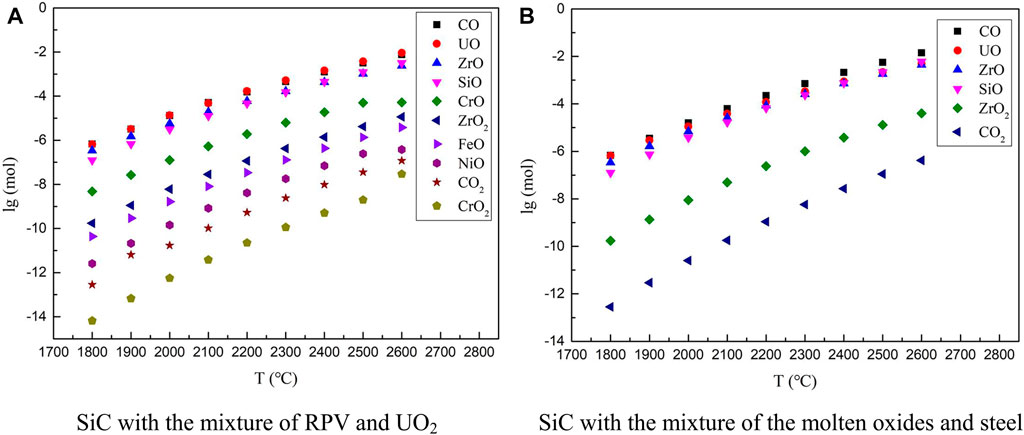
FIGURE 5. Gaseous products in the reactions of SiC with corium.
According to the Calculation Results, the Possible Reactions Between SiC and Corium Are Listed Below
As can be seen from Figure 6, the concentrations of all the gaseous products increase with the increase in the reaction temperature. This indicates that all the metals and oxides can corrode the SiC coatings at high temperatures. However, the concentration of all the gaseous products is low, indicating that this high-temperature corrosion of SiC due to corium is not pronounced. The concentration of hazardous gas, such as explosive CO, is too low to be omitted. A lower concentration of gaseous products is obtained for the reaction between SiC and the mixture of the oxide melt compared with that obtained for the reaction between SiC and the mixture of RPV, UO2, and steel; this indicates that the oxide melt causes less corrosion to the SiC coating.
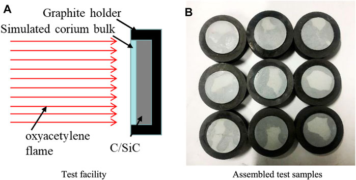
FIGURE 6. Schematic assembly of the corium and C/SiC composites for the kinetic corrosion test.
The above results were obtained based on the assumption that all the SiC coatings would fully react with corium. In a real situation, corium only corrodes the SiC coatings on the contacted interfaces. The formation of ZrC and Si2Zr (or Si3Zr5 at 2600°C) during the corrosion at the interface would hinder the further corrosion of SiC. Therefore, the corrosion of the C/SiC container due to corium is limited, and the concentration of the generated gaseous products is suitable from a safety perspective.
4.2 Kinetics of the Corrosion of C/SiC due to Corium
The kinetics of two types of corium (listed in Table 3) were studied in the temperature range of 1,400–2000°C. In nuclear material research, CeO2 is often used as a surrogate for UO2 for its similar physical and chemical properties (Patnaik et al., 2021). So UO2 oxide was replaced with the simulated CeO2. A high-temperature oxyacetylene flame was achieved by adjusting the ratio between acetylene gas and oxygen gas. The bulk with a corium ratio as shown in Figure 6 (with UO2 substituted by CeO2) was pasted on the surface of the C/SiC composites. The oxyacetylene flame was oriented perpendicular to the surface of the composites. The schematic of the process is shown in Figure 6.
At each corrosion temperature, the reaction was allowed to proceed for three different durations, namely 150, 300, and 450 s. After the corrosion test, the cross sections of the corroded samples were observed via scanning electron microscopy (SEM), and the corrosion thickness was measured by comparing the corroded central area and the unreacted area at the rim of the C/SiC composites. A typical cross-sectional morphology image of the corroded samples is shown in Figure 7.
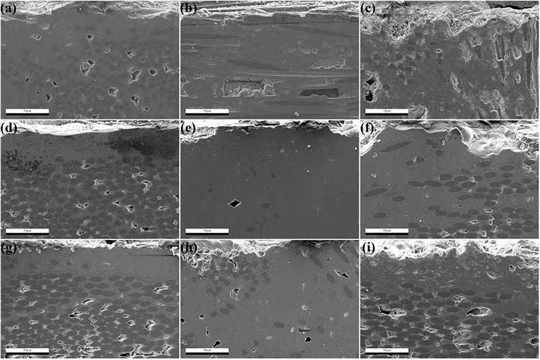
FIGURE 7. Typical cross-sectional morphology image of the corroded C/SiC samples.
As for the oxide corium, the corrosion temperatures measured using the infrared pyrometer were 1,400°C, 1,600°C, and 1900°C. The corresponding corrosion rates were found to be 0.0015, 0.004, and 0.012 μm/s, respectively.
Usually, a thermally activated reaction process obeys the Arrhenius equation, which is written as:
where CR is the corrosion rate, A is a constant, E is the activation energy for the corium corrosion, T is the temperature, and R is the universal gas constant.
By taking the logarithm of both sides of Eq. 9, the following equation is obtained:
The logarithm of the corrosion rates of SiC due to oxide corium as a function of the reciprocal of the temperature is plotted in Figure 8. The data is well fitted by a straight line, and the corrosion activation energy was calculated to be 126 kJ/mol from the slope of this line based on Eq. 10. The value of A was calculated to be 2.11 × 10⁻⁷.
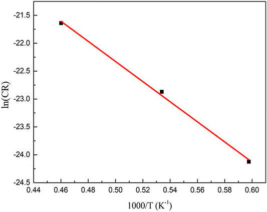
FIGURE 8. Logarithm of the corrosion rates of SiC due to oxide corium.
By substituting the values of E and A into Eq. 9, the corrosion rates at various temperatures can be predicted; the obtained results are listed in Table 4.
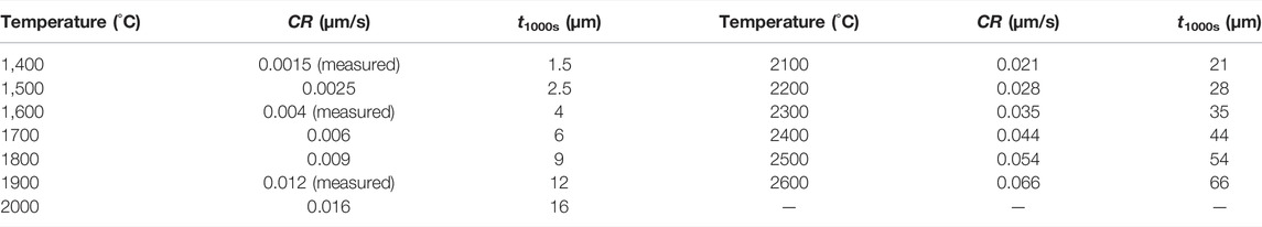
TABLE 4. Predicted corrosion rates of SiC due to oxide corium in the temperature range of 1,400–2600°C.
Based on the thermodynamic results and corrosion kinetics, the corrosion of SiC due to oxide corium is limited. Even at a temperature as high as 2600°C, the SiC thickness (t) that is corroded within 1,000 s is only 66 μm, which is less than the thickness of the C/SiC coatings. Although, according to the thermodynamic analysis, CO and SiO gases are produced during the corrosion, the kinetic results indicate that the corrosion reactions occur only on the contact areas. The amount of the gaseous products is less than 0.01 mol, and they can thus be omitted.
The corrosion kinetics of SiC due to the mixture of RPV, UO2, and steel was also studied. The measured corrosion temperatures were adjusted to 1,400°C, 1,600°C, and 1900°C. The corresponding corrosion rates were 0.002, 0.007, and 0.024 μm/s, respectively. The corrosion rates were measured using the aforementioned method for the corrosion of SiC due oxide corium. The corrosion rates and corresponding temperatures are plotted in Figure 9 according to Eq. 10
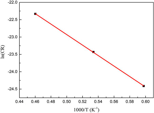
FIGURE 9. Logarithm of the corrosion rates of SiC due to the mixture of UO2 and steel. The data is fitted by a straight line. The corrosion activation energy and the value of A were calculated to be 150 kJ/mol and 1.66 × 10⁻⁶, respectively.
By substituting the values of E and A into Eq. 9, the corrosion rates of SiC due to the mixture of RPV, UO2, and steel in the temperature range of 1,400–2600°C can be predicted; the calculated results are listed in Table 5.
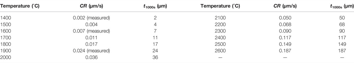
TABLE 5. Predicted corrosion rate of SiC due to the mixture of UO2 and steel in the temperature range of 1,400–2600°C.
Compared with the corrosion of SiC due to oxide corium, the corrosion of SiC due to the mixture of RPV, UO2, and steel is more significant. However, the molten mixture of RPV, UO2, and steel usually has a temperature lower than 2000°C in a real situation. Thus, the corroded thickness of SiC due to the melt at 2000°C within 1,000 s is only 36 μm, which is still less than the thickness of the C/SiC coatings.
5 Prototype Design of the Corium Retention Container
If the retention containers were filled with corium in case of an accident, they would be quickly dropped into water. The thermal shock resistance of the retention container material is an important parameter for real applications. Based on the results presented in Section 3, the C/SiC composite exhibits a good thermal shock resistance. The C/SiC composite retains a high strength after the thermal shock, which ensures that it can withstand the posttreatment, separation, and transportation processes after cooling.
The C/SiC composite has a thermal conductivity of 11–20 W/mK in the range from room temperature to 1800°C; thus, it can continuously conduct the corium internal heat to the cooling medium. However, the thermal conductivity of the C/SiC composite is still lower than that of most metals. Thus, the thickness of the C/SiC container should be appropriately reduced to be within 3 mm, which can effectively promote the heat transfer. In addition, the size of the C/SiC container can be reduced in order to effectively increase the heat transfer area. It is suggested that the diameter of the C/SiC spherical container should be ∼100 mm. This size would not only benefit the heat conduction but also reduce the costs related to the fabrication of C/SiC containers.
The failure of the C/SiC material caused by the corrosion due to corium at high temperatures is the most concerning issue. Through this study, it can be seen that C/SiC has a good corrosion resistance to corium at high temperatures. SiC usually only reacts with Zr in corium to form Zr2Si and ZrC condensed products, which can effectively prevent the further reaction between corium and SiC. The formation of CO from the reaction between carbide and the melt was initially thought to be an issue. However, the thermodynamic analysis and kinetic investigations show that the amount of CO formed in the system can be ignored. A large amount of C in the carbides is consumed by Zr to form stable ZrC, preventing the formation of CO.
SiC coatings play a key role in the application of C/SiC composites to detention containers. Crack-free and pore-free SiC coatings not only can ensure the thermochemical stability of the composite but are also beneficial to the mechanical and thermal conductivity of C/SiC. According to the kinetic results, a 100–150-μm-thick coating can meet the corrosion resistance requirements. This thickness is the most commonly adopted thickness for C/SiC composite coatings. It is recommended to add SiC whiskers or nanowires in the preparation process to improve the crack resistance of the SiC coating and avoid coating cracking during usage.
6 Conclusion
The results show that the C/SiC ceramic composite can meet the design criteria of the CGC corium retention container, and it is impossible to cause a carbon reaction disaster through the failure of the composite SiC deposition layer.
Data Availability Statement
The datasets presented in this article are not readily available because; The data came from a joint research. Requests to access the datasets should be directed to ZG9jLmhhbnh1QGdtYWlsLmNvbQ==.
Author Contributions
XH and JX conceived of the presented idea with some key advice from YY and WM. XH and LZ proposed the prototype design of the CGC. XH, HW, XZ and YW carried out the experiment. HW and XZ analyzed the raw experimental data and performed the calculation related.
Conflict of Interest
Authors XH, JX, WM, YY and XZ were employed by the company China Nuclear Power Engineering Co Ltd.
The remaining author declares that the research was conducted in the absence of any commercial or financial relationships that could be construed as a potential conflict of interest.
Publisher’s Note
All claims expressed in this article are solely those of the authors and do not necessarily represent those of their affiliated organizations, or those of the publisher, the editors and the reviewers. Any product that may be evaluated in this article, or claim that may be made by its manufacturer, is not guaranteed or endorsed by the publisher.
References
Angelici Avincola, V., Grosse, M., Stegmaier, U., Steinbrueck, M., and Seifert, H. J. (2015). Oxidation at High Temperatures in Steam Atmosphere and Quench of Silicon Carbide Composites for Nuclear Application. Nucl. Eng. Des. 295, 468–478. doi:10.1016/j.nucengdes.2015.10.002
Braun, J., Sauder, C., Rouillard, F., and Balbaud-Célérier, F. (2021). Mechanical Behavior of SiC/SiC Composites after Exposure in High Temperature Liquid Sodium for Sodium Fast Reactors Applications. J. Nucl. Mater. 546, 152743. doi:10.1016/j.jnucmat.2020.152743
Fischer, M. (2004). The Severe Accident Mitigation Concept and the Design Measures for Core Melt Retention of the European Pressurized Reactor (EPR). Nucl. Eng. Des. 230 (1), 169–180. doi:10.1016/j.nucengdes.2003.11.034
Han, X., Jing, C., Zhu, C., Wang, Y., Li, J., Yuan, Y., et al. (2018). Research on New Conceptual Design of PWR Core Catcher. J. Nucl. Power Eng. 39, 102–105. doi:10.13832/j.jnpe.2018.01.0102
Katoh, Y., Snead, L. L., Szlufarska, I., and Weber, W. J. (2012). Radiation Effects in SiC for Nuclear Structural Applications. Curr. Opin. Solid State. Mater. Sci. 16 (3), 143–152. doi:10.1016/j.cossms.2012.03.005
Khabensky, V. B., Granovsky, V. S., Bechta, S. V., and Gusarov, V. V. (2009). Severe Accident Management Concept of the VVER-1000 and the Justification of Corium Retention in a crucible-type Core Catcher. Nucl. Eng. Tech. 41 (5), 561–574. doi:10.5516/net.2009.41.5.561
Kolev, N. T. (2001). “SWR 1000 Severe Accident Control the Rough In-Vessel Melt Retention by External Cooling,” in Proc. of ICONE9, 9th Int. Conf. on Nucl. Eng, April 2-12, 2001, Nice, France (Nice, France: Framatome Advanced Nuclear Power, NDS1), 8–12.
Kukhtevich, I. V., Bezlepkin, V. V., Rogov, M., Novak, V., and Granovskii, V. (2001). The Concept of Localization of the Corium in the Ex-Vessel Stage of a Severe Accident at a Nuclear Power Station with a VVER-1000 Reactor. Therm. Eng. 48 (9), 699–706.
Lippmann, W., Knorr, J., Nöring, R., and Umbreit, M. (2001). Investigation of the Use of Ceramic Materials in Innovative Light Water Reactor – Fuel Rod Concepts. Nucl. Eng. Des. 205 (1-2), 13–22. doi:10.1016/s0029-5493(00)00369-1
Patnaik, S., Lopes, D. A., Spencer, B. W., Besmann, T. M., Roberts, E., and Knight, T. W. (2021). Evaluation of Ceria as a Surrogate Material for UO2 in Experiments on Fuel Cracking Driven by Resistive Heating. Nucl. Eng. Des. 384, 111482. doi:10.1016/j.nucengdes.2021.111482
Qiu, B., Wang, J., Deng, Y., Wang, M., Wu, Y., and Qiu, S. Z. (2020). A Review on Thermohydraulic and Mechanical-Physical Properties of SiC, FeCrAl and Ti3SiC2 for ATF Cladding. Nucl. Eng. Tech. 52 (1), 1–13. doi:10.1016/j.net.2019.07.030
Sidorov, A. S., Nedorezov, A. B., Rogov, M. F., Novak, V. P., and Kukhtevich, I. V. (2001). The Device for Core Melt Localization at the Tyan'van Nuclear Power Station with a VVER-1000 Reactor. Therm. Eng. 48 (9), 707–712.
Keywords: hualong one, severe accident, corium retention, core catcher, core grouping catcher
Citation: Han X, Zhang L, Xing J, Ma W, Yuan Y, Wang H, Wang Y and Zeng X (2022) Investigating the Use of C/SiC Ceramic Composites in an Innovative Light-Water Reactor Core Grouping Catcher. Front. Energy Res. 10:881728. doi: 10.3389/fenrg.2022.881728
Received: 23 February 2022; Accepted: 07 April 2022;
Published: 29 April 2022.
Edited by:
Yapei Zhang, Xi’an Jiaotong University, ChinaCopyright © 2022 Han, Zhang, Xing, Ma, Yuan, Wang, Wang and Zeng. This is an open-access article distributed under the terms of the Creative Commons Attribution License (CC BY). The use, distribution or reproduction in other forums is permitted, provided the original author(s) and the copyright owner(s) are credited and that the original publication in this journal is cited, in accordance with accepted academic practice. No use, distribution or reproduction is permitted which does not comply with these terms.
*Correspondence: Xu Han, ZG9jX2hhbnh1QDE2My5jb20=; Ji Xing, emhhbmdsdEBud3B1LmVkdS5jbg==