 Mir Muhammad Mansoor Alam1
 Amjed Hassan
 Najmudeen Sibaweihi
- 1Department of Petroleum Engineering, College of Petroleum Engineering & Geosciences, King Fahd University of Petroleum and Minerals, Dhahran, Saudi Arabia
- 2Department of Civil and Environmental Engineering, School of Mining and Petroleum Engineering, University of Alberta, Edmonton, AB, Canada
Injection of CO2 to enhance oil recovery is widely used due to its multiple advantages such as mobilizing the oil and sequestration of carbon dioxide. Injection of CO2 can enhance oil recovery by reducing oil viscosity and improving overall fluid mobility. However, several problems are associated with CO2 injection such as viscous fingering, gravity override, and CO2 channeling that results in early gas breakthrough, low sweep efficiency, and low ultimate oil recovery. In this study, dual benefits of CO2 injection are presented: enhancing oil recovery and sequestering carbon dioxide. In this work, different scenarios of field scale simulation were conducted to evaluate oil recovery during CO2 injection, and the CMG (Computer Modeling Group) software package was used. Three main scenarios were examined which are CO2 injection into the reservoir, CO2 injection into the aquifer, and CO2 injection into the aquifer followed by waterflooding. Also, three well configurations were utilized—all injectors and producers are drilled vertically, all wells are drilled horizontally, and vertical injectors and horizontal producers are used. Therefore, the oil recovery profiles were examined for nine scenarios over a 20-year period. In all simulated models, CO2 injection was started at the residual oil saturation (Sor) conditions, to represent the cases of depleted oil reservoirs. The results indicated that the highest oil recovery of 73% of the original oil-in-place (OOIP) can be achieved by injecting CO2 into the reservoir, utilizing vertical injectors and producers. While injecting CO2 into aquifers can significantly enhance oil recovery by around 68–70% of the OOIP, using horizontal wells can provide more oil recovery (67.7%) than that using vertical wells (54.8%), in the same conditions. Moreover, around 7,928 tons of carbon dioxide can be sequestered in underground formations, on average. Finally, CO2 injection outperformed the conventional waterflooding, where 68 and 12% of the OOIP were obtained, respectively. Overall, injection of CO2 into the depleted reservoir can provide dual benefits of CO2 sequestration and improved oil recovery. CO2 can be injected into the water zone resulting in a slow release of CO2 which will reduce the fluid viscosity, enhance oil recovery, and reduce the greenhouse effect.
Introduction
Global warming is one of the most challenging problems that have multiple effects on human life (Goel and Bhatt, 2012). The emission of carbon dioxide (CO2) and methane gases is believed to be the main cause of climate change (Rehman et al., 2020). Several approaches are used to reduce the amount of CO2 including CO2 storage or sequestration in different types of underground formations (Hassanpouryouzband et al., 2018; Hassanpouryouzband et al., 2019; Hasssanpouryouzband et al., 2021). The injection of CO2 into oil and gas reservoirs is widely implemented in order to increase oil production and sequestrate CO2 (Orr and Taber, 1984; Gozalpour et al., 2005; Jia et al., 2019; Hamza et al., 2021). Injection of CO2 can be considered dual-benefit operations: recovering more oil as well as reducing the greenhouse effect of CO2 (Ettehadtavakkol et al., 2014; Dong et al., 2021; Jeffry et al., 2021). Carbon dioxide injection for increasing oil production is now a well-established technique that can be used in different types of reservoirs such as depleted and non-depleted reservoirs (Brock and Bryan, 1989; Cherepovitsyn et al., 2018; Hamza et al., 2021; Wang et al., 2021a; Wang et al., 2021b). Injection of CO2 presents an effective enhanced oil recovery (EOR) approach for several reasons such as low CO2-miscibility pressure, CO2 sequestration, oil swelling, and viscosity reduction (Wei et al., 2017; Hafez et al., 2021; Wang et al., 2022). CO2 injection can improve the oil production from depleted reservoirs through different mechanisms such as mobilizing the residual oil, pressurizing the reservoir, and reducing the interfacial forces between oil and CO2 (Bennion and Bachu, 2006; Perera et al., 2016; Rezaei et al., 2021).
Several factors are controlling the performance of CO2-EOR treatment such as the gas injection rate, minimum miscibility pressure (MMP), interfacial tension (IFT), operating conditions, and reservoir characteristics (Talebian et al., 2014; Wei et al., 2017). Usually, injection of CO2 at pressures above the MMP will lead to miscible flooding, and therefore, more oil can be recovered compared to that of immiscible flooding (Bennion and Bachu, 2006; Jia et al., 2019; Hafez et al., 2021). The operating conditions, reservoir characteristics, IFT, formation temperature, and CO2 purity are the common factors that control the degree of miscibility during CO2 injection. Moreover, the gas injection rate and the location where the gas is injected can significantly affect the CO2 performance (Perera et al., 2016; Shi et al., 2019). Using a high injection rate can help in maintaining the reservoir pressure, but it may lead to faster gas breakthrough (Talebian et al., 2014; Jia et al., 2019). Consequently, the overall sweep efficiency and the ultimate oil recovery will be decreased (Perera et al., 2016). Moreover, CO2 can be injected directly into the oil zone to swell and displace the oil; however, injecting CO2 gas into the water zone can also improve oil recovery, especially in heterogeneous reservoirs. Injection of carbon dioxide into the water zone, below the oil reservoir, can lead to slow release of the CO2 gas; therefore, more favorable displacement conditions will be induced.
The CO2-EOR approach presents a very attractive technique compared to conventional approaches such as waterflooding, especially in depleted reservoirs (Ampomah et al., 2016; Shi et al., 2019; Imanovs et al., 2020). The depleted reservoirs usually have low oil saturation; therefore, using waterflooding could lead to trapping the remaining oil and reducing the overall oil recovery (Hawkes et al., 2004; Raza et al., 2017). On the contrary, the injection of CO2 into the depleted reservoirs can lead to oil swelling which will increase the oil volume and improve oil mobility (Dai et al., 2017; Dudek et al., 2021). Also, CO2 injection can lead to a significant reduction in the oil viscosity; therefore, less drawdown pressure would be required to mobilize and recover the oil (Farokhpoor et al., 2013). Moreover, CO2 can alter the reservoir wettability to less oil-wet conditions resulting in higher oil recovery based on the wettability alteration mechanism (Chiquet et al., 2007; Chen et al., 2019).
The performance of CO2 flooding can be reduced by several phenomena such as gravity override and viscous fingering, due to the considerable differences between the density/viscosity of the crude oil and CO2 (Lake, 1989; Rezaei et al., 2021). Therefore, poor sweep efficiency can be induced during CO2 flooding, leading to fast CO2 breakthrough and low oil recovery (Chang and Grigg, 1999; Le et al., 2008). Hence, different techniques have been developed to improve the CO2 mobility behavior mainly by increasing the CO2 density and viscosity (Alam et al., 2015; Ampomah et al., 2016). Foam-assisted CO2 is presented as a very effective approach in controlling CO2 mobility leading to improved oil displacement and more oil recovery (Talebian et al., 2013; Talebian et al., 2014). Recently, a novel approach of in situ CO2 generation showed a promising oil recovery technique and late CO2 breakthrough (Shiau et al., 2010; Abdelgawad and Mahmoud, 2015; Wang et al., 2016, 2018).
The limitations of CO2 flooding can be reduced by utilizing the slow release of CO2 gases, which can be performed by injecting the CO2 gas into the water zone below oil layers allowing CO2 to move slowly into the oil zone (Alam et al., 2015). The released CO2 can interact with the crude oil and improve the fluid flow behavior (Wang et al., 2019). Several studies were carried out to examine the performance of CO2 using different experimental and simulation techniques. However, the concept of slow CO2 release is not fully covered in the literature, especially for depleted reservoirs. In this work, CMG simulation was used to evaluate oil recovery using different injection scenarios. The residual oil saturation in the depleted reservoir was monitored as a function of CO2 injection time. Also, the recovered oil was determined and discussed for all cases. The amount of CO2 that can be stored within the reservoir or aquifer formations was estimated based on the injection rate and the treatment time. Finally, the performance of CO2 injection was compared with that of the conventional waterflooding technique, using depleted reservoir conditions.
Methodology
Reservoir Model Description
In this work, the reservoir dimensions used are 8000*6000*1000 ft for X, Y, and Z directions. The reservoir model consists of 50 grid blocks in the horizontal direction and 40 grid blocks in the vertical direction. The number of blocks was selected by running multiple scenarios of different block numbers, and the used grid number was found to be representative and computationally accepted. It should be noted that the same number of grids was used for all scenarios in order to minimize the uncertainty and improve the work reliability. Also, the reservoir formation was divided into five layers to account for the reservoir heterogeneity. The first three layers represent the oil zones, while the water aquifer is represented by the two layers at the bottom. The porosity distribution is 18, 17, 10, 18, and 15% for the five layers, while the layers’ permeability was varied between 75 and 100 mD. A thin layer of 5 ft thickness and 0.01 mD permeability was placed between the water aquifer and the reservoir formations, to help in the slow release of CO2. Moreover, other reservoir properties such as the reservoir pressure of 4,000 psi, minimum miscibility pressure (MMP) of 1600 psi, and gas oil contact of 9,000 ft were used, which are the average values for typical reservoirs in the region. Figure 1 shows the reservoir model used in this study.
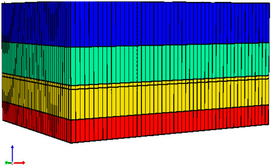
FIGURE 1. Reservoir model used in this study.
In addition, the well properties are defined as follows: the maximum injection pressure for injectors is 5,500 psi, the operating bottom hole pressure (BHP) for producers is 1800 psi, the maximum allowable gas–oil ratio (GOR) is 8000 SCF/bbl, and the maximum allowable water cut is 0.99. Also, a well radius of 0.625 ft and a skin factor of 1.5 were used, as suggested by many studies (Jacob, 1947; Bresciani et al., 2020). Figures 2, 3 show the relative permeability data used in this work for oil–water and gas–oil systems, respectively. Also, the relative permeability to oil was determined as a function of gas, water, and oil saturation, as shown in Figure 4. The relative permeability profiles were obtained using Correy’s model available in CMG software (Correy et al., 1956).
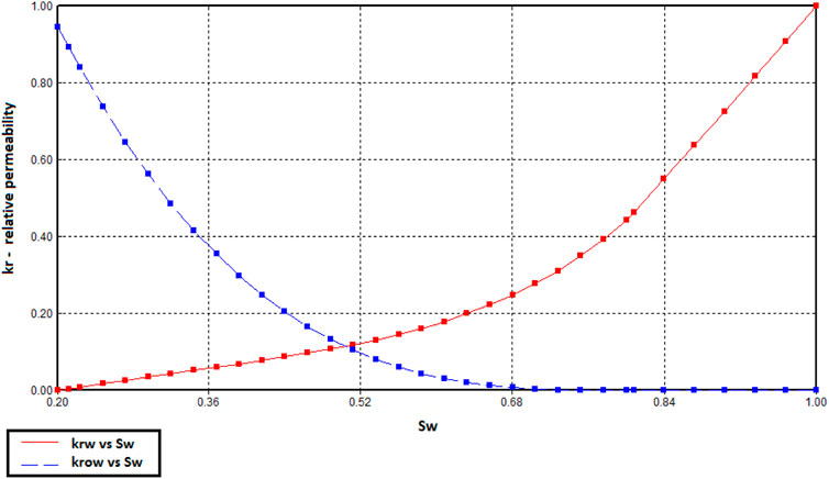
FIGURE 2. Water and oil relative permeability curves as a function of water saturation.
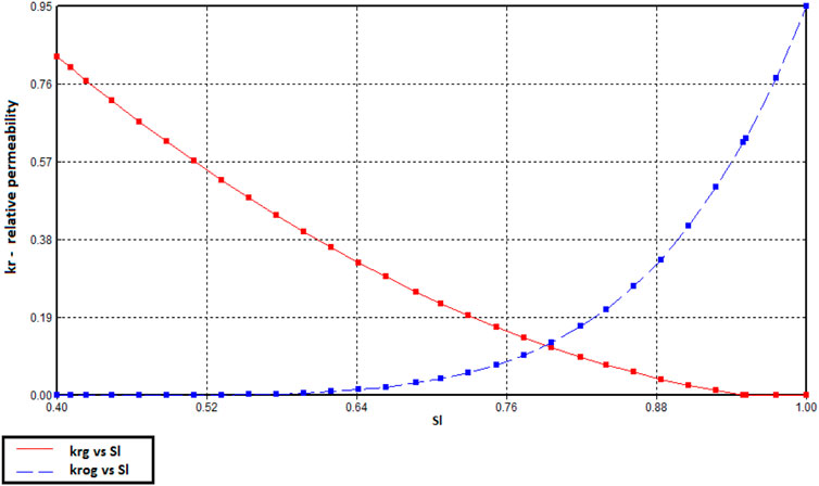
FIGURE 3. Gas and oil relative permeability curves as a function of gas saturation.
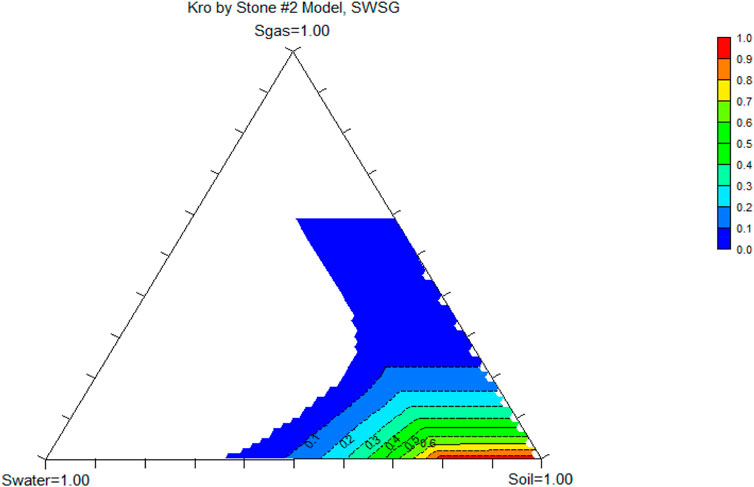
FIGURE 4. Oil relative permeability as a function of gas, water, and oil saturation.
Simulated Scenarios
The simulation work was carried out using CMG (Computer Modeling Group) software, and CMG Launcher 2015.10 (Builder 2015.1) was used in this work. Various scenarios of gas injection were simulated. All the simulations were started with the residual oil saturation (Sor) condition, representing depleted oil reservoir conditions. Three main scenarios were examined in this work: CO2 injection into the reservoir, CO2 injection into the aquifer, and CO2 injection into the aquifer followed by water injection. CO2 is highly soluble in water (Xing et al., 2012); the CO2 solubility in the formation brine is a strong function of pressure, temperature, and salinity (Duan and Sun 2003; Duan et al., 2006). Increasing the pressure showed a rapid increase in the CO2 solubility, while the CO2 solubility decreased with the increasing temperature or salinity. The models developed by Duan and Sun (2003) and Duan et al. (2006) were used in this work to estimate the CO2 solubility in water.
In addition, in all scenarios, three well schemes were utilized: horizontal wells (injectors and producers), vertical wells, and vertical injectors and horizontal producers. Therefore, a total of nine scenarios are discussed in this work. The profiles of oil recovery, reservoir pressure, and CO2 saturation are analyzed. The reservoir performance was examined for a period of 20 years. Around 7,928 tons of carbon dioxide can be sequestered within the reservoir/aquifer formations, on average. It should be noted that the wells’ number and locations can affect the simulation results; hence, a consistent reservoir/well model was used in this work in order to minimize the uncertainty and improve the work reliability.
Results and Discussion
In this work, three main cases were used by varying the location of CO2 injection from the reservoir to the water zone. Also, different well types were used including vertical, horizontal, and combinations for the production and injection wells. The profile of residual oil saturation and oil recovery is discussed in this part.
CO2 Injection Into the Reservoir
In this case, carbon dioxide is injected directly into the reservoir to enhance oil recovery through multiple mechanisms: oil swelling, viscosity reduction, and oil displacement. Three well configurations were used in this case. The first configuration is that both the producer and the injector were drilled horizontally, where one producer and one injector were used. The second configuration is that both producers and injectors were drilled vertically, where three producers and three injectors were used. The third configuration is that the injector wells were drilled vertically, while the producer wells were drilled horizontally, where three vertical gas injectors and one horizontal producer were used. Figure 5 shows the average oil saturation for the studied well configurations. In this work, the simulation duration is 20 years, and the maximum bottom hole pressure of 5,500 psi was used for the injectors, while a maximum oil production rate of 30000 bbl/day was defined for the producers. For all cases, the average oil saturation decreases with time until reaching an oil saturation less than 10%, indicating that CO2 injection is effectively enhancing the oil production. Using three injectors and three producers showed the lowest oil saturation, followed by using horizontal wells for injection and production. However, the case of using three vertical injectors and one horizontal producer showed relatively high residual saturation (around 9.5%) revealing relatively low oil recovery compared to other examined scenarios. Also, an injection period of 10 years could be selected as the optimum injection duration, as no further reduction was observed in the oil saturation after 10 years.
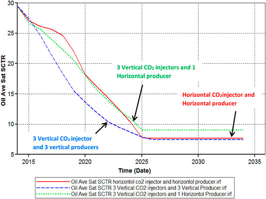
FIGURE 5. Average oil saturation as a function of time for the three studied well configurations.
Figure 6 shows the oil recovery factor for the studied well configurations; all cases show a recovery factor more than 65% of the original oil-in-place (OOIP). The highest oil recovery of 72% of the OOIP was achieved using three vertical injectors and three vertical producers, while using horizontal wells showed relatively comparable results: an oil recovery of 70% of the OOIP. However, using three vertical injectors and one horizontal producer showed the lowest oil recovery (around 66%) among the studied cases. The main reason for the difference in oil recovery for different scenarios could be the contact area between the wellbore and the reservoir. Usually, increasing this contact area can lead to an increase in oil recovery. Overall, all studied scenarios showed oil recovery more than 65% of the OOIP, indicating effective CO2 treatment.
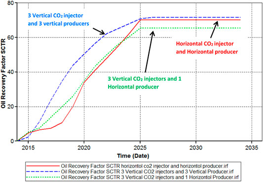
FIGURE 6. Oil recovery factor as a function of injection time for the three studied well configurations.
CO2 Injection Into the Aquifer
In this case, three well schemes were examined by changing the well type from horizontal to vertical for injectors and producers. The first case is that all wells were drilled horizontally, where one producer and one injector were used. The second case is that all wells were drilled vertically, where three producers and three injectors were used. Finally, horizontal producers and vertical injectors were studied, where three vertical gas injectors and one horizontal producer were used. Similar to the previous case of CO2 injection into the reservoir, a simulation time of 20 years was used to examine the recovery profiles. Also, the maximum pressure of 5,500 psi was used for the injectors, and the maximum production of 30000 bbl/day was defined.
Figure 7 shows the profiles of the residual oil saturation for the three studied scenarios. In all cases, CO2 was injected only into the aquifer and no CO2 was injected into the reservoir. It should be notated that a thin layer of low permeability is placed between the aquifer and the reservoir to enable the slow release of CO2 from the aquifer to the reservoir. For all cases, the minimum oil saturation was achieved after 10 years of injection, and no reduction was observed in oil saturation by continuing CO2 injection after 10 years. Therefore, the optimum CO2 injection duration could be selected as 10 years. Among all studied cases, three vertical injectors and three vertical producers showed the lowest oil saturation followed by the case of using one horizontal injector and one horizontal producer, where the residual oil saturation of around 9% was achieved. However, using three vertical injectors and one horizontal producer showed the poorest performance, where the residual oil saturation of 13% was obtained. Moreover, the oil recovery profiles for all studied cases are presented in Figure 8, where CO2 was injected only into the aquifer. Using three vertical injectors and three vertical producers showed the highest oil recovery of 69% of the OOIP, followed by using a horizontal injector and producer, where an oil recovery of 68% of the original oil-in-place was observed. However, using three vertical injectors and one horizontal producer gave an oil recovery of 58% of the OOIP. Overall, using three vertical injectors and three vertical producers or using one horizontal injector and one horizontal producer showed very efficient oil recovery as indicated by the residual oil saturation and oil recovery profiles.
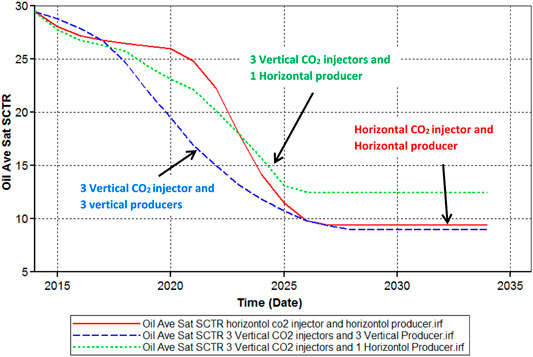
FIGURE 7. Average oil saturation against time for the three examined cases. CO2 was injected into the aquifer for all cases.
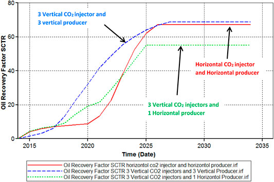
FIGURE 8. Oil recovery factor as a function of time for the three examined cases. CO2 was injected only into the aquifer for all cases.
CO2 Injection Into the Aquifer Assisted by Waterflooding
The performance of CO2 into the aquifer was assisted by injecting water using a sequential approach; CO2 was injected, and then waterflooding was implemented. Different well types were used similar to the previously discussed cases; all wells are horizontal, all wells are vertical, and producers are horizontal and injectors are vertical. Also, in all scenarios, a maximum injection pressure of 5,500 psi was used, and a maximum production rate of 30000 bbl/day was applied. Figure 9 shows the average oil saturation during the injection of CO2 followed by waterflooding treatment. Using horizontal producers and injectors outperforms all other scenarios, where the residual oil saturation of 21% was achieved as opposed to 23.5% observed for other cases. In contrast to all previous scenarios, the residual oil saturation decreases with time even after 10 years of injection. Also, applying waterflooding showed lower performance, which could be attributed to increasing the volume of trapped oil within the injected water. Furthermore, the oil recovery factor for all studied cases is shown in Figure 10. More oil is recovered with time, and no recovery plateau is observed. However, for all cases, the maximum oil recovery is less than 30% of the OOIP indicating poor recovery performance. Injecting water could have resulted in the trapping of more oil. Also, CO2 is in contact with less volume of oil. In this case, the minimum oil recovery is 18%, and the maximum recovery is around 28%, which was achieved using one horizontal injector and one horizontal producer. Overall, all cases of vertical and horizontal wells showed lower recovery compared to the cases where waterflooding was not implemented.
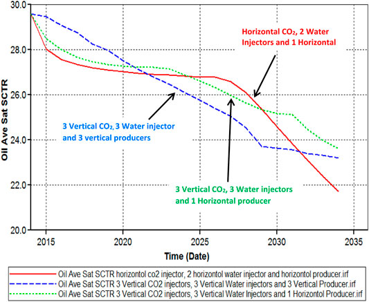
FIGURE 9. Average oil saturation vs. time for the three examined cases. In all cases, CO2 was injected into the aquifer which was followed by water injection.
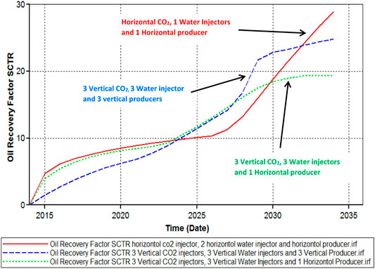
FIGURE 10. Oil recovery factor vs. time for the three examined cases. In all cases, CO2 was injected into the aquifer which was followed by water injection.
Comparative Analysis
The oil recovery for all studied scenarios (nine cases) is listed in Table 1. It should be noted that the same number of wells and configurations was used in the three main scenarios (CO2 injection into the reservoir, CO2 injection into the aquifer, and CO2 injection into the aquifer assisted by waterflooding) in order to minimize the uncertainty of the simulation results. The highest oil recovery (73% of the OOIP) was obtained using CO2 injection into the depleted reservoir and utilizing three vertical injectors and three vertical producers, while the minimum oil recovery (18% of the OOIP) was achieved for injecting CO2 into the aquifer followed by waterflooding, where three vertical injectors and one horizontal producer were used. Also, injecting CO2 into the aquifer without applying waterflooding showed a comparable oil recovery compared to the case of direct injection of CO2 into the reservoir. The simulation results showed that the injected CO2 will be stored within the reservoir and aquifer systems, as a small amount of CO2 (around 12% of the injected volume) was produced. Around 80–90% of the injected CO2 will be sequestered in the reservoir formations, and the produced gases can be re-injected into the reservoir. Utilizing a constant injection approach, the estimated volume of CO2 that can be sequestered in the underground formations is around 7,928 tons, on average.
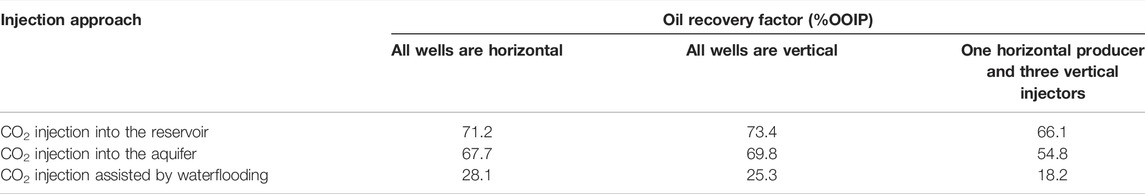
TABLE 1. Oil recovery factors for all studied scenarios.
Moreover, the performance of CO2 injection is compared to that of the conventional waterflooding treatment. Figure 11 shows the oil recovery factor vs. time for CO2 injection into the aquifer and waterflooding cases, where all wells are drilled horizontally. CO2 injection showed considerably higher recovery compared to water flooding: 68 vs. 12% of the OOIP. The CO2 approach outperforms water injection although one horizontal well was used for injecting CO2, while two horizontal wells were used for water injection. Moreover, the injection of CO2 into the aquifer provides dual benefits: CO2 sequestration and attractive oil production. Injecting carbon dioxide into the aquifer results in slow release of CO2, which will interact with the oil and reduce the oil viscosity.
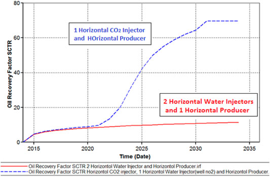
FIGURE 11. Oil recovery factor vs. time for CO2 injection and waterflooding cases. All wells were drilled horizontally.
In this work, the geochemical reactions between the injected carbon dioxide and the reservoir/aquifer systems were not examined. Injecting CO2 may alter the rock properties such as porosity and permeability, due to the geochemical reactions (Cui et al., 2021). Hence, it is recommended to conduct a geochemical study to assess the changes in the reservoir and aquifer properties. Moreover, the distance between the injection and production wells can significantly affect the oil recovery profiles. However, in this work, we did not change the well location, as the main objective of the current study is to compare the performance of three main scenarios (CO2 injection into the reservoir, CO2 injection into the aquifer, and CO2 injection into the aquifer followed by water injection). Further studies can be carried out to assess the impact of well locations on oil recovery during different CO2 injection approaches.
Conclusion
This work examines the performance of CO2 injection in enhancing oil recovery from depleted reservoirs. The CMG (Computer Modeling Group) software package was used to investigate different injection scenarios. Based on the conducted simulations, the following conclusions can be drawn:
• The highest oil recovery of 73% of the original oil-in-place (OOIP) was obtained by injecting CO2 into the reservoir, utilizing vertical injectors and producers.
• During EOR treatments, around 7,928 tons of carbon dioxide can be sequestered in the reservoir/aquifer systems, on average.
• Injecting CO2 into the water zone showed a very successful approach and enhanced the oil recovery by around 68–70% of the OOIP.
• In all studied cases, using horizontal produces and injectors gave more oil recovery than that using vertical wells, under the same conditions.
• CO2 injection outperformed conventional waterflooding, where 68 and 12% of the OOIP were recovered, respectively.
• Overall, injection of CO2 into the depleted reservoir can provide dual benefits of CO2 sequestration and enhanced oil recovery.
• Further work can be conducted to evaluate the geochemical interactions and assess the impact of wells’ locations on the oil recovery profiles.
Data Availability Statement
The original contributions presented in the study are included in the article/Supplementary Material, further inquiries can be directed to the corresponding authors.
Author Contributions
MA performed the work and wrote the original draft. AH analyzed the data and prepared the manuscript. AH, SP, and MM validated the results. MM supervised the work. NS helped in the simulation work. SP and MM reviewed the manuscript.
Conflict of Interest
The authors declare that the research was conducted in the absence of any commercial or financial relationships that could be construed as a potential conflict of interest.
Publisher’s Note
All claims expressed in this article are solely those of the authors and do not necessarily represent those of their affiliated organizations, or those of the publisher, the editors, and the reviewers. Any product that may be evaluated in this article, or claim that may be made by its manufacturer, is not guaranteed or endorsed by the publisher.
Acknowledgments
The College of Petroleum and Geoscience at King Fahd University of Petroleum and Minerals is acknowledged for the support and permission to publish this work.
References
Abdelgawad, K. Z., and Mahmoud, M. A. (2015). “March. In-Situ Generation of CO2 to Eliminate the Problem of Gravity Override in EOR of Carbonate Reservoirs,” in SPE Middle East Oil & Gas Show and Conference (Manama, Bahrain: OnePetro).
Alam, M. M., Mahmoud, M., and Sibaweihi, N. (2015). “March. A Slow Release CO2 for Enhanced Oil Recovery in Carbonate Reservoirs,” in SPE Middle East Oil & Gas Show and Conference (Manama, Bahrain: OnePetro).
Ampomah, W., Balch, R. S., Grigg, R. B., Cather, M., Will, R. A., and Lee, S. Y. (2016). “May. Optimization of CO2-EOR Process in Partially Depleted Oil Reservoirs,” in SPE Western Regional Meeting (Anchorage, AK: OnePetro).
Bennion, D. B., and Bachu, S. (2006). “September. Dependence on Temperature, Pressure, and Salinity of the IFT and Relative Permeability Displacement Characteristics of CO2 Injected in Deep saline Aquifers,” in SPE Annual Technical Conference and Exhibition (San Antonio, TX: OnePetro).
Bresciani, E., Shandilya, R. N., Kang, P. K., and Lee, S. (2020). Well Radius of Influence and Radius of Investigation: What Exactly Are They and How to Estimate Them? J. Hydrol. 583, 124646. doi:10.1016/j.jhydrol.2020.124646
Brock, W. R., and Bryan, L. A. (19891972-1987). in Low Permeability Reservoirs Symposium (Denver, CO: OnePetro). March. Summary Results of CO2 EOR Field Tests.
Chang, S.-H., and Grigg, R. B. (1999). Effects of Foam Quality and Flow Rate on CO2-Foam Behavior at Reservoir Temperature and Pressure. SPE Reservoir Eval. Eng. 2 (03), 248–254. doi:10.2118/56856-pa
Chen, Y., Sari, A., Xie, Q., and Saeedi, A. (2019). Insights into the Wettability Alteration of CO2-assisted EOR in Carbonate Reservoirs. J. Mol. Liquids 279, 420–426. doi:10.1016/j.molliq.2019.01.112
Cherepovitsyn, A., Fedoseev, S., Tcvetkov, P., Sidorova, K., and Kraslawski, A. (2018). Potential of Russian Regions to Implement CO2-Enhanced Oil Recovery. Energies 11 (6), 1528. doi:10.3390/en11061528
Chiquet, P., Broseta, D., and Thibeau, S. (2007). Wettability Alteration of Caprock Minerals by Carbon Dioxide. Geofluids 7 (2), 112–122. doi:10.1111/j.1468-8123.2007.00168.x
Corey, A. T., Rathjens, C. H., Henderson, J. H., and Wyllie, M. R. J. (1956). Three-phase Relative Permeability. J. Pet. Technol. 8 (11), 63–65. doi:10.2118/737-g
Cui, G., Zhu, L., Zhou, Q., Ren, S., and Wang, J. (2021). Geochemical Reactions and Their Effect on CO2 Storage Efficiency during the Whole Process of CO2 EOR and Subsequent Storage. Int. J. Greenhouse Gas Control. 108, 103335. doi:10.1016/j.ijggc.2021.103335
Dai, Z., Viswanathan, H., Xiao, T., Middleton, R., Pan, F., Ampomah, W., et al. (2017). CO2 Sequestration and Enhanced Oil Recovery at Depleted Oil/Gas Reservoirs. Energ. Proced. 114, 6957–6967. doi:10.1016/j.egypro.2017.08.034
Dong, K., Dong, X., Jiang, Q., and Zhao, J. (2021). Valuing the Greenhouse Effect of Political Risks: the Global Case. Appl. Econ. 53 (31), 3604–3618. doi:10.1080/00036846.2021.1883543
Duan, Z., and Sun, R. (2003). An Improved Model Calculating CO2 Solubility in Pure Water and Aqueous NaCl Solutions from 273 to 533 K and from 0 to 2000 Bar. Chem. Geology. 193 (3-4), 257–271. doi:10.1016/s0009-2541(02)00263-2
Duan, Z., Sun, R., Zhu, C., and Chou, I. M. (2006). An Improved Model for the Calculation of CO2 Solubility in Aqueous Solutions Containing Na+, K+, Ca2+, Mg2+, Cl−, and SO42. Mar. Chem. 98 (2-4), 131–139. doi:10.1016/j.marchem.2005.09.001
Dudek, J., Janiga, D., and Wojnarowski, P. (2021). Optimization of CO2-EOR Process Management in Polish Mature Reservoirs Using Smart Well Technology. J. Pet. Sci. Eng. 197, 108060. doi:10.1016/j.petrol.2020.108060
Ettehadtavakkol, A., Lake, L. W., and Bryant, S. L. (2014). CO2-EOR and Storage Design Optimization. Int. J. Greenhouse Gas Control. 25, 79–92. doi:10.1016/j.ijggc.2014.04.006
Farokhpoor, R., Bjørkvik, B. J. A., Lindeberg, E., and Torsæter, O. (2013). Wettability Behaviour of CO2 at Storage Conditions. Int. J. Greenhouse Gas Control. 12, 18–25. doi:10.1016/j.ijggc.2012.11.003
Goel, A., and Bhatt, R. (2012). Causes and Consequences of Global Warming. Int. J. Life Sci. Biotechnol. Pharma Res. 1 (1), 27–31.
Gozalpour, F., Ren, S. R., and Tohidi, B. (2005). CO2Eor and Storage in Oil Reservoir. Oil Gas Sci. Technol. - Rev. IFP 60 (3), 537–546. doi:10.2516/ogst:2005036
Hafez, M., Ratanpara, A. P., Martiniere, Y., Dagois, M., Ghazvini, M., Kavosi, M., et al. (2021). CO2-monoethanolamine-induced Oil Swelling and Viscosity Reduction for Enhanced Oil Recovery. J. Pet. Sci. Eng. 206, 109022. doi:10.1016/j.petrol.2021.109022
Hamza, A., Hussein, I. A., Al-Marri, M. J., Mahmoud, M., Shawabkeh, R., and Aparicio, S. (2021). CO2 Enhanced Gas Recovery and Sequestration in Depleted Gas Reservoirs: A Review. J. Pet. Sci. Eng. 196, 107685. doi:10.1016/j.petrol.2020.107685
Hassanpouryouzband, A., Joonaki, E., Edlmann, K., and Haszeldine, R. S. (2021). Offshore Geological Storage of Hydrogen: Is This Our Best Option to Achieve Net-Zero? ACS Energ. Lett. 6 (6), 2181–2186. doi:10.1021/acsenergylett.1c00845
Hassanpouryouzband, A., Yang, J., Tohidi, B., Chuvilin, E., Istomin, V., Bukhanov, B., et al. (2018). CO2 Capture by Injection of Flue Gas or CO2-N2 Mixtures into Hydrate Reservoirs: Dependence of CO2 Capture Efficiency on Gas Hydrate Reservoir Conditions. Environ. Sci. Technol. 52 (7), 4324–4330. doi:10.1021/acs.est.7b05784
Hassanpouryouzband, A., Yang, J., Tohidi, B., Chuvilin, E., Istomin, V., and Bukhanov, B. (2019). Geological CO2 Capture and Storage with Flue Gas Hydrate Formation in Frozen and Unfrozen Sediments: Method Development, Real Time-Scale Kinetic Characteristics, Efficiency, and Clathrate Structural Transition. ACS Sustain. Chem. Eng. 7 (5), 5338–5345. doi:10.1021/acssuschemeng.8b06374
Hawkes, C. D., McLellan, P. J., Zimmer, U., and Bachu, S. (2004). “June. Geomechanical Factors Affecting Geological Storage of CO2 in Depleted Oil and Gas Reservoirs,” in Canadian International Petroleum Conference (Calgary, Alberta: OnePetro).
Imanovs, E., Krevor, S., and Mojaddam Zadeh, A. (2020). “December. CO2-EOR and Storage Potentials in Depleted Reservoirs in the Norwegian continental Shelf NCS,” in SPE Europec (OnePetro.
Jacob, C. E. (1947). Drawdown Test to Determine Effective Radius of artesian Well. T. Am. Soc. Civ. Eng. 112 (1), 1047–1064. doi:10.1061/taceat.0006033
Jeffry, L., Ong, M. Y., Nomanbhay, S., Mofijur, M., Mubashir, M., and Show, P. L. (2021). Greenhouse Gases Utilization: A Review. Fuel 301, 121017. doi:10.1016/j.fuel.2021.121017
Jia, B., Tsau, J.-S., and Barati, R. (2019). A Review of the Current Progress of CO2 Injection EOR and Carbon Storage in Shale Oil Reservoirs. Fuel 236, 404–427. doi:10.1016/j.fuel.2018.08.103
Le, V. Q., Nguyen, Q. P., and Sanders, A. (2008). “April. A Novel Foam Concept with CO2 Dissolved Surfactants,” in SPE Symposium on Improved Oil Recovery (Tulsa, OK: OnePetro).
Orr, F. M., and Taber, J. J. (1984). Use of Carbon Dioxide in Enhanced Oil Recovery. Science 224 (4649), 563–569. doi:10.1126/science.224.4649.563
Perera, M., Gamage, R., Rathnaweera, T., Ranathunga, A., Koay, A., and Choi, X. (2016). A Review of CO2-Enhanced Oil Recovery with a Simulated Sensitivity Analysis. Energies 9 (7), 481. doi:10.3390/en9070481
Raza, A., Gholami, R., Rezaee, R., Bing, C. H., Nagarajan, R., and Hamid, M. A. (2017). Assessment of CO 2 Residual Trapping in Depleted Reservoirs Used for Geosequestration. J. Nat. Gas Sci. Eng. 43, 137–155. doi:10.1016/j.jngse.2017.04.001
Rehman, A., Ma, H., Irfan, M., and Ahmad, M. (2020). Does Carbon Dioxide, Methane, Nitrous Oxide, and GHG Emissions Influence the Agriculture? Evidence from China. Environ. Sci. Pollut. Res. 27 (23), 28768–28779. doi:10.1007/s11356-020-08912-z
Rezaei, F., Rezaei, A., Jafari, S., Hemmati-Sarapardeh, A., Mohammadi, A. H., and Zendehboudi, S. (2021). On the Evaluation of Interfacial Tension (IFT) of CO2-Paraffin System for Enhanced Oil Recovery Process: Comparison of Empirical Correlations, Soft Computing Approaches, and Parachor Model. Energies 14 (11), 3045. doi:10.3390/en14113045
Shi, L., Liu, P., Shen, D., Liu, P., Xi, C., and Zhang, Y. (2019). Improving Heavy Oil Recovery Using a Top-Driving, CO2-assisted Hot-Water Flooding Method in Deep and Pressure-Depleted Reservoirs. J. Pet. Sci. Eng. 173, 922–931. doi:10.1016/j.petrol.2018.10.088
Shiau, B. J., Hsu, T. P., Roberts, B. L., and Harwell, J. H. (2010). “April. Improved Chemical Flood Efficiency by In Situ CO2 Generation,” in SPE Improved Oil Recovery Symposium (Tulsa, OK: OnePetro).
Talebian, S. H., Masoudi, R., Tan, I. M., and Zitha, P. L. J. (2014). Foam Assisted CO2-EOR: A Review of Concept, Challenges, and Future Prospects. J. Pet. Sci. Eng. 120, 202–215. doi:10.1016/j.petrol.2014.05.013
Talebian, S. H., Masoudi, R., Tan, I. M., and Zitha, P. L. (2013). “July. Foam Assisted CO2-EOR; Concepts, Challenges and Applications,” in SPE Enhanced Oil Recovery Conference (Kuala Lumpur, Malaysia: OnePetro).
Wang, S., Chen, C., Li, K., Yuan, N., Shiau, B., and Harwell, J. H. (2019). In Situ CO2 Enhanced Oil Recovery: Parameters Affecting Reaction Kinetics and Recovery Performance. Energy Fuels 33 (5), 3844–3854. doi:10.1021/acs.energyfuels.8b03734
Wang, S., Chen, C., Shiau, B., and Harwell, J. H. (2018). In-situ CO2 Generation for EOR by Using Urea as a Gas Generation Agent. Fuel 217, 499–507. doi:10.1016/j.fuel.2017.12.103
Wang, S., Liang, Y., Feng, Q., and Javadpour, F. (2022). Sticky Layers Affect Oil Transport through the Nanopores of Realistic Shale Kerogen. Fuel 310, 122480. doi:10.1016/j.fuel.2021.122480
Wang, S., Qin, C., Feng, Q., Javadpour, F., and Rui, Z. (2021a). A Framework for Predicting the Production Performance of Unconventional Resources Using Deep Learning. Appl. Energ. 295, 117016. doi:10.1016/j.apenergy.2021.117016
Wang, S., Yao, X., Feng, Q., Javadpour, F., Yang, Y., Xue, Q., et al. (2021b). Molecular Insights into Carbon Dioxide Enhanced Multi-Component Shale Gas Recovery and its Sequestration in Realistic Kerogen. Chem. Eng. J. 425, 130292. doi:10.1016/j.cej.2021.130292
Wang, Y., Hou, J., and Tang, Y. (2016). In-situ CO 2 Generation Huff-N-Puff for Enhanced Oil Recovery: Laboratory Experiments and Numerical Simulations. J. Pet. Sci. Eng. 145, 183–193. doi:10.1016/j.petrol.2016.04.002
Wei, B., Gao, H., Pu, W., Zhao, F., Li, Y., Jin, F., et al. (2017). Interactions and Phase Behaviors between Oleic Phase and CO 2 from Swelling to Miscibility in CO 2 -based Enhanced Oil Recovery (EOR) Process: A Comprehensive Visualization Study. J. Mol. Liquids 232, 277–284. doi:10.1016/j.molliq.2017.02.090
Keywords: enhanced oil recovery, CO2 injection, dual benefits, high oil recovery, CO2 sequestration
Citation: Alam MMM, Hassan A, Mahmoud M, Sibaweihi N and Patil S (2022) Dual Benefits of Enhanced Oil Recovery and CO2 Sequestration: The Impact of CO2 Injection Approach on Oil Recovery. Front. Energy Res. 10:877212. doi: 10.3389/fenrg.2022.877212
Received: 16 February 2022; Accepted: 21 March 2022;
Published: 27 April 2022.
Edited by:
Zhenkun Hou, Guangdong University of Technology, ChinaReviewed by:
Sen Wang, China University of Petroleum, Huadong, ChinaAliakbar Hassanpouryouzband, University of Edinburgh, United Kingdom
Copyright © 2022 Alam, Hassan, Mahmoud, Sibaweihi and Patil. This is an open-access article distributed under the terms of the Creative Commons Attribution License (CC BY). The use, distribution or reproduction in other forums is permitted, provided the original author(s) and the copyright owner(s) are credited and that the original publication in this journal is cited, in accordance with accepted academic practice. No use, distribution or reproduction is permitted which does not comply with these terms.
*Correspondence: Amjed Hassan, YW1qZWQubW9oYW1tZWRAa2Z1cG0uZWR1LnNh; Mohamed Mahmoud, bW1haG1vdWRAa2Z1cG0uZWR1LnNh; Shirish Patil, cGF0aWxAa2Z1cG0uZWR1LnNh