- 1School of Mechanical Engineering, NanJing Institute of Technology, Nanjing, China
- 2Key Laboratory of Aerodynamic Noise Control, China Aerodynamics Research and Development Center, Mianyang, China
- 3School of Power and Energy, Northwestern Polytechnical University, Xi’an, China
The influence of different test methods on the accuracy of mode identification is not clear, and it is necessary to explore the error transfer characteristics in mode decomposition of fan noise. Numerical and experimental research studies are carried out on the advantages and disadvantages of radial rake and axial microphone array and error transmission characteristics in mode decomposition. In the numerical study, the error transmission characteristics of different arrays are investigated by adding random disturbances to the artificial sound field, so as to evaluate the applicability and limitations of the two typical arrays in mode identification based on the error analysis theory. The mode recognition error of the single-stage axial flow fan is investigated experimentally using the designed radial rakes and axial arrays. The results show that although the radial rake can directly measure the radial distribution of the modal amplitude, it has a large error in the mode identification at low frequencies. Compared with the radial rake, axial array will take more priority in practical applications. The accuracy of the axial microphone array in mode recognition strongly depends on the axial spacing of the array measuring sensors. The small deviations in the mode identification when applying the two typical arrays are caused by the different signal-to-noise ratio of the sound pressure signals acquired by the two arrays and their discriminative sensitivities to the duct airflow. Based on the obtained modal identification error characteristics, an effective mode identification method can be proposed to help fan noise reduction design.
1 Introduction
The acoustic wave propagates in the form of modal waves in the duct, and the number of cut-on modal waves depends on the duct geometry, sound wave frequency, the airflow velocity, and the acoustic boundary conditions of the duct. Aero-engine noise includes tonal noise (such as rotor self-noise, buzzer, and rotor-static interference noise) and broadband noise (Qiao, 2010). The method of mode decomposition is widely used to investigate the generation mechanism of tonal noise and broadband noise in the flow duct. For radial modal analysis in tonal noise, starting in the 1960s, a number of experimental measurement methods have been developed (Bolleter and Crocker, 1972; Bolleter et al., 1973; Moore, 1979; Holste and Neise, 1997; Enghardt et al., 1999; Lan et al., 2002). These methods have different limitations considering the solvable modal order range, the accuracy of analysis results, and the complexity of method application. Ideally, radial mode decomposition is achieved by far-field measurements (Farassat et al., 2001), as this is easy to achieve in practical measurements and is not limited by size. However, considering the errors introduced by the analytical model when applied to the real engine geometry and the time-consuming in numerical calculation of the transfer function between the inlet (or outlet) and the far field, nowadays, the radial mode decomposition of the sound field at low frequencies is usually performed by arranging a large number of sensors in the duct (Tapken and Enghardt, 2006), and the radial mode distribution results in the duct are obtained by inversely processing the measured sound pressure data. The German Aerospace Academy (DLR) successfully used this method to measure tonal noise in the ducts of fans (Enghardt et al., 2002), low-pressure compressors (Enghardt et al., 2005), and low-pressure turbines (Enghardt et al., 2001).
There are two types of commonly used microphone arrays: radial rakes and axial arrays. The radial rake can directly measure the distribution of modal waves in the radial direction, and it is easier to realize the modal sound power in terms of numerical solution. Enghardt et al. (2001), Sutliff, (2005), Dahl et al. (2013), and Heidelberg and Hall, (1996) used a rotating rake array to measure the sound field in the flow duct, but when placed upstream, its wake will interfere with the original flow field and pollute the sound field. Joppa, (1987) developed a practical method to measure the sound pressure using an array of equally spaced axial microphones flush-mounted on the duct wall, and the distribution of the fan discrete tonal noise can be obtained by using the axial microphones (Wang et al., 2014; Xu et al., 2018), which can perform circumferential modal analysis of compressor rotational instability (Zhou et al., 2015) and compressor fault diagnosis (Cheng et al., 2019). Zillmann and Tapken, (2009) and Tapken et al. (2009) used a circumferentially rotatable axial array to measure fan noise with very large bypass ratios. Yardley (Yardley, 1974) suggested that the microphones should be installed on the duct wall and pointed out that the mode identification of fan duct noise can be carried out by sound pressure measurement at multiple axial positions, and the duct acoustic performance analysis can be carried out according to the acoustic modal amplitude (Wagih Nashed et al., 2018) and sound field reconstruction (Liu et al., 2018). For both radial rakes and axial arrays, the mode identification is achieved by inverting the coefficient matrix between the sound pressure at the measuring sensors and the radial modal amplitudes. Acoustic mode identification is also closely related to the airflow turbulence in the duct (Kan et al., 2021). Under the measured modal coherence characteristics, the accuracy in acoustic mode identification can be effectively improved. However, the influence of different testing methods on mode identification accuracy is not clear, and the error transmission characteristics of different microphone arrays in mode identification are not analyzed in detail.
Based on the modal decomposition theory, the error transfer characteristics of two typical kinds of arrays in turbomachinery noise measurement is investigated in this study. The influence of different microphone arrays on the accuracy of acoustic mode identification is numerically studied, and the design criteria of the axial microphone array are established. Based on the error characteristics shown in the results, acoustic mode identification of a single-stage axial flow fan is investigated experimentally through the processing of rotating radial rakes and axial arrays. Accordingly, effective measures to reduce the mode identification error are proposed.
2 Measurement Theory
2.1 Acoustic Mode Recognition Method
For acoustic propagation in an incompressible circular/annular duct, the acoustic propagation equation in a circular/annular duct can be written as follows:
where c is the speed of sound and
The axial wavenumber
The modal characteristic functions satisfy the following:
In which
In the formula,
Therefore, the cross-spectrum of the modal amplitudes can be written as follows:
where
In the formula,
The solvability and stability of Eq. 10 and the error transfer characteristics of the system are closely related to the condition number of the square matrix. The condition number depends on many factors: the number of cut-on modes, frequency, hub-to-shroud ratio, airflow parameters, and the shape of the design array. Therefore, it becomes necessary to evaluate the quality of mode decomposition by condition number analysis.
2.2 Error Analysis Theory
In order to explore the limitations of different array schemes in mode identification measurement, the numerical method is used to study the error characteristics of radial rakes and axial arrays in mode identification. By analyzing the coefficient matrix condition number, the influence of the axial spacing in the array design on the mode identification is studied and the error transfer characteristics of different arrays during mode decomposition are investigated by superimposing random disturbances in the artificial sound field, which thus provides theoretical guidance for mode identification of duct noise.
The accuracy of the calculation results in the mode identification is related to the condition number of the matrix. It determines the upper bound of the error transfer coefficient of the system of Eq. 10:
The tilde character ∼ represents the perturbation of the circumferential modal amplitude
The matrix condition number
It is easy to know that the larger the relative accuracy value, the larger the relative error in mode identification.
2.3 Error Analysis Process
Numerical simulation is used to investigate the influence of the measurement error on the final output of the system in the experimental test. Generally speaking, measurement error is divided into systematic error and random error, but only the influence of random measurement error is considered here, and the random error added in the simulation satisfies the Gaussian distribution.
The numerical simulation process is mainly divided into four steps: 1) based on the given radial modal amplitude
where
The modal amplitude
2.4 Array Design Scheme
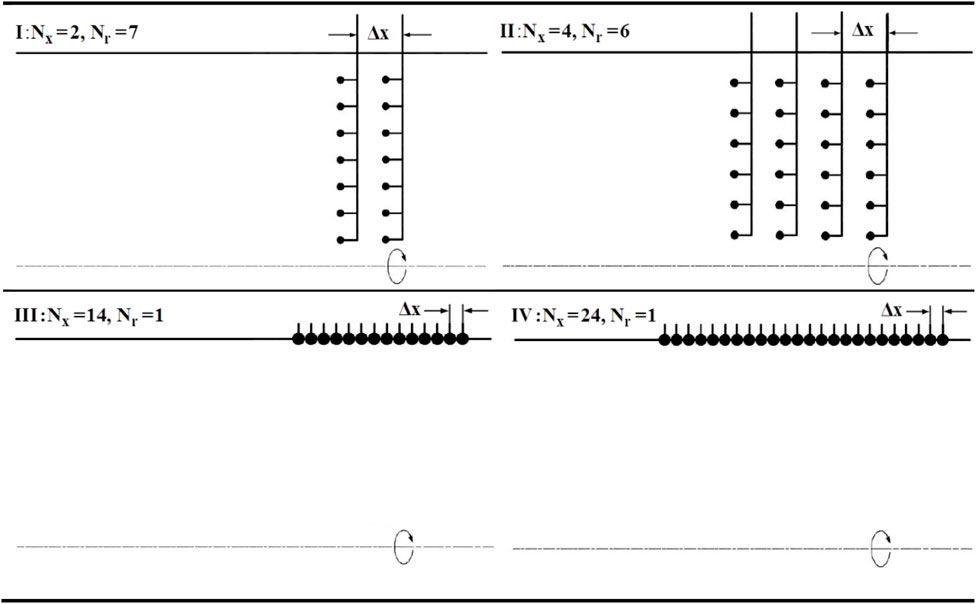
Radial rakes and axial microphone arrays have been mainly developed for acoustic mode identification of engine noise. Therefore, four array design schemes shown in Figure 1 are investigated in this section, the array is represented by prefix A, and different schemes are distinguished by Roman numbers. Generally, the experimental measurement section is arranged in the fan inlet section, so the hub ratio of the four arrays is set as
I: Array scheme A-I consists of radial rakes at
II: The array scheme A-II consists of four radial rakes at
III: The array scheme A-III consists of an axial array mounted on the duct wall. There are
IV: The array scheme A-IV is similar to A-III, in which the microphones are arranged on the duct wall, but the total number of microphones is different.
A-I and A-III consist of the same number of microphones
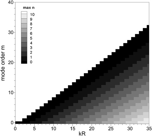
Considering the number of measuring points
The frequency range for the numerical study is
3 Mode Identification Error Simulation
3.1 Mode Identification Relative Accuracy
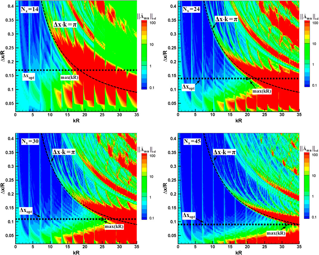
Figure 3 shows the condition number results of the four array schemes at m = 0 circumferential mode; m = 0 mode is selected for analysis because more radial modes can be cut on at m = 0. The results show that the condition number is very sensitive to the axial spacing of the array as well as the frequency. Comparing the relative accuracy results of the four arrays, it can be found that the corresponding frequencies appearing with poor relative accuracy are roughly the same, while the A-I array is better than the other three arrays initially. It can be found that the poor relative accuracy is caused by insufficient sampling of the phase information of the acoustic wave in the axial direction by the array schemes. Unlike the orthogonality of the radial modal eigenfunctions, the axial wavenumbers are not orthogonal, so frequencies with poor relative accuracy in mode identification appear at the following:
where
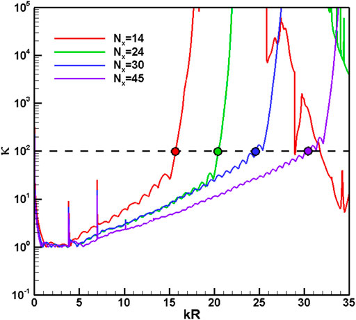
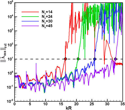
Figures 4, 5 present the condition number and relative accuracy results for the four axial arrays at the optimum spacing, respectively. As the frequency increases, the condition number of the axial array presents a monotonically and steadily increasing trend, and the greater the number of axial measuring points in the array, the slower the increasing trend. Different from the spectral characteristics of the condition number, the relative accuracy results show an upward trend of oscillation as the frequency increases. When the threshold values of the condition number and the relative accuracy are given, it can be found by comparing Figures 4, 5 that the upper limit of frequency
3.2 Sensitivity of Relative Accuracy of Mode Identification to Modal Order
The previous section only studied the relationship between the axial spacing
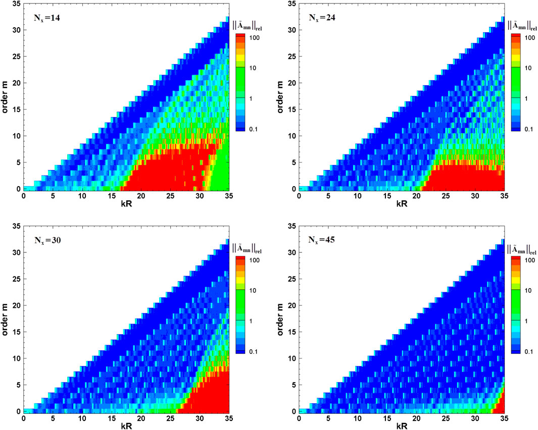
FIGURE 6. Relative accuracy of the four axial arrays under optimum spacing in different circumferential mode decompositions.
4 Array Design Method in Mode Decomposition
4.1 Standard Deviation in Mode Decomposition
In the turbomachinery noise mode identification experiment, the amplitude of each radial mode is what everyone cares about most. The investigations in the previous chapter can only predict the overall accuracy of each radial mode. In this section, modal standard deviation is used to investigate the accuracy of different microphone arrays in mode identification.
Figure 7 shows the standard deviation
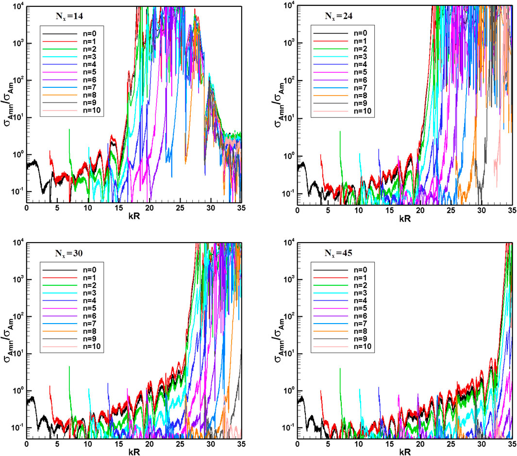
FIGURE 7. Relative standard deviations
4.2 Guidelines for Microphone Array Design
The previous section presents the upper frequency limit of the four axial arrays for mode identification and the optimal spacing in array scheme design. In general, as the number of measuring points increases, the frequency range that can be accurately solved in mode identification also increases. However, the array design scheme will seriously affect the solution accuracy in the mode identification, so it is necessary to investigate the design criteria of the axial array.
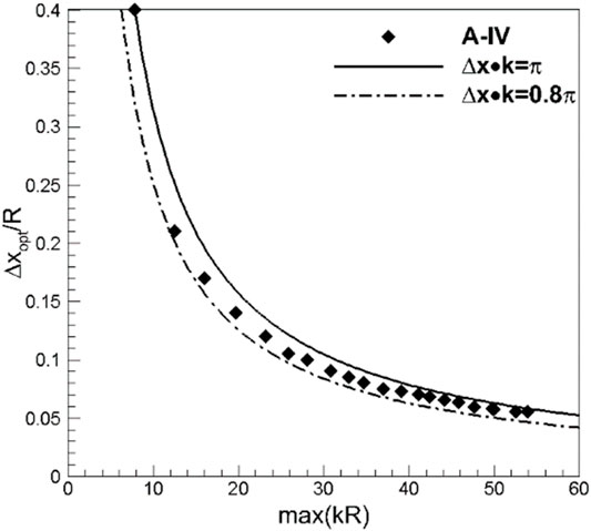
In the process of array design, two main problems need to be solved: (a) when the number of measuring sensors is given, how to quickly determine the distance between the measuring sensors, so that the mode identification measurement in a wider frequency range can be realized within a certain error limit; (b) how to quickly determine the number of measuring sensors required by the array design when the frequency of interest is given. For the first problem, it can be achieved by calculating the optimal axial spacing
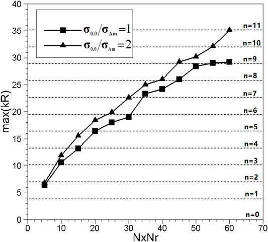
For the second problem, this section investigates the dependence of the frequency upper limit
5 Experimental Analysis of Mode Identification Error
Regarding the influence of different microphone arrays on the mode identification accuracy, after numerical investigation of error variation, this section will conduct an experimental measurement based on the axial fan test bench. The main purpose of the research is to conduct an experimental study on the differences in mode identification between axial arrays (Axial Arrays, AA) and radial rakes (Radial Rakes, RR) installed, respectively, in the fan inlet section.
5.1 Acoustic Test Bench
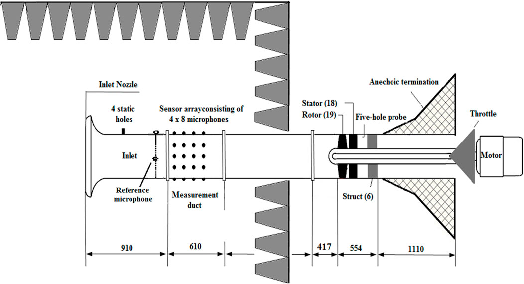
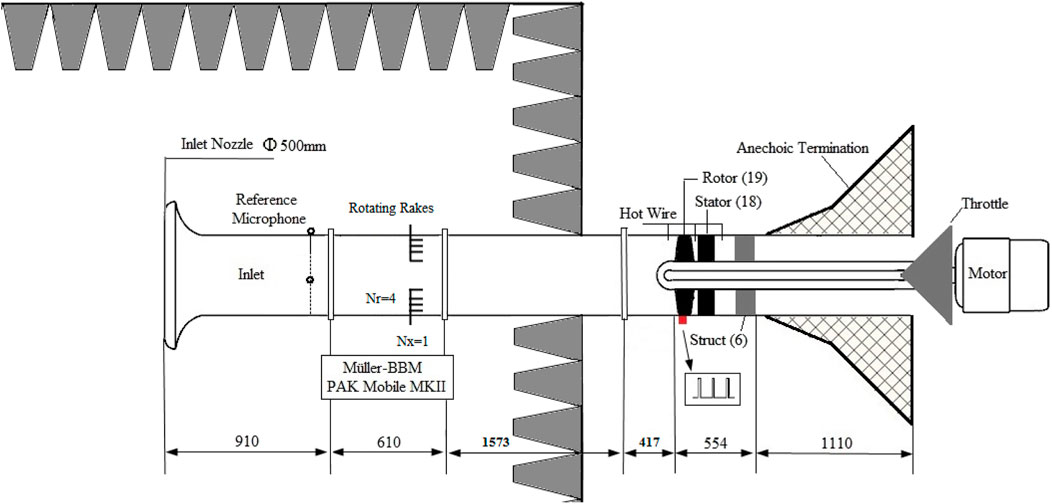
The experimental test scheme of the axial microphone array is shown in Figure 10. The acoustic measurement device is installed in the inlet section of the fan, 1.50 m away from the leading edge of the rotor blade tip. The entire acoustic measurement section and the fan inlet are placed in a semi-anechoic chamber. Four rows of microphones were installed on the acoustic measurement section with an axial spacing of 10 cm. Each row consists of 8 flush-mounted microphones with equal angles.
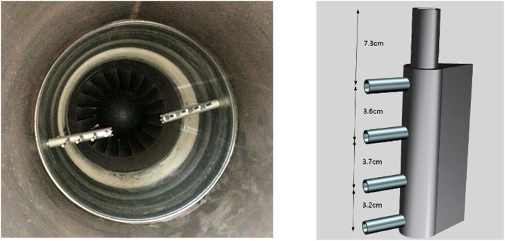
Radial rakes are designed and fabricated in this study in order to compare the influence of different microphone arrays on fan noise measurement. The radial rakes are also installed in the acoustic measurement section at the same location as the axial microphone array, and multi-angle measurement is achieved by installing the radial rakes on the casing that can rotate around the axis. A total of 60 circumferential positions are measured in the experimental test. As shown in Figure 11, two radial rakes are installed at the same axial position and separated by 180° in the circumferential direction. Figure 12 shows the actual photo and three-dimensional design of the radial rakes. Each rake has a total of
Applying radial rakes to the mode decomposition test of fan noise needs to pay attention to two issues: (1) since the measuring device penetrates deep into the cross section in the duct, it will inevitably affect the original flow field, and its wake may interfere with the rotor and then generate a new interference mode, which may eventually affect the original fan noise field and (2) the microphone is located inside the flow field, and the measured sound pressure will be affected by the airflow velocity and pressure pulsation, which thereby can reduce the signal-to-noise ratio in acoustic test.
This study adopts two ways to deal with the first issue: on one hand, the outer wall of the pipeline wrapping the signal line is designed to be streamlined, so as to ensure that the radial rake is not a blunt trailing edge structure; on the other hand, the axial position of the radial rake is nearly 2 m away from the rotor leading edge. According to the research of Chong (Chong et al., 2015), the turbulent intensity will decay approximately with a regularity
5.2 Signal-to-Noise Ratio
In order to analyze the accuracy of sound pressure acquisition data, the concept of signal-to-noise ratio (SNR) is used here, which can be defined as follows (Joseph et al., 2003; Tapken et al., 2008):
where
For a single sound pressure measurement point, starting from time
When repeated
It represents the predicted magnitude of random noise superimposed on the valid signal during the measurement.
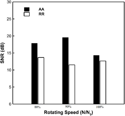
Figure 13 shows the signal-to-noise ratio results of the sound pressure data measured by the two arrays at different operation conditions. It can be seen that the SNR values at all operation conditions are higher than 10 dB, which indicates that the quality of the sound pressure data during the entire measurement process is good. The signal-to-noise ratio of the axial array increases as the rotational speed increases because the aerodynamic interference between the rotor and stator becomes stronger with higher rotational speed. However, the signal-to-noise ratio of the radial rakes decreases with increasing rotational speed; this may be because when the air velocity increases, the influence of the air pressure pulsation on the radial rake is also intensified. In order to further investigate this phenomenon, Figure 14A presents the RMS and
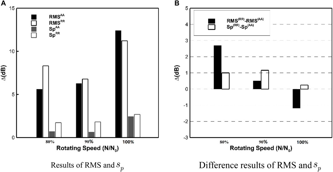
FIGURE 14. RMS and
5.3 Mode Decomposition Results
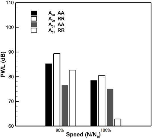
Based on the two measurement devices designed in the above sections, this section conducts experimental measurements on the fan inlet noise. Figure 15 presents the sound power results for each circumferential mode measured by the axial array (AA) and radial rake (RR) at 1 BPF. Figure 15A shows the results of circumferential sound power at 90% design speed condition. It can be seen that the modal sound power calculated by the radial rakes is generally larger than that of the axial arrays, the difference between the dominant mode m = 1 is 3 dB, and the difference between the non-dominant modes is even greater. It can be seen that the results measured by the two arrays are in good agreement on the whole at 100% design speed condition as shown in Figure 15B. The difference in the sound power results of the m = 1 dominant mode measured using the two devices is less than 1 dB, and the test results of the two devices are also in good agreement in the low-order circumferential mode range (m = −2 to m = +1). The sound power results of the high-order circumferential mode measured by different arrays have large deviations, which may be caused by the non-dominant modes being “buried” into random noise in the calculation. Referring to Figure 13, the SNR of the measured signal at 90% design speed condition is only 11 dB, but the non-dominant mode (m≠1) in Figure 15A is at least 13 dB lower than that of the dominant mode, and the difference is greater than the acquisition signal-to-noise ratio of the signal, which makes the estimation results of these non-dominant modes heavily influenced by random noise and eventually unreliable. At 100% design speed condition, although the signal-to-noise ratio of the two arrays is relatively small, the measurement results of the two devices have high consistency. In order to better investigate the influence of random noise during measurement on mode identification, it is necessary to derive the transfer relationship between the mode identification error and the random noise of sound pressure measurement. For the sound pressure measured at a single location, it can be expressed as a superposition of the actual value and random noise, namely,
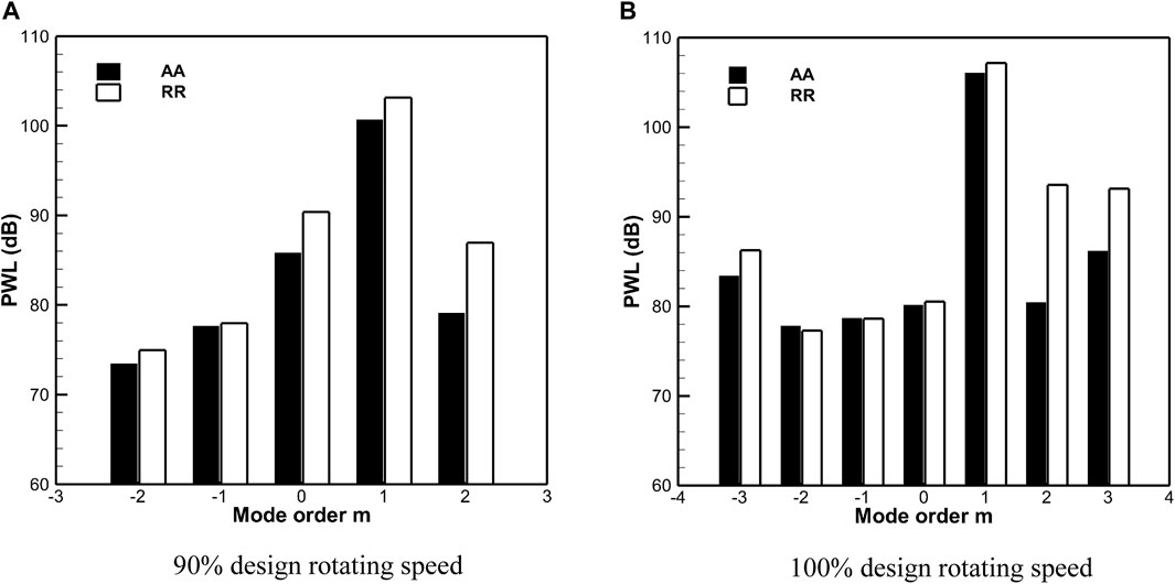
FIGURE 15. Comparison of modal sound power applying radial rakes and axial microphone arrays. (A) 90% design rotating speed. (B) 100% design rotating speed.
In the formula, the random noise amplitude satisfies the Gaussian distribution. If the random noise collected at different measuring points is incoherent, then the expected value of random noise satisfies the following:
If it is further assumed that all measuring points and the signal transfer function are the same, then the amplitude of the circumferential mode can be written as follows:
The first part of Eq. 19 is denoted as
Therefore, the standard deviation in mode identification is as follows:
That is to say, the standard deviation of mode identification is smaller than the standard deviation of sound pressure measurement, and the two values are proportional. This shows that random noise during measurement will have a linear effect on the accuracy of mode identification.
The modal acoustic powers calculated by the radial rakes in Figure 15 are generally greater than the results of the axial arrays because the random noise measured by the radial rake is larger than that of the axial array. As shown in Figure 14,
Although the mode decomposition results of different radial modes are different, this effect is negligible for circumferential mode recognition, for example, the sound power of the m = 0 mode measured by the two arrays matches very well as shown in Figure 15B. The above content mainly focuses on the influence of random noise in sound pressure measurement on modal recognition, but as Taddei et al. (2013) stated, the accuracy of the acoustic model used in mode decomposition is another main factor affecting mode identification. Distortion of the airflow in the duct, other noise sources, errors in the aerodynamic parameters of the airflow, etc. will affect the accuracy of the mode identification, and the two typical arrays have different sensitivities to the acoustic models used in the mode identification. This study uses an equally spaced axial array and radial rakes to test the fan noise. For non-equidistant or compressed sensing arrays, finding out whether the error transfer characteristics obtained in this study are applicable requires further research. How to use the obtained error characteristics in modal decomposition to design a new test method or a new array scheme needs further research, especially for large ventilation facilities.
6 Conclusion
Based on the error analysis theory, the influence of different microphone arrays on the accuracy of acoustic mode identification is studied, and the design criteria for axial microphone arrays are established. Through the processing of rotating radial rakes and axial arrays, the experimental analysis of the acoustic mode identification error applying different arrays is carried out.
Although radial rakes can directly measure the radial distribution of the modal amplitude, this type of array has a large error in the mode identification at low frequencies. As the frequency approaches the cut-on frequency of the mode, the condition number of the coefficient matrix increases by about two orders of magnitude. Compared with the axial arrays, the radial rakes are more suitable for mode identification at high frequencies. At low frequencies, the condition number of the coefficient matrix is less than 10 when applying axial arrays. Therefore, the axial microphone arrays will become more advantageous than the radial rakes in practice. The design criterion of axial microphone array is established: (a) m = 0 mode is the dominant mode that restricts the mode identification accuracy and the upper limit of the frequency that can be solved; (b) the accuracy of the axial microphone array in mode identification strongly depends on the axial spacing of the array measuring points, and when
The experimental test results show that the modal sound power values calculated with axial arrays and radial rakes are in good agreement, especially for the rotor–stator interference mode determination. The small deviations in the mode identification when applying the two typical arrays are caused by the different signal-to-noise ratios of the sound pressure signals acquired by the two arrays and their discriminative sensitivities to the duct airflow.
Data Availability Statement
The raw data supporting the conclusion of this article will be made available by the authors, without undue reservation.
Author Contributions
KX is responsible for the whole article, CL is responsible for the experimental investigation and also the data processing, FT is responsible for the error analysis, and WQ is responsible for the article scheme and the idea to investigate the difference of modal sound power when using the two typical arrays.
Funding
This work was financially supported by the National Natural Science Foundation of China (Grant No. 12002150), The Ministry of Education of Humanities and Social Science Project (Grant No. 20YJCZH196), the Natural Science Foundation of Jiangsu Province, China (Grant No. BK20201041), the Key Laboratory of Aerodynamic Noise Control of China Aerodynamics Research and Development Center (Grant No. ANCL20190306), and the Scientific Research Fund of High-Level Talents in Nanjing Institute of Technology (Grant No. YKJ201906).
Conflict of Interest
The authors declare that the research was conducted in the absence of any commercial or financial relationships that could be construed as a potential conflict of interest.
Publisher’s Note
All claims expressed in this article are solely those of the authors and do not necessarily represent those of their affiliated organizations, or those of the publisher, the editors, and the reviewers. Any product that may be evaluated in this article, or claim that may be made by its manufacturer, is not guaranteed or endorsed by the publisher.
References
Bolleter, U., Cohen, R., and Wang, J. (1973). Design Considerations for an In-Duct Soundpower Measuring System. J. Sound Vibration 28 (4), 669–685. doi:10.1016/s0022-460x(73)80142-7
Bolleter, U., and Crocker, M. J. (1972). Theory and Measurement of Modal Spectra in Hard‐Walled Cylindrical Ducts. The J. Acoust. Soc. America 51, 1439–1447. doi:10.1121/1.1912994
Cheng, L., Yang, W. K., and Liang, T. (2019). Failure Diagnosis on Gas Path of Fan/compressor Based on Acoustic Mode[J]. J. Mech. Eng. 55 (13), 38–44. doi:10.3901/JME.2019.13.038
Chong, T. P., Vathylakis, A., and Mcewen, A. (2015). “Aeroacoustic and Aerodynamic Performances of an Aerofoil Subjected to Sinusoidal Leading Edges [C],” in 21th AIAA/CEAS Aeroacoustics Conference. Dallas TX. AIAA 2015-2200.
Dahl, M. D., Hixon, R., and Sutliff, D. L. (2013). “Further Development of Rotating Rake Mode Measurement Data Analysis [C],” in 19th AIAA/CEAS Aeroacoustics Conference. AIAA-2013-2246.
Enghardt, L., Tapken, U., Kornow, O., and Kennepohl, F. (2005). “Acoustic Mode Decomposition of Compressor Noise under Consideration of Radial Flow Profiles[C],” in 11th AIAA/CEAS Aeroacoustics Conference, Monterey, United States, 2005–2833.
Enghardt, L., Tapken, U., Neise, W., Kennepohl, F., and Heing, K. (2001). “Turbine Blade/vane Interaction Noise: Acoustic Mode Analysis Using In-Duct Sensor Rakes[C],” in 7th AIAA/CEAS Aeroacoustics Conference. Maastricht, Netherlands, 2001–2153.
Enghardt, L., Tapken, U., Neise, W., Schimming, P., Maier, R., et al. (2002). Active Control of Fan Noise from High-Bypass Aeroengines: Experimental Results[J]. Aeronaut. J. R. Aeronaut. Soc. 106, 501–506. doi:10.1017/S0001924000092356
Enghardt, L., Zhang, Y., and Neise, W. “Experimental Verification of a Radial Mode Analysis Technique Using wall-flush Mounted Sensors[C],” in Joint Meeting”Berlin 99” TU-Berlin, March 1999, 137th Regular Meeting of the Acoustical Society of America.
Farassat, F., Nark, D. M., and Thomas, R. H. (2001). “The Detection of Radiated Modes from Ducted Fan Engines[C],” in 7th AIAA/CEAS Aeroacoustics Conference. Maastricht, Netherlands, 2001–2138.
Heidelberg, L., and Hall, D. G. (1996). Inlet Acoustic Mode Measurements Using a Continuously Rotating Rake [J]. AIAA J. Aircraft. 32 (4), 761–767. doi:10.2514/3.46788
Holste, F., and Neise, W. (1997). Noise Source Identification in a Propfan Model by Means of Acoustical Near Field Measurements. J. Sound Vibration 203 (4), 641–665. doi:10.1006/jsvi.1996.0890
Joppa, P. D. (1987). Acoustic Mode Measurements in the Inlet of a Turbofan Engine. J. Aircraft 24 (9), 587–593. doi:10.2514/3.45482
Joseph, P., Morfey, C. L., and Lowis, C. R. (2003). Multi-mode Sound Transmission in Ducts with Flow. J. Sound Vibration 264 (3), 523–544. doi:10.1016/s0022-460x(02)01205-1
Kan, K., Yang, Z., and Lyu, P. (2021). Numerical Study of Turbulent Flow Past a Rotating Axial-Flow Pump Based on a Level-Set Immersed Boundary Method[J]. Renew. Energ. 168, 960–971. doi:10.1016/j.renene.2020.12.103
Kim, Y., and Nelson, P. A. (2004). Estimation of Acoustic Source Strength within a Cylindrical Duct by Inverse Methods [J]. J. Sound Vibration 275 (1-2), 391. doi:10.1016/j.jsv.2003.06.032
Lan, J. H., Premo, J. W., and Sutliff, D. L. (2002). “Inlet Mode Measurements with an Inflow Control Device Microphone Array[C],” in 8th AIAA/CEAS Aeroacoustics Conference, Breckenridge, United States, 2002–2563.
Liu, J., Liu, Y., and Bolton, J. S. (2018). Acoustic Source Reconstruction and Visualization Based on Acoustic Radiation Modes. J. Sound Vibration 437, 358–372. doi:10.1016/j.jsv.2018.08.030
Moore, C. J. (1979). Measurement of Radial and Circumferential Modes in Annular and Circular Fan Ducts. J. Sound Vibration 62 (2), 235–256. doi:10.1016/0022-460x(79)90024-5
Nelson, P., and Yoon, S. (2000). Estimation of Acoustic Source Strength by Inverse Method: Part I, Conditioning of the Inverse Problem [J]. J. Sound Vibration 233 (4), 643–668. doi:10.1006/jsvi.1999.2837
Qiao, W. Y. (2010). Aero-engine Aeroacoustics [M]. Beijing: Beijing University of Aeroacoustics & Astronautics Press, 1–8.
Sutliff, D. L. (2005). Rotating Turbofan Duct Mode Measurement system[R]. NASA-TM-213828. Cleveland, OH: Glenn Research Center.
Taddei, F., Lucia, M. D., Torzo, D., and Spano, E. (2013). “A Comparison between Radial Rakes of Sensors and Axial Arrays of Microphones for the Experimental Investigation of Tone Noise in LPTs [C],” in 19th AIAA/CEAS Aeroacoustics Conference. Berlin.
Tapken, U., Bauers, R., and Enghardt, L. (2008). “Turbomachinery Exhaust Noise Radiation Experiments-Part 2: In-Duct and Far-Field Mode Analysis [C],” in 14th AIAA/CEAS Aeroacoustics Conference (Vancouver, British Columbia Canada. AIAA-2008-2858.
Tapken, U., and Enghardt, L. (2006). “Optimization of Sensor Arrays for Radial Mode Analysis in Flow Ducts[C],” in 12th AIAA/CEAS Aeroacoustics Conference (Cambridge, MA. UK, 2006–2638.
Tapken, U., Raitor, T., and Enghardt, L. (2009). “Tonal Noise Radiation from an UHBR Fan- Optimized In-Duct Radial Mode Analysis[C],” in 15th AIAA/CEAS Aeroacoustics Conference. AIAA-2009-3288.
Wagih Nashed, M., Elnady, T., and Åbom, M. (2018). Modeling of Duct Acoustics in the High Frequency Range Using Two-Ports. Appl. Acoust. 135, 37–47. doi:10.1016/j.apacoust.2018.01.009
Wang, L. F., Qiao, W. Y., and Ji, L. (2014). In-duct Circumferential Acoustic Mode Measurement of Axial fan/Compressor[J]. J. Aerospace Power 29 (4), 917–926. doi:10.13224/j.cnki.jasp.2014.04.024
Xu, K. B., Qiao, W. Y., and Huo, S. Y. (2018). Research of Mode Identification and Error Transfer Property on Fan Tonal Noise [J]. J. Propulsion Technology 39 (1), 185–195. doi:10.13675/j.cnki.tjjs.2018.01.021
Yardley, P. D. (1974). Measurement of Noise and Turbulence Generated by Rotating Machinery [D]. PhD Thesis. Southampton: University of Southampton.
Zhou, D., Wang, X. Y., and Chen, J. (2015). Investigation of Sound Generation by Non-synchronously Vibrating Rotor Blades[J]. Acta Aeronautica et Astronautica Sinica 36 (3), 737–748. doi:10.7527/S1000-6893.2015.0029
Keywords: fan noise, error character, modal decomposition, microphone array, signal-to-noise (S/N) ratio
Citation: Xu K, Liu C, Tong F and Qiao W (2022) Numerical and Experimental Study on Mode Identification Error Characteristics of Fan Noise. Front. Energy Res. 10:875638. doi: 10.3389/fenrg.2022.875638
Received: 14 February 2022; Accepted: 03 March 2022;
Published: 22 March 2022.
Edited by:
Kan Kan, College of Energy and Electrical Engineering, ChinaReviewed by:
Qiang Fu, Xi’an Aeronautical University, ChinaYanhua Wang, Harbin Engineering University, China
Qiang Gao, University of Minnesota Twin Cities, United States
Copyright © 2022 Xu, Liu, Tong and Qiao. This is an open-access article distributed under the terms of the Creative Commons Attribution License (CC BY). The use, distribution or reproduction in other forums is permitted, provided the original author(s) and the copyright owner(s) are credited and that the original publication in this journal is cited, in accordance with accepted academic practice. No use, distribution or reproduction is permitted which does not comply with these terms.
*Correspondence: Kunbo Xu, eHVrdW5ib0Buaml0LmVkdS5jbg==
 Kunbo Xu
 Cunliang Liu1