- 1Key Laboratory of Fluid Transmission Technology of Zhejiang Province, Zhejiang Sci-Tech University, Hangzhou, China
- 2Department of Application and Engineering, Zhejiang Economic and Trade Polytechnical, Hangzhou, China
This study performed external characteristics, dynamic pressure, and vibration tests on the closed impeller model, semi-open type impeller model, and open impeller model in order to study the influence of the impeller structure on the operational stability of the pump. According to the research findings, the external characteristics of the three impellers enjoyed favorable stability with flat curves under low flow rates. As the flow increases, the stability of the external characteristics weakens, and the poorest stability can be observed in the open impeller, while the enclosed impeller has the best stability under a large flow rate. In addition, intense pressure fluctuations arise near the casing tongue due to the dynamic and static interference between the blade and the casing tongue, causing a large amplitude of pressure pulsation near the casing tongue and the pump outlet. It can be seen that the stability of pressure pulsation of the closed impeller in the casing tongue area was the best, whereas the stability of pressure pulsation of the open impeller was the poorest. The minimum casing vibration can be found in the closed impeller, followed by the semi-open impeller, and the open impeller, with the maximum vibration. In addition, the optimum stability of rotor vibration can be observed in the closed impeller, semi-open impeller, and open impeller with similar stability of rotor vibration.
Introduction
The centrifugal pump should be of high security and reliability during operation; otherwise, it might affect the normal operation. Hence, the stability of the operating condition of the centrifugal pumps has become a hotspot issue of high concern. Centrifugal pumps are widely used in the oil and gas industry (Bellary and Samad, 2016), aerospace engineering (Hong et al., 2013), marine engineering (Wang. et al., 2020), and other fields. Centrifugal pumps, in general, are equipped with varying types of impellers for different pumped mediums. An open impeller is suitable for conveying materials containing a large amount of suspended matter, a semi-open impeller is suitable for conveying easy precipitation or containing particles of material, and a closed impeller is suitable for conveying clean liquid without impurities (Gulich, 2010). Different impeller types have significant impacts on the operational stability and reliability of the centrifugal pump, mainly stable performance and vibration stability of the pump. To be specific, the stable performance of the pump involves a flat lift curve and equally distributed pressure, while vibration stability consists of satisfactory vibration characteristics of the rotor system and casing vibration characteristics. Stable operation of the centrifugal pump is normally affected by many complex flows in the operation of centrifugal pumps, such as interstitial flow (Wood et al., 1965), secondary flow (Klaus and Rainer, 2005), eddy current (Zhu and Kamemoto., 2005), and backflow (Yamamoto and Tsujimoto, 2009), as well as a variety of unstable phenomena occurring in the operation, such as rotating stall (Sano et al., 2002), rotor-stator interaction (Zheng et al., 2016), cavitation (Zhang et al., 2015), and vibration (Jia et al., 2015). Chen et al. (2022a) utilized a TR-PIV system to measure the flow fields in a special voluteless centrifugal pump. The contributions to the overall energy and the spatial/temporal behavior of the large-scale flow structures were analyzed in detail, and the dynamic and kinematic energy characteristics of the coherent flow structures that were in the impeller were revealed. Chen et al. (2022b) explored a method to directly describe the loss distribution trend of the flow field through the PIV experiment. Results show the distribution of local pressure head increase (Hpr) is affected mainly by the inlet flow field of the impeller passage, while the maximum value region of local velocity head increase (Hvr) along the radial direction is located at the downstream of the unstable region on the blade suction side and at the center of the unstable region on the pressure side. A vast number of numerical and experimental studies have been performed on the pressure pulsation and vibration characteristics of centrifugal pumps under unsteady conditions. He (1996) studied the mechanism of pressure pulsation of the pump and indicated that vibration and noise of the pump are related to the pressure pulsation of the pump. Pressure pulsation mainly consists of axial frequency and blade frequency pressure pulsations. Yuan et al. (2010) pointed out that no evident high-frequency component was found in the pressure pulsation of the volute under design flow rate. The dominant frequency at the same monitoring point was constant, but its amplitude varied under different flow rates. Specifically, the amplitude was large under low flow rate, reaching the minimum under design flow rate, according to Zhu and Hu (2010). Moreover, the centrifugal pump is also affected by the rotor–stator interaction and unsteady internal flow apart from the abovementioned influence of different hydraulic conditions on pressure pulsation, since asymmetry of pressure distribution and pressure pulsation are inevitable. Jia et al. (2019) studied the pressure distributions of the volute and the front sleeving wall under different flow rates, with the results showing that the asymmetry of the pressure distribution and the magnitude of the pressure decrease with the rising flow rate. The rotor–stator interaction between the rotating impeller and the fixed volute might lead to high-frequency unsteady pulsation inside the volute and low-frequency unsteady pressure pulsation inside the impeller. Yang et al. (2014) studied the influence of radial clearance between the blade tip of the impeller and the casing tongue on the performance and pressure pulsation of the pump as a turbine, showing that the high-frequency unsteady amplitude will be increased and the pressure pulsation in the volute will be decreased with the increase in radial clearance. Cui et al. (2015) studied the unsteady flow characteristics of the low specific speed centrifugal pump under varied flow rates, indicating that the flow instability resulted from the interaction of the impeller and the volute, thereby leading to the instability in the circumferential direction. As the impeller and the volute are essential for the generation of pressure pulsation inside the pump, their geometric parameters were modified in some studies to lower the pressure pulsation and vibration. Zhu et al. (2007) proved that the geometrical shape of the impeller blades exerted an impact on the unstable pressure pulsation. Tao et al. (2016) studied the effect of blade thickness on the transient flow characteristics of a centrifugal slurry pump with semi-open impellers. According to the result, the greater the blade thickness, the larger the pressure pulsation at the impeller outlet. This article studied closed, semi-open, and open impellers through performing external characteristics, dynamic pressure, and vibration characteristics tests under full flow rates, as well as comparatively analyzed the external characteristics, pressure pulsation, and vibration characteristics of the three impellers.
To sum up, most of the current centrifugal pump impeller structures are for a single type, and comparing the flow characteristics of different types of centrifugal pump impeller is impossible. Therefore, studying the influence of different impellers structures on the stability and reliability of centrifugal pumps is very important. In this article, the performance stability and vibration stability of centrifugal pumps with three typical impeller models (closed, semi-open, and open) are studied through external characteristic tests, dynamic pressure tests, and vibration tests.
Experimental Apparatus
The test bench designed for the operational stability of the centrifugal pump described in this study is composed of data acquisition systems, such as dynamic pressure, vibration characteristics, and external characteristics, as well as centrifugal pump, water tank, high-precision electromagnetic flowmeter, valves, water inlet and outlet pipelines, and motors. The circuits of the test system are shown in Figure 1A. A low specific speed centrifugal pump with three impeller types at a rotational speed of 3,000 r/min was tested. Specific performance parameters and geometric parameters are shown in Table 1. The physical diagram of the model centrifugal pump test bench is demonstrated in Figure 1B, and the physical diagrams of the three impellers of the model pump are presented in Figure 1C. Note that three impellers with the same molded lines have six blades. Clearwater is used as the experimental medium in this study.
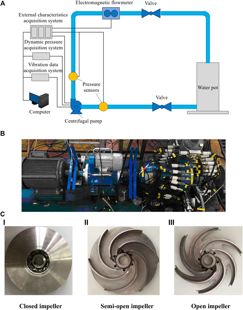
FIGURE 1. Experimental apparatus: (A) testing system of the centrifugal pump and (B) testing centrifugal pump (b): (Ⅰ) closed impeller, (Ⅱ) semi-open impeller, and (Ⅲ) open impeller (C) Testing centrifugal impellers.
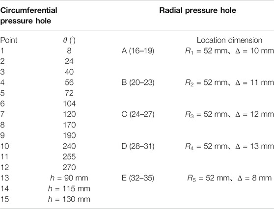
The centrifugal pump dynamic pressure test system is composed of a pump, pressure sensor, and dynamic pressure data acquisition system. The locations of pressure measuring points of the centrifugal pump body are given in Figure 2 and Table 2.
(The layout of monitoring points should reflect the pressure value of the centrifugal pump and its changing trend as far as possible. Therefore, on the premise of ensuring that effective data can be obtained, monitoring points should be arranged as much as possible in key positions with large pressure changes in order to ensure the performance stability of the centrifugal pump to make accurate judgment. This explains why the pressure testing points are not symmetrical on the casing. Due to the large unstable flow in the impeller runner, tongue area, and pump outlet, the monitoring points in these locations are properly encrypted, so as to more accurately reflect the pressure change of the centrifugal pump.)
The centrifugal pump vibration test system comprised an acceleration sensor, an eddy current displacement sensor, and a data acquisition system. The acceleration sensor is a piezoelectric triaxial acceleration sensor that can simultaneously measure the vibration acceleration in the directions of x, y, and z, with a sensitivity of 10 mV/g, a measuring range of 500 g, and a response frequency ranging from 0.5 to 10 kHz. Acceleration sensors are installed at the pump inlet, pump outlet, casing tongue area, and pump body. As can be seen from the installation position of the acceleration sensor in Figure 3, measuring point 1 is installed at the position near the volute tongue, measuring point 2 is installed on the pump outlet flange, measuring point 3 is installed on the pump body, and measuring point 4 is installed on the inlet flange. The sensitivity of the eddy current vibration displacement sensor used is 4 mV/μm, with the effective measuring distance ranging from 0 to 2 mm, and the frequency response ranging from 0 to 10 kHz. The installed position of the eddy current vibration displacement sensor is shown in Figure 3, with the horizontal direction defined as direction x and the vertical direction as direction y.
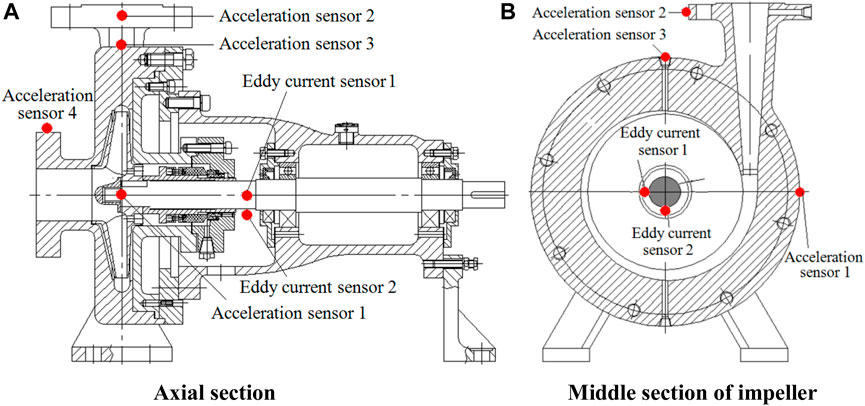
FIGURE 3. Install locations of acceleration sensors and eddy current sensors: (A) axial section and (B) middle section of impeller.
External characteristics, pressure pulsation, and vibration data are collected synchronously via 64-channel data collectors with a maximum sampling frequency of 204.8 kHz. Sampling can be performed by each channel in a simultaneous and parallel manner with an amplitude accuracy of 0.1% FS (1 V input, ≤10 kHz) and a frequency accuracy of 0.001%.
Results and Discussion
External Characteristics
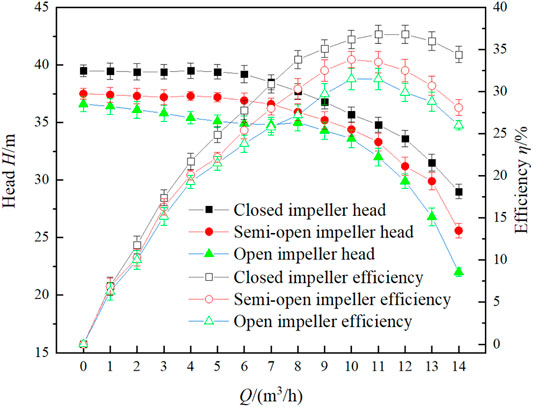
External characteristic curves of the three impeller model pumps under full flow rates are presented in Figure 4. Evidently, the closed impeller has the highest lift and efficiency, whereas the open impeller has the smallest lift and efficiency. The lift curves of the three impellers are relatively stable and flat at small flow rates. When the flow rate increased from 1.0Qdes to 1.4Qdes, the lifts of the three impellers dropped significantly. Specifically, the lifts of the closed impeller, the semi-open impeller, and the open impeller were dropped by 19.05%, 29.86%, and 38.95%, respectively. Evidently, the lifts of the three impellers are relatively stable under small flow rates, which become less stable with rising flow rates. In addition, the closed impeller has the best lift stability, while the open impeller has the worst lift stability.
Circumferential pressure distribution profiles of the three impeller volute walls under different flow rates are shown in Figure 5. Apparently, the pressures of the three impellers are progressively decreased with the increasing flow rate as the strengthening degree of pressure declines. The pressure change of the closed impeller is less affected by the flow rate, followed by the semi-open impeller, and the wall pressure of the volute of the open impeller is most sensitive to flow change. The pressure drop of the closed impeller near the pump outlet is smaller than that of the other two impellers with the rising flow rate, and the open impeller has the most obvious pressure drop.

FIGURE 5. Static pressure on volute casing of the centrifugal pump with three impellers: (A) closed impeller, (B) semi-open impeller, and (C) open impeller.
When the flow rate is small (ranging from 0 to 0.8Qdes), the pressure will be increased from the circumferential position of 0° to the pump outlet, and the maximum will be reached at the impeller outlet. The pressure increase gradient is increased near the casing tongue of the volute, and the pressure increase trend becomes more significant with the rising flow rate. The pressure increase near the volute reaches 40 kPa at 0–0.4Qdes, while the pressure increase is only 10 kPa at 0.8Qdes for the closed impeller. The pressure increase trend becomes gentle from the volute tongue to the pump outlet, and the pressure increase for the open impeller reaches only 15 kPa. When the flow rate is large, the pressure at the casing tongue of the volute will suddenly decrease, and the pressure drop range will become more severe with the further increasing flow rate with the pressure drop gradient reaching its maximum at 1.4Qdes. The closed impeller, semi-open impeller, and open impeller reached the maximum pressure drop amplitudes of 39 kPa, 45 kPa, and 51 kPa, respectively, at the separation tongue, and the pressure is rising quickly from the casing tongue of the volute to the pump outlet, with their pressure rise amplitudes reaching 60 kPa, 46 kPa, and 25 kPa, respectively. This showed that the closed impeller has the strongest pressure recovery capability with good pressure distribution stability, while the open impeller has the weakest pressure recovery capability with the worst pressure distribution stability at large flow rates from the volute tongue to the pump outlet.
Radial static pressure distribution profiles of the three impeller front cover walls under different flow rates are shown in Figure 6. As can be observed from the figure, the closed impeller has the largest pressure value, followed by the semi-open impeller, and the open impeller has the smallest pressure value. The pressure is on the rise along the direction from the impeller inlet to the outlet. The maximum pressure increase gradient is found in group D, and then pressure drops rapidly in group E. The closed impeller has the smallest degree of pressure drop in group E, followed by the semi-open impeller, and the open impeller has the greatest degree of pressure drop. As group E is located near the volute tongue area, the quick drop in static pressure might lead to a sharp increase in the fluid speed of the tongue area. As a consequence, energy loss caused by the collision between fluids as well as between fluid and wall might increase, conveying slanted against fluids. This shows that the stable pressure distribution of the closed impeller in the tongue area is most conducive to fluid conveying, whereas the excessive pressure drop of the open impeller in the tongue area is least conducive to fluid conveying.

FIGURE 6. Static pressure on front casing of the centrifugal pump with three impellers: (A) closed impeller, (B) semi-open impeller, and (C) open impeller.
Pressure Pulsation Characteristic
Pressure fluctuation distribution profiles of the three impeller volute walls under design flow rates in the frequency domain are shown in Figure 7. Apparently, the axial frequency and the blade frequency of the closed impeller test are 49.85 Hz and 298.16 Hz, respectively; the axial frequency and the blade frequency of the semi-open impeller test are 49.79 Hz and 298.03 Hz, respectively; and the axial frequency and the blade frequency of the open impeller test are 49.73 Hz and 297.52 Hz, respectively. As can be observed from Figure 9, the degree of pressure pulsation is strengthened along the rotating direction of the impeller from the pressure measuring point 1 to 15, reaching the maximum at the pump outlet. The dominant frequency of pressure pulsation is concentrated at the shaft frequency at measuring points 1 to 12, while the dominant frequency of pressure pulsation is concentrated at the blade frequency at the pressure measuring points (measuring points 13–15) of the pump outlet. A frequency range of broadband pulsation exists at all pressure measuring points. So the position of the broadband pulsation moves gradually from near the shaft frequency to near the blade frequency from measuring points 1 to 15. The broadband pulsation is concentrated at the blade frequency or above at the pump outlet. The open impeller has the largest pressure pulsation amplitude, and conversely, the closed impeller has the smallest amplitude at the same measuring point. In the model pump, pressure pulsation at varying positions in the volute has different effects on the operational stability of the pump; the effect degree gradually increases from the starting point of the volute spiral to the outlet along the rotation direction, and the operational stability of the pump is dependent on pressure pulsations at the pump outlet and the casing tongue of the volute.

FIGURE 7. Pressure pulsations on volute casing of three impellers at design point: (A) closed impeller, (B) semi-open impeller, and (C) open impeller.
Pressure fluctuation distribution profiles of the three impeller volute walls under design flow rates in the frequency domain are shown in Figure 8. Apparently, the axial frequency and the blade frequency of the closed impeller test are 49.85 Hz and 298.16 Hz, respectively; the axial frequency and the blade frequency of the semi-open impeller test are 49.79 Hz and 298.03 Hz, respectively; and the axial frequency and the blade frequency of the open impeller test are 49.73 Hz and 297.52 Hz, respectively. As can be observed from Figure 8, the maximum pressure pulsation amplitude appeared in group D, and the maximum pressure pulsation of the closed impeller was the smallest in group D, followed by the open-plate impeller, and the open-type impeller was the largest. The amplitude of pressure pulsation in group E is small. Because group E is close to the tongue region, pressure pulsation here will cause a large energy loss. In the model pump, the effect degree on the operational stability of the pump gradually increases from the inlet of the impeller to the outlet.

FIGURE 8. Pressure pulsations on volute casing of three impellers at design point: (A) closed impeller, (B) semi-open impeller, and (C) open impeller.
To obtain the relationship between the pressure pulsation intensity and the flow rate at different circumferential positions of the volute in a rotation cycle, the dimensionless coefficient of the event-related pressure pulsation intensity is defined as Cpsd, which can be expressed as
where N is the number of time steps in a stable rotation cycle (it is 360 in this paper), p(x, y, z, ti) is the static pressure value of the node (x, y, z) at the ith time step, ρ is the fluid density, and u2 is the peripheral speed of the impeller outlet.
The pressure pulsation intensity at monitoring points 1–15 of the three impellers under design flow rate is presented in Figure 9. Pressure pulsation amplitudes at measuring points 1 to 11 fluctuate gently for the three impeller types. Pressure pulsation amplitudes near the casing tongue (at the measuring point 12) and the pump outlet (at the measuring 13 to the measuring 15) are significantly greater than those of other measuring points, and the pulsation amplitudes of the open impeller and the semi-open impeller are 7.7% and 3.5% greater than those of the closed impeller, respectively. The open impeller has the largest pressure pulsation amplitude, while the closed impeller has the smallest amplitude at the same measuring point. It indicates that intense pressure fluctuations arise near the casing tongue due to the dynamic and static interference between the blade and the casing tongue, causing a large amplitude of pressure pulsation near the casing tongue and the pump outlet. At the same time, the closed impeller has the best stability under pressure pulsation and the open impeller has the poorest stability under pressure pulsation.
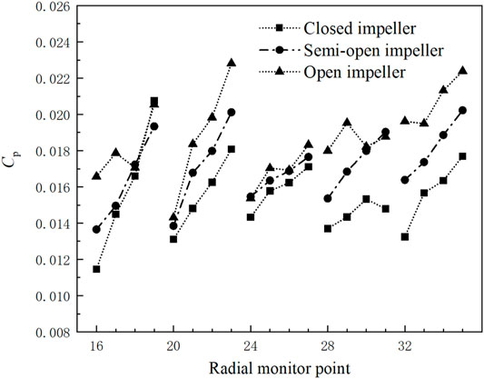
The pressure pulsation intensity at monitoring points 16–35 of the three impellers under design flow rate is presented in Figure 10. The pressure pulsation intensity increases gradually along the direction from the impeller inlet to the impeller outlet, and reaches its maximum at the impeller outlet. As group E is located near the volute tongue area, the static pressure drops rapidly here, so the pressure pulsation intensity is greater than that in other positions.
Vibration Characteristics
The distribution profile of vibration acceleration in domain frequency at the casing tongue of the volute of varying impellers under design flow rates is shown in Figure 11. According to Figure 5, the dominant frequency of vibration acceleration is at the shaft frequency only when the motor is rotating. At the same time, certain vibration acceleration pulsations can be found at the multiplier of the shaft frequency. Moreover, a certain degree of vibration can also be observed at the shaft frequency and its multiplier when the pump is idling. The dominant frequencies of vibration acceleration of the centrifugal pumps with three impeller types are the blade frequencies, with distinct pulsation amplitudes at the shaft frequency and its multiplier. Among them, the open impeller has the maximum pulsation of vibration acceleration, followed by the semi-open impeller, and the closed impeller has the smallest acceleration pulsating amplitude. The maximum vibration acceleration pulsation amplitudes of the open, semi-open, and closed impellers at the blade frequency are 0.046 m/s2, 0.039 m/s2, and 0.035 m/s2, respectively, with 0.026 m/s2, 0.025 m/s2, and 0.015 m/s2, respectively, at the shaft frequency. It can be seen that vibration acceleration in the tongue area is larger than that in other areas, demonstrating that internal flow in the area is unstable. The dynamic and static interference between the impeller in the pump and the casing tongue has the maximum impact on the vibration of the pump case. Comparatively speaking, the flow in the casing tongue area of the closed impeller is more stable than that of the other two impellers.
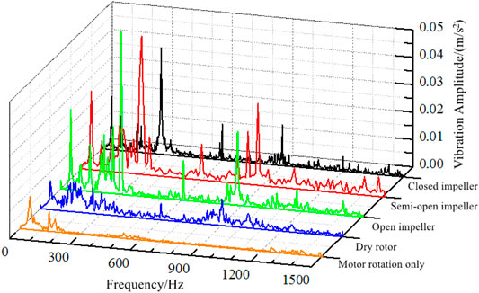
FIGURE 11. Frequency distribution of vibrating acceleration of different impellers at design flow rate.
The distribution profile of radical vibration displacement of the pump shaft of the centrifugal pump with different impeller types under design flow rates in a rotation cycle is shown in Figure 12. Vibration displacements in the x and y directions share similar distribution patterns, with a phase difference of 90°. Displacement components of the rotating shaft in the x and y directions fluctuate slightly, from−0.008 mm to 0.012 mm when the motor is idling. Evidently, the model pump motor shaft has favorable dynamic balance performance. When the pump is idling, the model pump shaft fluctuates from−0.025 mm to 0.045 mm in direction x, and from−0.041 mm to 0.028 mm in direction y. It can be seen that a certain range of shaft vibration displacement deviation can be witnessed between the model pump shaft and the motor shaft due to rotor centering. As a result, the vibration displacement when the pump is idling is greater than that when the motor is idling. Components of vibration displacement in the x and y directions have similar distribution patterns for three impellers. The rotation center of the closed impeller rotor system is much closer to that when the pump is idling, and both are closer to the shaft center. On the contrary, the rotation centers of the centrifugal pumps with semi-open and open impellers greatly deviate from the shaft center. In combination with Figure 5, it can be found that the circumferential pressure of the volute of the closed impeller is uniformly distributed, showing a slowly rising trend; and the circumferential pressures of the volutes of the open impeller and semi-open impeller are dropping suddenly near the casing tongue, which might be caused by the shape of the decline in the fluid force acting on the impeller in the area. Furthermore, it leads to the shifted center of rotation of the pump shaft.
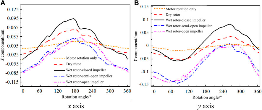
FIGURE 12. Vibration displacements of different impellers at design flow rate: (A) x axis and (B) y axis.
The distribution profile of radical vibration displacement of the pump shaft of the centrifugal pump with different impeller types under design flow rates in the frequency domain is shown in Figure 13. Evidently, the dominant frequency of pulsation of vibration displacement of the model pump in the x and y direction components is at the shaft frequency when the motor and pump are idling, and the pulsating amplitude of vibration displacement at the dominant frequency when the pump is idling is greater than that when the motor is idling. The pulsating amplitude of idling vibration displacement at the dominant frequency is roughly 0.013 mm, whereas the pulsating amplitude of vibration displacement when the motor is idling is only 0.004 mm. The dominant frequencies of vibration displacement pulsation for three impeller types are at the shaft frequency, with the pulsation amplitude far greater than that of the idled pump. Therefore, the excitation force of the unsteady fluid in the pump has a remarkable impact on the vibration of the pump rotor system. Meanwhile, the pulsating amplitude of the closed impeller at the dominant frequency is smaller than that of the other two impellers, and the open impeller has the maximum pulsating amplitude. According to the research on rotor vibration of varying impeller types, the closed impeller rotor system has the optimum vibration stability, and the semi-open and open impellers have similar rotor vibration stability. In addition, pressure pulsation and fluid exciting force are dominant factors affecting the vibration stability of the pump rotor. Furthermore, the rotor vibration stability is less affected by the motor vibration, and more affected by the rotor centering problem between the pump and the motor.
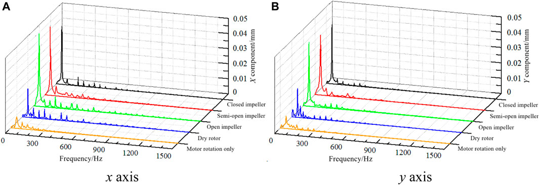
FIGURE 13. Frequency distribution of vibration displacements of different impellers: (A) x axis and (B) y axis.
Simonovskiy et al. (2021) introduced the method of linear and nonlinear parameter identification for vibration mathematical models of centrifugal pumps and turbocharger rotors to ensure vibration reliability of the centrifuge rotor system. As an example of using the proposed methodology, the analysis of forced oscillations and stability of the rotor’s rotation of a centrifugal compressor for underground gas storage with 25 MW power is considered. In solving the nonlinear differential equations, the time characteristics, the spectrum, and the orbit of rotor oscillations for 2nd mass in the directions of the X-axis and Y-axis in the case of stable and unstable rotation are obtained. The vibration results obtained in my experiment have similar distribution patterns. The vibration displacement of the rotor system in the X-axis and Y-axis directions is periodic. In the same period, the deviation degree between the rotation center and the axis center is also different at different times. The reliability of my test results has been verified.
Conclusion
This study analyzed the lift and efficiency, the circumferential pressure distribution of the volute wall, the dynamic pressure of the volute wall and the front cover wall, the vibration acceleration, the radial vibration displacement of the pump shaft, and the vibration energy for model pumps with three varying impellers under different flow rates. Conclusions are presented as follows:
1) The closed impeller enjoys the best performance stability, whereas the open impeller has the poorest performance stability, particularly when the flow rate is large. The closed impeller has the maximum radial static pressure value of the front cover wall, followed by the semi-open impeller, and the open impeller shows the least static pressure value. The stable pressure distribution of the closed impeller in the casing tongue area is most favorable to fluid conveying, whereas the excessive pressure drop in the casing tongue area of the open impeller is least conducive to fluid conveying.
2) In the model pump, pressure pulsation at varying positions in the volute has different effect degrees on the operational stability of the pump; the effect degree gradually increases from the starting point of the volute spiral to the outlet along the rotation direction. Also, intense pressure fluctuations arise near the casing tongue due to the dynamic and static interference between the blade and the casing tongue, causing a large amplitude of pressure pulsation near the casing tongue and the pump outlet. The pulsation amplitudes near the casing tongue of the open impeller and the semi-open impeller are 7.7% and 3.5% greater than those of the closed impeller, respectively. At the same time, the closed impeller has the best stability under pressure pulsation and the open impeller has the poorest stability under pressure pulsation.
3) Based on the findings of vibration acceleration, tongue vibration has the greatest proportion, and the flow in the volute tongue area is the least stable among the vibrations of the pump case. The maximum vibration acceleration pulsation amplitudes of the open, semi-open, and closed impellers at the blade frequency are 0.046 m/s2, 0.039 m/s2, and 0.035 m/s2, respectively, with 0.026 m/s2, 0.025 m/s2, and 0.015 m/s2, respectively, at the shaft frequency. The minimum casing vibration can be found in the closed impeller, followed by the semi-open impeller, and the open impeller has the maximum vibration. The optimum stability of rotor vibration can be observed in the closed impeller, semi-open impeller, and open impeller with similar stability of rotor vibration.
Overall, it can be proven that the centrifugal pump equipped with a closed impeller has the best performance stability and vibration stability, followed by the semi-open impeller, and the open impeller is the worst.
Data Availability Statement
The raw data supporting the conclusions of this article will be made available by the authors, without undue reservation.
Author Contributions
XJ: conceptualization, methodology, investigation, writing—original draft, writing—review and editing. QC: formal analysis and data curation. LZ: investigation. ZZ: validation.
Funding
This work was supported by the National Natural Science Foundation of China (Grant No. 51906221) and the Joint Fund of the Zhejiang Natural Science Foundation (Grant No. LZY21E060002).
Conflict of Interest
The authors declare that the research was conducted in the absence of any commercial or financial relationships that could be construed as a potential conflict of interest.
Publisher’s Note
All claims expressed in this article are solely those of the authors and do not necessarily represent those of their affiliated organizations, or those of the publisher, the editors, and the reviewers. Any product that may be evaluated in this article, or claim that may be made by its manufacturer, is not guaranteed or endorsed by the publisher.
References
Bellary, S. A. I., and Samad, A. (2016). Pumping Crude Oil by Centrifugal Impeller Having Different Blade Angles and Surface Roughness. J. Petrol. Explor Prod. Technol. 6, 117–127. doi:10.1007/s13202-015-0173-y
Chen, B., Li, X., and Zhu, Z. (2022). Investigations of Energy Distribution and Loss Characterization in a Centrifugal Impeller through PIV experiment. Ocean Eng. 247 (2022), 110773. doi:10.1016/j.oceaneng.2022.110773
Chen, B., Li, X., and Zhu, Z. (2022). Time-Resolved Particle Image Velocimetry Measurements and Proper Orthogonal Decomposition Analysis of Unsteady Flow in a Centrifugal Impeller Passage. Front. Energ. Res. 9, 818232. doi:10.3389/fenrg.2021.818232
Cui, B., Chen, D., Xu, W., Jin, Y., and Zhu, Z. (2015). Unsteady Flow Characteristic of Low-Specific-Speed Centrifugal Pump under Different Flow-Rate Conditions. J. Therm. Sci. 24 (1), 17–23. doi:10.1007/s11630-015-0750-x
He, X. (1996). The Mechanism on Forming of the Pressure Pulse in Vane Pump. Mech. Sci. Technol. Aerosp Eng. 25 (6), 38–42.
Hong, S.-S., Kim, D.-J., Kim, J.-S., Choi, C.-H., and Kim, J. (2013). Study on Inducer and Impeller of a Centrifugal Pump for a Rocket Engine Turbopump. Proc. Inst. Mech. Eng. C: J. Mech. Eng. Sci. 227, 311–319. doi:10.1177/0954406212449939
Jia, X.-Q., Cui, B.-L., Zhang, Y.-L., and Zhu, Z.-C. (2015). Study on Internal Flow and External Performance of a Semi-open Impeller Centrifugal Pump with Different Tip Clearances. Int. J. Turbo Jet-Engines 32, 1–12. doi:10.1515/tjj-2014-0010
Jia, X.-Q., Cui, B.-L., Zhu, Z.-C., and Zhang, Y.-L. (2019). Experimental Investigation of Pressure Fluctuations on Inner Wall of a Centrifugal Pump. Int. J. Turbo Jet-Engines 36, 401–410. doi:10.1515/tjj-2016-0078
Klaus, B., and Rainer, K. (2005). Analysis of Secondary Flows in Centrifugal Impellers. [J]. Int. J. Rotating Machinery 1, 45–52. doi:10.1155/IJRM.2005.45
Sano, T., Yoshida, Y., Tsujimoto, Y., Nakamura, Y., and Matsushima, T. (2002). Numerical Study of Rotating Stall in a Pump Vaned Diffuser. Engineering 124, 363–370. doi:10.1115/1.1459076
Simonovskiy, V., Pavlenko, I., Pitel, J., Stremoukhov, D., and Ivanov, V. (2021). Methods and Algorithms for Calculating Nonlinear Oscillations of Rotor Systems. Springer International Publishing.
Tao, Y., Yuan, S., Liu, J., Zhang, F., and Tao, J. (2016). Influence of Blade Thickness on Transient Flow Characteristics of Centrifugal Slurry Pump with Semi-open Impeller. Chin. J. Mech. Eng. 29, 1209–1217. doi:10.3901/cjme.2016.0824.098
Wang., K., Luo., G., Li, Y., Xia., R., and Liu., H. (2020). Multi-condition Optimization and Experimental Verification of Impeller for a marine Centrifugal Pump. Int. J. Naval Architecture Ocean Eng. 12, 71–84. doi:10.1016/j.ijnaoe.2019.07.002
Wood, G. M., Welna, H., and Lamers, R. P. (1965). Tip-clearance Effects in Centrifugal Pumps. J. Basic Eng. 87, 932–939. doi:10.1115/1.3650846
Yamamoto, K., and Tsujimoto, Y. (2009). Backflow Vortex Cavitation and its Effects on Cavitation Instabilities. Int. J. Fluid Machinery Syst. 2 (1), 40–54. doi:10.5293/ijfms.2009.2.1.040
Yang, S. S., Liu, H. L., Kong, F. Y., Xia, B., and Tan, L. W. (2014). Effects of the Radial Gap between Impeller Tips and V O-Lute Tongue Influencing the Performance and Pressure Pulsations of Pump as Turbine. J. Fluids Eng. 136, 054501. doi:10.1115/1.4026544
Yuan, J., Fu, Y., Yang, L., Zhang, J., and Pei, J. (2010). Analysis on Pressure Fluctuation within Volute of Centrifugal Pump Based on Large Eddy Simulation. J. Drainage Irrig Mach Eng 28, 310–314.
Zhang, D. S., Shi, W. D., Pan, D. Z., and Dubuisson, M. (2015). Numerical and Experimental Investigation of Tip Leakage Vortex Cavitation Patterns and Mechanisms in an Axial Flow Pump. J. Fluids Eng. 137, 121103. doi:10.1115/1.4030914
Zheng, L. L., Dou, H.-S., Jiang, W., Chen, X. P., Zhu, Z. C., and Cui, B. L. (2016). Influence of Rotor-Stator Interaction on Flow Stability in Centrifugal Pump Based on Energy Gradient Method. Int. J. Turbo Jet- Engines 33, 413–419. doi:10.1515/tjj-2015-0046
Zhu, B., and Kamemoto., K. (2005). Numerical Simulation of Unsteady Interaction of Centrifugal Impeller with its Diffuser Using Lagrangian Discrete Vortex Method. Acta Mech. Sinica 21 (1), 40–46. doi:10.1007/s10409-004-0005-7
Zhu, B., Lei, J., and Cao, S. (2007). Numerical Simulation of Vortex Shedding and Lock-In Characteristics for a Thin Cambered Blade. ASME J. Fluids Eng. 129 (10), 1297–1305. doi:10.1115/1.2776964
Keywords: external characteristic, pressure pulsation, vibration characteristic, stability, centrifugal pump
Citation: Jia X, Chu Q, Zhang L and Zhu Z (2022) Experimental Study on Operational Stability of Centrifugal Pumps of Varying Impeller Types Based on External Characteristic, Pressure Pulsation and Vibration Characteristic Tests. Front. Energy Res. 10:866037. doi: 10.3389/fenrg.2022.866037
Received: 30 January 2022; Accepted: 21 February 2022;
Published: 17 March 2022.
Edited by:
Ling Zhou, Jiangsu University, ChinaReviewed by:
Ivan Pavlenko, Sumy State University, UkraineAlin Bosioc, Politehnica University of Timișoara, Romania
Copyright © 2022 Jia, Chu, Zhang and Zhu. This is an open-access article distributed under the terms of the Creative Commons Attribution License (CC BY). The use, distribution or reproduction in other forums is permitted, provided the original author(s) and the copyright owner(s) are credited and that the original publication in this journal is cited, in accordance with accepted academic practice. No use, distribution or reproduction is permitted which does not comply with these terms.
*Correspondence: ZuChao Zhu, emh1enVjaGFvMDFAMTYzLmNvbQ==
 XiaoQi Jia
 Qingyang Chu
 Li Zhang
 ZuChao Zhu

