- School of Electrical Engineering and Automation, Wuhan University, Wuhan, China
Distributed power flow controller (DPFC) has a considerable potential to regulate the power flow and generator rescheduling continuously. This study presents a novel two-stage stochastic model for optimal location allocations of the DPFC coupled with the interactions of DPFC to search for the optimal solutions. The Benders decomposition is utilized to reformulate the two-stage problem into the master problem and the subproblem. The optimal solution can be easily obtained with the master problem and subproblem iteratively. The relaxed DC power flow with a DPFC in the master problem accelerates the efficiency of optimal locations under a base condition. Slack variables are incorporated in the subproblem to check the feasibility of relaxed AC power flow. The optimal compensation levels of DPFC at different load/wind scenarios are optimized in the subproblem. The IEEE 118 bus system is conducted to verify the performance of the proposed procedure. The DPFC has positive impacts on unit costs, voltage performance, wind absorption, and power losses. Detailed simulation results illustrate the effect of the proposed approach.
1 Introduction
The existing transmission network can be challenging under the increasing growth of load. There is a congestion problem of power flow that should be mitigated because of the transfer capability limit of transmission lines (Hemmati et al., 2013). Transmission expansion planning (TEP) is one of the effective ways to alleviate congestions (Jabr, 2013). However, there are the characteristics of higher investment and occupation of transmission corridors (Ugranli et al., 2016). It is well known that the flexible AC transmission system (FACTS) can significantly influence the performance of power flow. With the rapid development of electronic technology, the FACTS is considered a strongly effective device to manage power flow (Yuan et al., 2010). It has the capability to control the voltage magnitude or phase angle and provide controllable active or reactive power compensation independently (Khanchi and Garg, 2013). The DPFC (Dai et al., 2019; Tang et al., 2020; Li et al., 2021; Zhang et al., 2021) is derived from the UPFC, which has the same external characteristics, such as voltage support, control of real power flow, and other functions. Compared to the UPFC device, the DPFC shows a great superiority in economy and reliability.
The optimal location and allocations of FACTS have been studied extensively. This research focused on three topics: equivalent injection model, optimization goals, and solution approach. The equivalent injection model is the key to implementing control strategies and improving the solution efficiency. Many exertions have been made in the last few years to establish effective injection models of FACTS. Based on the voltage source model of unified power flow controller (UPFC), two approaches have been proposed to solve the optimal problem combined with the power injection model (Orfanogianni and Bacher, 2003; Tripathy et al., 2006; Shen et al., 2021a; Shen and Raksincharoensak, 2021a; Shen et al., 2021b; Shen and Raksincharoensak, 2021b), sensitivity analysis–based methods are the first choice to be employed to obtain the candidate of location, and another choice is the optimal power flow (OPF) method. Muwaffaq (Alomoush, 2004) proposed the Π-model of UPFC to maintain the diagnose features of Jacobian matrix based on the port equivalent. A direct model has been proposed (Bhowmick et al., 2008) to simplify the difficulties of UPFC, the existing power system–installed UPFC is transformed into an augmented equivalent network without any UPFC, and the difficulty of Newton Raphson power flow diminishes dramatically due to the absence of UPFC. Many optimization goals with the FACTS injected have been researched intensively. Alomoush (2003), Alomoush (2004), Yang et al. (2021a), Yang et al. (2021b), Yang et al. (2021c), and Yang (2021) leveraged DC power flow to minimize the operating cost with the injection Π-model of UPFC. Sarker and Goswami (2014) minimized the operating cost combined with sensitivity analysis–based methods, and the control values of UPFC and SVC can be directly obtained under the location of PI sensitivity. Several researchers (Verma and Gupta, 2006; Tiwari and Sood, 2012; Tiwari and Sood, 2013; Dawn and Tiwari, 2016) optimized the location allocations of FACTS into social welfare; this goal is to maximize the benefits of all anticipants, that is, to maximize the benefit of power sales and minimize the operating cost of the generator. Furthermore, some researchers use the FACTS to improve the performance of power flow, such as voltage stability (Singh, 2016; Zhang et al., 2020), power loss (Tripathy and Mishra, 2007; Sarker and Goswami, 2014), and transfer capability enhancement (Prasad et al., 2011; Rajabi-Ghahnavieh et al., 2015).
The mathematical formulations of FACTS location allocation are originally non-linear and non-convex because of its mixed integer non-linear programming (MINLP) model. The OPF method is the first approach to solving the MINLP problem. It can be solved by MATPOWER iteratively with the changing Jacobian matrix based on matrix block decompose technology and the injection model of FACTS. Noroozian et al. (1997) reconstructed the modified Jacobian matrix by correlating Jacobian’s matrix elements with the control variables of the UPFC load injection model. Pereira and Zanetta (2012) proposed the OPF approach with the control modes based on the voltage source model and power injection model of UPFC. Ebeed et al. (2019) and Vo Tien et al. (2019) established the modified matrix with installing variables of STATCOM or TCSC based on its shunt or series reactance model. The speed of the OPF method is questionable because of iteratively updating the Jacobian matrix. Another popular procedure is the heuristic method of solving the MINLP problem. Saravanan et al. (2007) presented the particle swarm optimization (PSO) technique to search the optimal solution of MINLP with a minimum investment cost of FACTS devices. Hooshmand et al. (2015) proposed a hybrid method that combines the bacterial foraging algorithm with a Nelder–Mead method to solve the MINLP problem. Ranganathan et al. (2016) proposed the self-adaptive firefly algorithm (SAFA) to optimize the power flow performance, such as voltage stability and power loss. However, the difficulties of FACTS injected into the system still exist, and its solving accuracy is difficult to guarantee because of the non-linear and non-convex characteristics of AC power flow. Linear approximation of AC power flow also has been utilized for the MISOCP problem of FACTS. Nikoobakht et al. (2018) proposed a PWL approximation method to transform the MISOCP problem to the MILP problem. Ding et al. (2015), Sahraei-Ardakani and Hedman (2015), and Sang and Sahraei-Ardakani (2017) developed an MILP model due to the robustness and high speed efficiency of the DC power flow. Second-order conic programming (SOCP) (Tang et al., 2018) is another method to solve the MISOCP problem, and the optimal solution of convex optimization is easily obtained despite its non-linearity. However, the characteristic of reactive power is ignored in the DC power flow, whereas the SOCP model (Tang et al., 2018) with the DPFC hardly obtains the optimal solution whose decision variables belong to the open interval.
This article develops an equivalent power injection model (PIM) of DPFC considering its active compensation, which not only holds the external characteristic but also can be easily injected to the system. A two-stage MISOCP problem consisting of the operating cost and investment of DPFC is formulated to optimize the location and compensation level of DPFC. The main contributions of this paper can be summarized as follows:
1) The optimization method holds the internal characteristics of DPFC, maintaining the interactions and increasing the consistent performance of scheduling planning.
2) A nested method consisting of the reactive model and the PIM has been developed to optimize the locations and allocations of DPFC simultaneously, where the efficiency and accuracy have been increased.
We demonstrate the effectiveness of the proposed two-stage stochastic problem in the IEEE 118 bus system and insight into the influence on the performance of DPFC. This paper is organized as follows. Section 2 introduces the equivalent reactive model of DPFC and its operating principle. Section 3 presents the two-stage stochastic model of optimal location-allocation problem. Section 4 describes the two-stage procedure of Benders decomposition method. Section 5 shows the results and discussion, while the conclusion is presented in Section 6.
2 DPFC Steady-State Model
A. DPFC Configuration and Principle
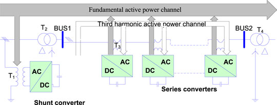
The general configuration of the DPFC device includes a shunt converter and multiple series converters, as shown in Figure 1. The shunt converter is similar to the shunt component of UPFC, injection power flow into the linked bus. Unlike the unified series component of UPFC with a larger rated capacity, the independent distributed lower capacity series converters of DPFC can provide similar effects based on the superposition theorem. Furthermore, there is a huge difference between the third harmonic characteristics of DPFC and the fundamental wave of UPFC on the principle of power flow control. The UPFC absorbs the fundamental frequency power flow on the shunt side and directly injects it into the series side through VSC1 and VSC2. However, the shunt converter of DPFC absorbs the fundamental frequency power flow and converts it into the third harmonic and then converts it back to the fundamental frequency power flow through the series converters, injected into the system.
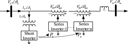
Based on the configuration and principle of DPFC, the independent capacity of a single series converter is small, and only after multiple series converters are added, power system requirements can be satisfied. A simplified DPFC circuit diagram can be derived, composed of a shunt inverter and multiple series inverters, as shown in Figure 2.
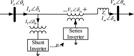
Figure 3 illustrates the cascade series inverters of DPFC superimposed into equivalent unified inverters based on the superposition theorem. The cascade DPFC on the series side can be modeled as an independent voltage source. The third harmonic power is nested in the operating condition, and only the base power flow is reflected in the static perspective. Referring to the equivalent voltage source model of UPFC, the following equation describes the equivalent process clearly for the DPFC series side:
As shown in Figure 3, the equivalent variables
For the KCL and KVL, the terminal voltage and current can be explained as follows:
The complex power of both DPFC series inverters and shunt inverts from Figure 3 is illustrated in Eqs 6–7:
where
There is a common similarity between UPFC and DPFC with its external feature of active power balance (Dai et al., 2019), and the active power flow from the shunt side to the series side holds conservation characteristics, as shown by
Combined with the complex power of the DPFC, in both the shunt and the series side with conservative characteristics, reactive power complies with the following equation, reflecting that the DPFC may generate or absorb reactive power after its injection into the power system.
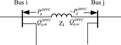
Due to the conservation characteristic of active power in the DPFC device, a power injection model (PIM) can be conducted as depicted in Figure 4:
where
3 Problem Formulation
A. The Relaxed AC-SOCP Model
The AC power flow model can be represented as
The above traditional model is non-linear. Therefore, the equivalent transformation is introduced to cope with the difficulties of the non-linear problem. Several variables are defined in the following equations:
The combined AC power flow model with Eqs 8, 9–11 is relaxed as follows:
According to Eqs 10–11, a constraint between
The above equation is still non-linear due to the quadratic form, and we relax the equality constraint to inequality format which can be transformed into an SOCP form:
Thus, the relaxed AC-SOCP model is transformed into an SOCP model with Eqs 12, 14, which can be solved by the commercial solvers such as CPLEX.
B. Two-Stage Stochastic MISOCP Model
The power system planners aim to determine the location allocations of DPFC, which can enhance the management efficiency of power flow and decrease the investment of DPFC. However, the operators desire to minimize the operation cost of injected DPFCs. Therefore, optimal location allocations of DPFC in the power system must consider the operational cost and investment of installing DPFCs. The optimal model is represented by
The objective function is to minimize the generation cost and investment cost of DPFC in Eq. 15. Equations 16, 17 hold the bus balance of active and reactive power. Equations 18–21 represent the upper bound and lower bound of active power, reactive power, voltage magnitude, voltage angle, and line power, respectively. The active power and reactive power of line with relaxed SOCP power flow are reformulated in Eq. 22, and we set the line apparent power constraints with the DPFC in Eqs 23, 24. Equations 25, 26 constrain the installation capacity and number of DPFCs.
The formulated MISOCP problem aims to optimize the location and ratings of DPFC under the base level. Once the DPFC is injected into the grid, the device should offer functions under different load–wind conditions with its fixed locations, and the above MISOCP model must cover different scenarios. We develop a two-stage stochastic approach to determine the optimal locations and ratings with a hybrid model of DPFC to accelerate its efficiency.
4 Solution Approach
A. DC Power Flow With Reactance Model of DPFC
Based on the conservation of active power and unbalance of reactive power in the DPFC, a reactance model of DPFC can be shown in Figure 5.
The equivalent reactance
where
According to Eq. 6, the DPFC can absorb or generate reactive power, and the equivalent compensation level of the series reactance of the DPFC bounds the value between −0.2 and 0.7. Consequently, the corresponding linear interval is between −0.17 and 2.33.
The DC power flow approximation is widely used in power planning, which supposes voltage magnitude equal to 1 p.u. and ignores reactive power and resistance of lines because of
Once the DPFC is injected to the system, the reactance of two adjacent buses is changed from
The active power of the transmission line can be varied with DPFC injection with the updated reactance
There is a non-linear variable term
The active power in Eq. 31 can be rewritten as
Combining Eqs 32, 33, we multiply both sides of the equation with a voltage angle difference of
The feasible range of variables
In the optimization process, one of Eqs 36, 37 is valid, and another one is always useful because of the large number
Note that the bilinear term
Combining Eqs 36–37 with the dummy variable
Hence, the DC power flow with the DPFC, including Eqs 31, 39–41, is reformulated into an MILP problem.
B. Two-Stage Stochastic Optimal Location Allocations of DPFC
Due to the unrepeated features of DPFC planning, we develop a two-stage optimization method based on Benders decomposition to solve the MISOCP problem under different wind–load scenarios. The original MISOCP problem can be decomposed into an MILP master problem and an SOCP subproblem. The MILP problem is to solve the optimal locations of DPFC under the baseload case, and the relaxed DC power flow based on the reactance model of DPFC accelerates its efficiency. In contrast, the optimal ratings of DPFC with various scenarios are obtained in the SOCP subproblem.
The master problem is represented as
Equation 42 is the objective function of master problem, which is explicitly reflected in the lower bound. In the objective function, the first term is the generation cost, while the latter is the investment cost of DPFC. The relax DC active power balance is constrained in the second column of Eq. 42, whose non-linearized term is linearized using the big-M method. The second column in Eq. 42 is the Benders cuts generated in the subproblem to accelerate the solution efficiency.
The active power balance of the SOCP subproblem may be challenging because of wind–load uncertainty. Slack variables are incorporated into the power balance equations to relax and ensure the feasibility of the subproblem. The stochastic SOCP subproblem is represented by Eq. 44.
The subproblem is as follows:
Equation 44 represents the subproblem objective function, which consists of the investment cost of DPFC and the sum of relaxing slack variables. The constraints are updated under various scenarios, and some slack variables are introduced into the power flow constraints to ensure the convergence of power flow. Hence, the constraints of active and reactive power are also rewritten with the slack variables. The dual of Benders cuts is obtained from the latter columns of Eq. 44. However, the duals of cuts need to be reconstructed because of load/wind uncertainty. We reformulate the expected value of duals associated with numerous scenarios, as shown in the following equations:
Based on the Benders decomposition method, the two-stage problem has a lower bound and upper bound. The Benders cuts accelerate the optimization efficiency iteratively and move the solution toward optimality. A stop criterion is justified as the optimal solution to the original problem. The upper bound of MISOCP and stop criterion is established, as shown in the following equations:
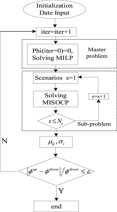
The flowchart of two-stage stochastic optimization is depicted in Figure 6.
For a given gap
Step 1: Let
Step 2: Solve the MP which is modeled in Eq. 42,
Obtain the output of generators
Update the lower bound
Step 3: Fix the location of DPFC and output of thermal units and solve the SP considering various wind–load scenarios,
Obtain compensation levels
Update the upper bound
Step 4: If
5 Case Study
A. Verification of the Relaxed AC-SOCP Model
In this section, several power flow cases are utilized to illustrate the effectiveness of the proposed model. The numerical cases are tested on the IEEE 118 bus system. The data of IEEE 118 are obtained from MATPOWER 6.0.
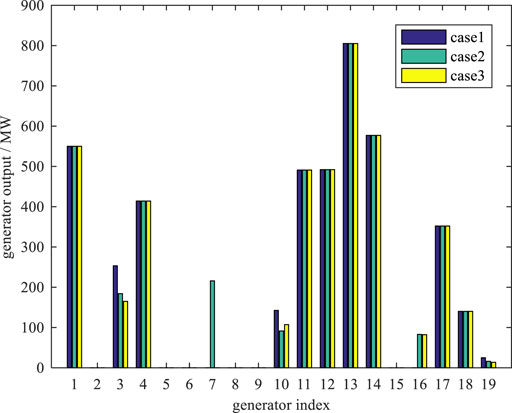
Case 1: the proposed relaxed DC power flow in Section 3.1A, which is solved by GAMS/CPLEX.
Case 2: the traditional non-linear power flow in Eq. 8, which is solved by GAMS/CONOPT.
Case 3: the proposed SOCP model in Eq. 22, which is solved by GAMS/CPLEX.
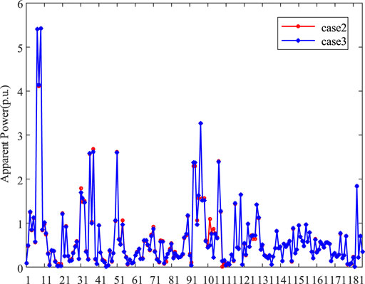
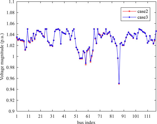
As for the power flow analysis, we only consider the original power flow without DPFC. Compared to Case 2 and Case 3, Case 1 cannot simulate the AC power characteristic. Figure 7 depicts apparent power of lines in Case 2 and Case 3, and the difference of the two solutions is less than 1%. Figure 8 also compares the bus voltage performance between Case 2 and Case 3, and the voltage magnitude of the two cases is fairly close. Figure 9 shows significant differences of generation output in the three cases. The generation dispatch solution of Case 1 shows a different trend because of ignoring reactive power constraints, whereas the dispatch solutions show highly consistent characteristics between Case 2 and Case 3.
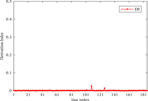
To illustrate the accuracy of the relaxed AC-SOCP model, we define a deviation index stated in (), which depicts the gap of line constraints between the non-linear AC power flow and the relaxed AC-SOCP model. Figure 10 shows the gap performance, which is almost zero for all lines:
B. Effect of the Optimal DPFC With High Penetration of Wind Power
To verify the proposed method, we conducted case studies on the modified IEEE 118 bus system. The baseload is 4242 MW, and the capacity of the total generator is 5,859.2 MW. The load uncertainty is statistically based on the Latin hypercube sampling (LHS) (Le and Wu, 2021) and K-means clustering method (Toyoda and Wu, 2021; Wu, 2021), as shown in Table 1. There is an artificially decreased capacity to create congestion with the thermal limits of transmission lines. GAMS implements the procedure, the MILP master problem is solved by GAMS/CPLEX, and GAMS/CPLEXD solves the SOCP subproblem. The threshold values of the stop criterion are set to be 1e-4.
A. The Performance With Different Numbers and Ratings of DPFCs
There are three huge impacts with different numbers of optimal DPFCs’ planning. Table 2 shows the total operation cost with different numbers of optimal location allocation. The operating cost of power systems shows a downward trend as the numbers of installed DPFCs increase because of their power flow management of DPFC. Compared to the optimal locations, there is a continuous trend, which verifies the robustness of the optimal planning program and overcomes the drawbacks of the iterative planning method. The level of wind absorption has also been improved. However, the increment level is not obvious between the two-DPFC and three-DPFC planning, which closely achieves the extreme in the system (Table 3):
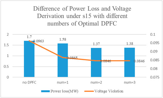
With different installing numbers of DPFCs, the voltage violation and power loss of the system are shown in Figure 11. The system voltage fluctuations gradually decrease as the number of DPFCs increases, whereas the increment of power loss has a positive trend.
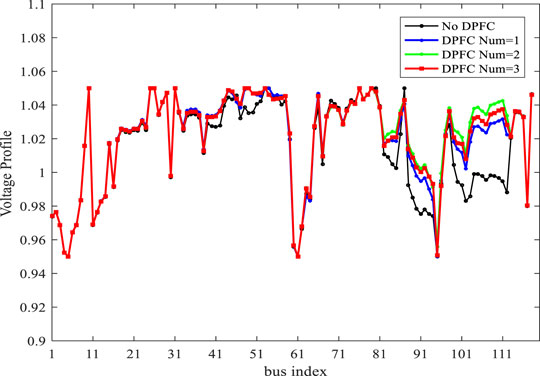
Figure 12 shows a great advantage of voltage stability with three DPFCs installed over the others.
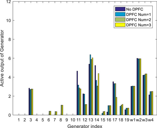
To evaluate the effects of DPFC on generator rescheduling, the output of generators under a loading operation with scenario s15 is shown in Figure 13. The generator dispatch has a considerable difference from the DPFC under the load level. Comparing the no-DPFC and one-DPFC solutions, the absorption of wind power in this scenario has little change. However, the output of thermal unit is significantly different because more economical units participate in more dispatch plans, which verifies the management efficiency of DPFC to the dispatch solution of thermal generators. Once two or three DPFCs are injected into the system, the wind absorption has an obvious increment, which illustrates the power flow shiftable capability of DPFC.
The Performance With Certain Compensation Level of DPFC
When the compensation level of DPFC is equal to 5 MW, the performance is different from that in Table 2. It is observed that the expected cost decreases slightly as the number of DPFCs increases. The wind penetration also shows little changes. This result also confirms the superiority of the planning method, in which the location and allocation are optimized simultaneously.
C. The Performance With Variable Wind Location With Optimal DPFC
To assess the impact of optimal DPFC solutions with varied wind locations, we transfer the wind location to bus [3,50,80,118]. Comparing Tables 2, 4, the overall decline in wind power penetration is relatively obvious, which only can illustrate the manage ability of DPFC is subjected to the structure of generators. At the same time, it can be observed that the operating cost and wind penetration also show a positive trend when DPFC numbers increased.
6 Conclusion
This work presents a novel two-stage stochastic optimization model, which simultaneously optimizes the location and compensation level of DPFCs considering various wind–load scenarios. Case studies are performed to demonstrate the effectiveness of the proposed method. The conclusions are summarized as follows:
1) The relaxed AC-SOCP model can easily simulate the non-linear AC power flow and has an advantage of solving speed and difficulties.
2) The proposed two-stage method has a consistent scheduling plan of DPFC, which maintains the non-linear internal characteristics of DPFC and overcomes the drawback of iterative scheduling planning.
3) The power flow management of DPFC on the network side plays an important role in system operation. The operating cost, power flow performance, and wind absorption have a positive trend as the numbers of DPFCs increased.
In addition, the methodology proposed in this paper is applicable to the areas of strengthening the management efficacy on the network side. Also in the future work, we will test the DPFC in more scenarios to check its control capability.
Data Availability Statement
The original contributions presented in the study are included in the article/Supplementary Material, and further inquiries can be directed to the corresponding author.
Author Contributions
XZ wrote the manuscript and performed the method. LD provided the financial support for this research. JW provided the support for solving method.
Funding
This research was supported by the State Grid Corporation of China (No. 52150016000Y).
Conflict of Interest
The authors declare that the research was conducted in the absence of any commercial or financial relationships that could be construed as a potential conflict of interest.
Publisher’s Note
All claims expressed in this article are solely those of the authors and do not necessarily represent those of their affiliated organizations, or those of the publisher, the editors, and the reviewers. Any product that may be evaluated in this article, or claim that may be made by its manufacturer, is not guaranteed or endorsed by the publisher.
References
Alomoush, M. I. (2003). Derivation of UPFC DC Load Flow Model with Examples of its Use in Restructured Power Systems. IEEE Trans. Power Syst. 18 (3), 1173–1180. doi:10.1109/tpwrs.2002.805002
Alomoush, M. I. (2004). Impacts of UPFC on Line Flows and Transmission Usage. Electric Power Syst. Res. 71 (3), 223–234. doi:10.1016/j.epsr.2004.01.017
Bhowmick, S., Das, B., and Kumar, N. (2008). An Indirect UPFC Model to Enhance Reusability of Newton Power-Flow Codes. IEEE Trans. Power Deliv. 23 (4), 2079–2088. doi:10.1109/tpwrd.2008.923105
Dai, J., Tang, Y., Liu, Y., Ning, J., Wang, Q., Zhu, N., et al. (2019). Optimal Configuration of Distributed Power Flow Controller to Enhance System Loadability via Mixed Integer Linear Programming. J. Mod. Power Syst. Clean. Energ. 7 (6), 1484–1494. doi:10.1007/s40565-019-0568-8
Dawn, S., and Tiwari, P. K. (2016). Improvement of Economic Profit by Optimal Allocation of TCSC & UPFC with Wind Power Generators in Double Auction Competitive Power Market. Int. J. Electr. Power Energ. Syst. 80, 190–201. doi:10.1016/j.ijepes.2016.01.041
Ding, T., Bo, R., and Li, F. (2015). Optimal Power Flow with the Consideration of Flexible Transmission Line Impedance[J]. IEEE Trans. Power Syst. 31 (2), 1655–1656. doi:10.1109/tpwrs.2015.2412682
Ebeed, M., Kamel, S., Yu, J., and Jurado, F. (2019). Development of UPFC Operating Constraints Enforcement Approach for Power Flow Control. IET Generation, Transm. Distribution 13 (20), 4579–4591. doi:10.1049/iet-gtd.2018.5609
Hemmati, R., Hooshmand, R. A., and Khodabakhshian, A. (2013). Comprehensive Review of Generation and Transmission Expansion Planning. IET Generation, Transm. Distribution 7 (9), 955–964. doi:10.1049/iet-gtd.2013.0031
Hooshmand, R.-A., Morshed, M. J., and Parastegari, M. (2015). Congestion Management by Determining Optimal Location of Series FACTS Devices Using Hybrid Bacterial Foraging and Nelder-Mead Algorithm. Appl. Soft Comput. 28, 57–68. doi:10.1016/j.asoc.2014.11.032
Jabr, R. A. (2013). Optimization of AC Transmission System Planning. IEEE Trans. Power Syst. 28 (3), 2779–2787. doi:10.1109/tpwrs.2012.2228507
Khanchi, S., and Garg, V. K. (2013). Unified Power Flow Controller (FACTS Device): A Review[J]. system 5, 6.
Le, Shuting., and Wu, Yuhu. (2021). Game Theoretic Approach for a Service Function Chain Routing in NFV with Coupled Constraints. IEEE Trans. Circuits Syst..68:3557 doi:10.1109/TCSII.2021.3070025
Li, Z., Jiang, W., Abu-Siada, A., Li, Z., Xu, Y., and Liu, S. (2021). Research on a Composite Voltage and Current Measurement Device for HVDC Networks. IEEE Trans. Ind. Electron. 68 (9), 8930–8941. doi:10.1109/tie.2020.3013772
Nikoobakht, A., Aghaei, J., Parvania, M., and Sahraei‐Ardakani, M. (2018). Contribution of FACTS Devices in Power Systems Security Using MILP‐based OPF. IET Generation, Transm. Distribution 12 (15), 3744–3755. doi:10.1049/iet-gtd.2018.0376
Noroozian, M., Angquist, L., Ghandhari, M., and Andersson, G. (1997). Use of UPFC for Optimal Power Flow Control. IEEE Trans. Power Deliv. 12 (4), 1629–1634. doi:10.1109/61.634183
Orfanogianni, T., and Bacher, R. (2003). Steady-state Optimization in Power Systems with Series Facts Devices. IEEE Trans. Power Syst. 18 (1), 19–26. doi:10.1109/tpwrs.2002.807110
Pereira, M., and Zanetta, L. C. (2012). A Current Based Model for Load Flow Studies with UPFC[J]. IEEE Trans. Power Syst. 28 (2), 677–682.doi:10.1109/tpwrs.2012.2206409
Prasad, J. V., Ram, I. S., and Jayababu, B. (2011). Genetically Optimized FACTS Controllers for Available Transfer Capability Enhancement[J]. Int. J. Comp. Appl. 975, 8887.doi:10.5120/2349-3072
Rajabi-Ghahnavieh, A., Fotuhi-Firuzabad, M., and Othman, M. (2015). Optimal Unified Power Flow Controller Application to Enhance Total Transfer Capability[J]. IET Generation. Transm. Distribution 9 (4), 358–368.doi:10.1049/iet-gtd.2014.0110
Ranganathan, S., Surya Kalavathi, M., and Asir Rajan C., C. (2016). Self‐adaptive Firefly Algorithm Based Multi‐objectives for Multi‐type FACTS Placement. IET Generation, Transm. Distribution 10 (11), 2576–2584. doi:10.1049/iet-gtd.2015.0905
Sahraei-Ardakani, M., and Hedman, K. W. (2015). A Fast LP Approach for Enhanced Utilization of Variable Impedance Based FACTS Devices[J]. IEEE Trans. Power Syst. 31 (3), 2204–2213.doi:10.1109/pesgm.2016.7741200
Sang, Y., and Sahraei-Ardakani, M. (2017). The Interdependence between Transmission Switching and Variable Impedance Series FACTS Devices[J]. IEEE Trans. Power Syst. 33 (3), 2792–2803. doi:10.1109/tpwrs.2017.2756074
Saravanan, M., Slochanal, S. M. R., and Venkatesh, P. (2007). Application of Particle Swarm Optimization Technique for Optimal Location of FACTS Devices Considering Cost of Installation and System Loadability[J]. Electric Power Syst. Res. 77 (3-4), 276–283. doi:10.1016/j.epsr.2006.03.006
Sarker, J., and Goswami, S. K. (2014). Solution of Multiple UPFC Placement Problems Using Gravitational Search Algorithm. Int. J. Electr. Power Energ. Syst. 55, 531–541. doi:10.1016/j.ijepes.2013.10.008
Shen, Xun., Ouyang, Tinghui., Li, Yuanchao., and Khajorntraidet, Chanyut. (2021). “Mixture Density Networks-Based Knock Simulator”. IEEE/ASME Trans. Mechatronics, Early Access. doi:10.1109/TMECH.2021.3059775
Shen, Xun., Ouyang, Tinghui., Yang, Nan., and Zhuang, Jiancang. (2021). “Sample-based Neural Approximation Approach for Probabilistic Constrained Programs”. IEEE Trans. Neural Networks Learn. Syst. Early Access. doi:10.1109/TNNLS.2021.3102323
Shen, Xun., and Raksincharoensak, Pongsathorn. (2021). “Pedestrian-aware Statistical Risk Assessment”. IEEE Trans. Intell. Transportation Syst. Early Access, 1. doi:10.1109/TITS.2021.3074522
Shen, Xun., and Raksincharoensak, Pongsathorn. (2021). “Statistical Models of Near-Accident Event and Pedestrian Behavior at Non-signalized Intersections. J. Appl. Stat. Early Access. 1.doi:10.1080/02664763.2021.1962263
Singh, S. P. (2016). Congestion Mitigation Using UPFC[J]. IET Generation. Transm. Distribution 10 (10), 2433–2442.doi:10.1049/iet-gtd.2015.1199
Tang, A., Lu, Z., and Yang, H. (2020). Digital/analog Simulation Platform for Distributed Power Flow Controller Based on ADPSS and dSPACE[J]. CSEE J. Power Energ. Syst. 7 (1), 181–189.
Tang, A., Shao, Y., Huang, Y., and Xu, Q. (2018). A New Topology of the Distributed Power Flow Controller and its Electromagnetic Transient Characteristics. Electric Power Syst. Res. 163, 280–287. doi:10.1016/j.epsr.2018.07.002
Tiwari, P. K., and Sood, Y. R. (2013). An Efficient Approach for Optimal Allocation and Parameters Determination of TCSC with Investment Cost Recovery under Competitive Power Market. IEEE Trans. Power Syst. 28 (3), 2475–2484. doi:10.1109/tpwrs.2013.2243848
Tiwari, P. K., and Sood, Y. R. (2012). Efficient and Optimal Approach for Location and Parameter Setting of Multiple Unified Power Flow Controllers for a Deregulated Power Sector. IET Gener. Transm. Distrib. 6 (10), 958–967. doi:10.1049/iet-gtd.2011.0722
Toyoda, M., and Wu, Y. (2021). Mayer-type Optimal Control of Probabilistic Boolean Control Network with Uncertain Selection Probabilities. IEEE Trans. Cybern. 51, 3079–3092. doi:10.1109/tcyb.2019.2954849
Tripathy, M., and Mishra, S. (2007). Bacteria Foraging-Based Solution to Optimize Both Real Power Loss and Voltage Stability Limit. IEEE Trans. Power Syst. 22 (1), 240–248. doi:10.1109/tpwrs.2006.887968
Tripathy, M., Mishra, S., Lai, L. L., and Zhang, Q. P. (2006). Transmission Loss Reduction Based on FACTS and Bacteria Foraging algorithm[M]//Parallel Problem Solving from Nature-PPSN IX. Springer, Berlin, Heidelberg.
Ugranli, F., Karatepe, E., and Nielsen, A. H. (2016). MILP Approach for Bilevel Transmission and Reactive Power Planning Considering Wind Curtailment[J]. IEEE Trans. Power Syst. 32 (1), 652–661.
Verma, K. S., and Gupta, H. O. (2006). Impact on Real and Reactive Power Pricing in Open Power Market Using Unified Power Flow Controller. IEEE Trans. Power Syst. 21 (1), 365–371. doi:10.1109/tpwrs.2005.857829
Vo Tien, D., Goňo, R., and Leonowicz, Z. (2019). Load Flow Analysis in Power System Network Incorporating Statcom: A Comparison of the Direct and Indirect Algorithm of the newton-raphson method[J].
Wu, Y. (2021). Yuqian Guo, Mitsuru Toyoda, Policy Iteration Approach to the Infinite Horizon Average Optimal Control of Probabilistic Boolean Networks. IEEE Trans. Neural Networks Learn. SystemsVol 32 (6), 2910–2924. doi:10.1109/tnnls.2020.3008960
Yang, N. (2021). A Comprehensive Review of Security-Constrained Unit Commitment. J. Mod. Power Syst. Clean Energ.. doi:10.35833/MPCE.2021.000255
Yang, N., Qin, T., Wu, L., Huang, Y., Huang, Y., and Xing, C. (2021). A Multi-Agent Game Based Joint Planning Approach for Electricity-Gas Integrated Energy Systems Considering Wind Power Uncertainty. Electric Power Syst. Res., 107673. doi:10.1016/j.epsr.2021.107673
Yang, N., Yang, C., Wu, L., Shen, X., Jia, J., Li, Z., et al. (2021). Intelligent Data-Driven Decision-making Method for Dynamic Multi-Sequence: An E-Seq2Seq Based SCUC Expert System. IEEE Trans. Ind. Inform. doi:10.1109/TII.2021.3107406
Yang, N., Yang, C., Xing, C., Ye, D., Jia, J., Chen, D., et al. (2021). Deep Learning-Based SCUC Decision-Making: An Intelligent Data-Driven Approach With Self-Learning Capabilities. IET Gener. Transm. Distrib., 1–12. doi:10.1049/gtd2.12315
Yuan, Z., de Haan, S. W. H., Ferreira, J. B., and Cvoric, D. (2010). A FACTS Device: Distributed Power-Flow Controller (DPFC). IEEE Trans. Power Electron. 25 (10), 2564–2572. doi:10.1109/tpel.2010.2050494
Zhang, L., Xie, Y., Ye, J., Xue, T., Cheng, J., Li, Z., et al. (2021). Intelligent Frequency Control Strategy Based on Reinforcement Learning of Multi-Objective Collaborative Reward Function. Front. Energ. Res. 9. 760525.doi:10.3389/fenrg.2021.760525
Zhang, T., Xu, X., and Li, Z. (2020). Optimum Location and Parameter Setting of STATCOM Based on Improved Differential Evolution Harmony Search Algorithm[J]. IEEE Access.8:87810. doi:10.1109/access.2020.2993066
Glossary
Sets and indices
Keywords: distributed power flow controller, relaxed AC-SOCP, Benders decomposition, uncertainty, optimal FACTS
Citation: Zhu X, Dichen L and Wu J (2022) Two-Stage Optimal Location Allocations of DPFC Considering Wind and Load Uncertainty. Front. Energy Res. 10:865902. doi: 10.3389/fenrg.2022.865902
Received: 30 January 2022; Accepted: 11 February 2022;
Published: 18 March 2022.
Edited by:
Xun Shen, Tokyo Institute of Technology, JapanReviewed by:
Hardeep Singh, Sophia University, JapanSahil Sardana, Indian Institute of Technology Dhanbad, India
Copyright © 2022 Zhu, Dichen and Wu. This is an open-access article distributed under the terms of the Creative Commons Attribution License (CC BY). The use, distribution or reproduction in other forums is permitted, provided the original author(s) and the copyright owner(s) are credited and that the original publication in this journal is cited, in accordance with accepted academic practice. No use, distribution or reproduction is permitted which does not comply with these terms.
*Correspondence: Jun Wu, Ynlyb253dUB3aHUuZWR1LmNu
 Xuedong Zhu
 Liu Dichen