 Chao Xing
 Junhao Chen1,2
- 1Electric Power Research Institute of Yunnan Power Grid Co., Ltd., Kunming, China
- 2School of Electric Power Engineering, Kunming University of Science and Technology, Kunming, China
Due to the poor performance of traditional STATCOM in DC engineering, a compensation method using battery energy storage STATCOM (STATCOM/BESS) to suppress commutation failure of the weak receiving-end high voltage direct current transmission system is proposed, and its effect is better than traditional STATCOM. First, the mechanism and influencing factors of commutation failure are analyzed; the extinction angle of the converter valve is taken as the decision index of commutation failure; the relationship between various electrical parameters and extinction angle is studied under the condition of the single-phase grounding fault on the inverter side. Second, according to the differences between the positive and negative sequence reactive current output by STATCOM/BESS when a fault occurs in single-phase grounding, a compensation method is proposed to suppress commutation failure by STATCOM/BESS, which increases the proportion of positive sequence reactive current output by STATCOM/BESS under the condition of constant output so as to reduce the probability of commutation failure. At last, STATCOM/BESS is added into the standard model of LCC-HVDC for the simulation experiment and compared with conventional running characteristics of STATCOM in order to verify the effect of STATCOM/BESS in suppressing commutation failure.
Introduction
High voltage direct current (HVDC) transmission technology can not only meet the demand of large capacity and long distance transmission of electric energy but also reduce the loss of electric energy in transmission lines; (Shen et al., 2021) thus, it becomes an important means of electric energy transmission between long distance and large area power grids (Peng et al., 2017). When the power at the receiving end of the HVDC transmission system is weak, the AC system at the inverter side breaks down, which easily leads to the commutation failure of the HVDC system, resulting in the increase of DC current amplitude, the decrease of DC voltage amplitude, and voltage waveform distortion, etc., which seriously threatens the safety and reliability of the power grid (Huang, 2006). The fundamental condition of inverter commutation failure is that the extinction angle γ of a certain commutation valve is less than its intrinsic limit extinction angle γmin (Zhao et al., 2015). The factors causing converter commutation failure include internal factors and external factors of the inverter system, (Zhenhua et al., 2021) among which one of the most common factors of commutation failure is caused by commutation voltage drop raised by AC grid fault.
At present, in order to support the grid voltage and restrain the commutation failure of the HVDC system, reactive compensation equipment has been put into many weak receiving-end system inverter stations, among which the dynamic response of STATCOM is pretty fast during operation, and the effect of restraining commutation failure is remarkable. Guo et al. (2013) has modeled the whole connection of STATCOM into the doubly-fed HVDC system and pointed out that STATCOM can effectively support the receiving-end bus of the doubly-fed system within a reasonable electrical distance so as to improve the system performance and avoid commutation failure within a certain range. In Zhang (2011), the apparent short-circuit ratio increment (ASCRI) is defined to reflect the change of the strength of the receiving-end system after adding STATCOM. The theoretical and simulation results show that the ASCRI index of the system after adding STATCOM is greater than 0, and the ASCRI is positively correlated with the capacity of the added STATCOM within a certain range, which indicates that STATCOM can support the voltage of the receiving-end AC power grid, and can avoid the commutation failure of the HVDC system to a certain extent. However, when traditional STATCOM performs large-capacity reactive power compensation, it will affect the control accuracy of DC side voltage and lead to large fluctuations of DC side voltage. The energy storage STATCOM combining energy storage technology with reactive power compensation technology makes up for the shortcomings of traditional STATCOM in HVDC system application. In Virtanen et al. (2013), energy storage STATCOM is used to increase the voltage of the parallel connection point with an electric arc furnace load, and the voltage drop of the parallel connection point was reduced from 15% to 2%. In Liang (2014), the whole switch function model of STATCOM/BESS is established, and the power feedforward control is introduced, and a prototype of STATCOM/BESS with a capacity of 10kVA is built. The simulation and experiment show that the proposed topology and control method can enhance the stability of the system and restrain the power fluctuation of the wind farm.
Compared with traditional STATCOM, (Guobing et al., 2020) STATCOM/BESS has more advantages in improving the stability of the power system. The traditional way to maintain the stability of the power system is to strengthen the network structure, improve the performance of the prime mover and the excitation system, cut off the machine, cut the load, and use the STATCOM device to provide dynamic reactive power to support the system voltage, but it cannot perform active power regulation to dampen. Apart from the power oscillation of the system, these methods inevitably have their own limitations. As a new type of FACTS device, STATCOM/BESS is composed of a high-power power electronic converter and an energy storage system. He et al. (2020) A large-capacity energy storage device is added to the DC side of the converter and is connected to the power grid in parallel. It absorbs and releases active and reactive power quickly and has the ability of four-quadrant operation. At present, there is less application research in the field of DC transmission, especially in the suppression of commutation failure. Therefore, this article studies the commutation failure suppression of the HVDC system and puts forward the compensation method to suppress commutation failure by STATCOM/BESS under single-phase grounding fault. The STATCOM/BESS is added in the HVDC system during the experiment, which shows that the effect of STATCOM/BESS on suppression of commutation failure is better than that of traditional STATCOM.
HVDC Commutation Failure and Its Influencing Factors
HVDC Commutation Failure
Thyristor converter valves are used in the HVDC transmission system. During the process of commutation, if the process is not completed or the blocking ability is not restored within a period of time under the action of reverse voltage, the commutated valves will switch phases to the valves scheduled to be turned off when the voltage on the valve side becomes positive. This phenomenon is called commutation failure. Lei et al. (2021) From the thyristor device level, it takes a certain time for the thyristor to complete the carrier recombination and restore the blocking ability. γmin represents the recovery time of the thyristor valve, expressed by the electrical angle, which is about 10. It reflects the shortest time for the thyristor to bear the reverse voltage when restoring the blocking ability. When the extinction angle γ < γmin is calculated, the commutation is considered to be failed.
Figure 1 is the topology of the inverter, in which T1∼T6 are thyristors, and Xa ∼ Xc are commutation reactive resistances of each phase. Id represents direct current; and va, vb, and vc are the three-phase voltages of the AC system bus. Eq. 1 represents the extinction angle-related commutation (Cai et al., 2019):
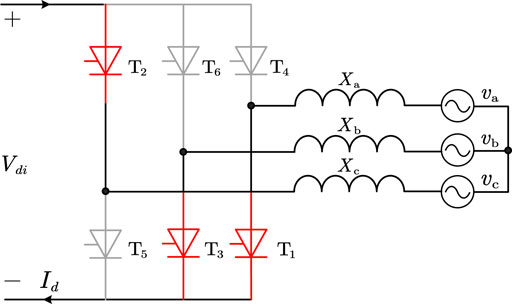
FIGURE 1. Inverter Grez bridge structure.
If the fault causes commutation voltage asymmetry, the offset of this voltage crossing the zero point should be considered in the aforementioned formula, then the offset of commutation voltage crossing the zero point should be written as φ, and the expression of γ at this time can be shown (Li et al., 2017) as:
In Eqs 1, 2, k represents the commutation ratio, Id represents the direct current, Xc represents the commutation reactive resistance, E represents the effective value of the commutation bus line voltage, and β represents the leading trigger angle.
The Influencing Factors of Commutation Failure
It can be seen from Eq. 2 that the occurrence of commutation failure depends on many factors, including electrical factors such as AC bus voltage, DC current, commutation reactive resistance, and commutation voltage offset angle, and control factors such as trigger angle. The following mainly analyzes the influence of AC bus voltage and DC current on commutation failure when the AC system at the receiving end fails.
The Influence of Bus Voltage Amplitude Drop on Commutation Failure
When a short-circuit fault occurs in an AC system, it is assumed that the leading trigger angle β and the change ratio k are unchanged in a short time. Mitsuru and Yuhu (2021) In order to analyze the influence of the AC bus voltage Ull on the commutation failure on the inverter side, the sensitivity of its extinction angle γ can be used. The deviation of γ on the bus voltage Ull can be obtained by using Eq. 2:
When other parameters are unchanged, the relationship between bus voltage and sensitivity of the extinction angle is shown in Figure 2. The smaller the converter bus voltage is, the greater its sensitivity to extinction angle is, that is, the smaller the converter bus voltage is, the faster the extinction angle decreases, and the more likely it is to have commutation failure.
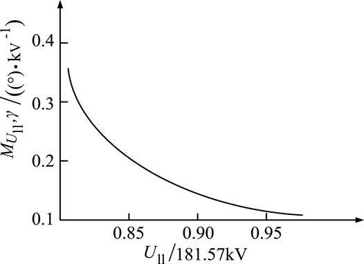
FIGURE 2. Sensitivity of Ull to γ.
The Influence of DC Current Surge on Commutation Failure
The AC voltage drop usually causes the DC current to rise, and the DC current rise will have a certain limit. When the AC voltage on the valve side drops to a certain value, the system will start the link of “low voltage and current limit,” thus controlling the continuous rise of DC current, and ensuring the stable operation of the DC transmission system (Zhu, 2008). In order to analyze the influence of DC current Id on the extinction angle, the deviation of extinction angle γ on DC current Id is calculated according to Eq. 2:
Under other conditions unchanged, the relationship between DC current and sensitivity of the extinction angle is shown in Figure 3. Yang (2021) The sensitivity of DC current Id to extinction angle γ is negative, and the greater the Id is, the greater its sensitivity to γ will be, so the increase of Id will also lead to the decrease of extinction angle γ, and the greater the Id is, the faster the γ will decrease, which will easily lead to commutation failure.
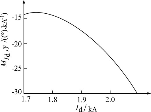
FIGURE 3. Sensitivity of Id to γ.
Analysis of the Single-Phase Grounding Fault in the AC System on the Inverter Side
A single-phase grounding fault is the most common asymmetric fault in the power system, characterized by the voltage drop, and phase shift of one phase on the bus line after the fault, which will affect the other two phases in the weak receiving end of the AC system, and the influence on the extinction angle is relatively complex. Take the single-phase grounding short-circuit fault in phase A of the AC power grid as an example, and the fault phase voltage is shown in Figure 4 (Mohan, 2021).
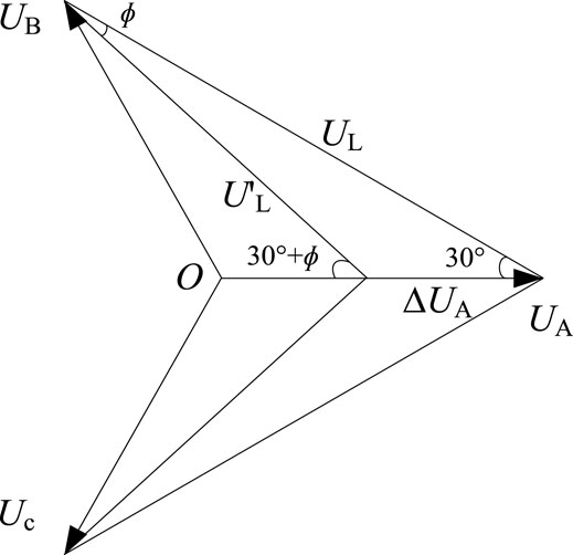
FIGURE 4. Fault voltage phasor diagram.
It can be seen from Figure 4 that when the grounding short-circuit fault occurs in phase A and the amplitude of phase voltage decreases by ΔUA, the amplitude of line voltages UAB and UCA will decrease then the zero point of line voltage will shift. According to the trigonometric function theorem (all expressed in standard values) (Muniappan, 2021):
Therefore, when an asymmetric fault occurs on the AC side of the system, the calculation formula of the extinction angle γ becomes:
In the formula, UL′ represents the voltage value of the commutation line after the fault, and φ represents the angle value of zero crossing point of commutation line voltage caused by the asymmetric fault. Shen and Raksincharoensak (2021) It can be seen that when an asymmetric fault occurs in the AC system on the inverter side, the change of commutation voltage affects the extinction angle, and the phase shift caused by the zero crossing of commutation line voltage also changes the extinction angle. In addition, (Yu et al., 2020) the influence of the single-phase fault on different line voltages is different. Taking the A-phase short-circuit fault as an example, the influence of the single-phase fault on the valve commutation process among A-phase, B-phase, and C-phase bridge arms will be discussed as follows:.
1) Valve 1 commutates to valve 3, and valve 4 commutates to valve 6, that is, the valve on the A-phase bridge arm commutates to the valve on the B-phase bridge arm. When A-phase is grounded in a single phase, the extinction angle γ is:
It can be seen from Eq. 8 that under the condition of certain system parameters, the change of the evalve extinction angle is related to the degree of voltage drop of A-phase. According to CIGRE standard system parameters (Table 1 below), the function graph of the extinction angle can be drawn in MATLAB as shown in Figure 5.
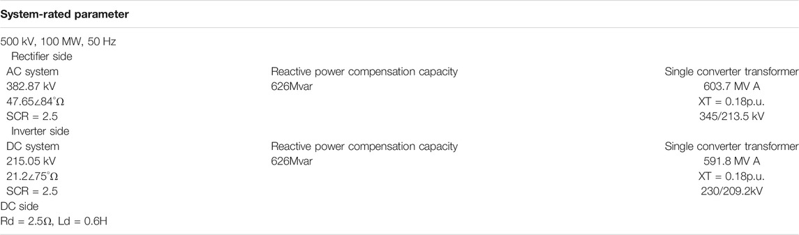
TABLE 1. CIGRE standard system parameters.

FIGURE 5. Function diagram of the extinction angle of valves 1 and 4.
It can be seen from the aforementioned figure that when A-phase is grounded in a single phase, (Yuhu et al., 2021) the extinction angles of valves 1 and 4 decrease monotonously with the increase of ΔUA. When ΔUAmax = 0.10pu, γ < γmin, it is judged that commutation failure occurs, while when ΔUA < ΔUAmax, it is considered that commutation failure will not occur.
2) Valve 2 commutates to valve 4, and valve 5 commutates to valve 1, that is, the valve on the C-phase bridge arm commutates to the valve on the A-phase bridge arm. When the A-phase is grounded in a single phase, the function image of the extinction angle γ is also obtained in MATLAB as shown in Figure 6.
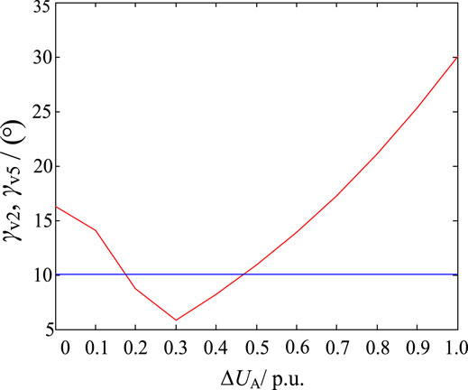
FIGURE 6. Function diagram of the extinction angle of valves 2 and 5.
It can be seen from the variation curve in Figure 6 that the extinction angle of valves 2 and 5 is not monotonic with ΔUA. It can be obtained from the intersection point with the straight line γmin = 10° that when A-phase is grounded in a single phase, the interval of commutation failure of valves 2 and 5 is 0.18pu < ΔUA < 0.46pu. In other intervals, it is considered that commutation failure will not occur.
3) Valve 3 commutates to valve 5, and valve 6 commutates to valve 2, that is, the valve on the B-phase bridge arm commutates to the valve on the C-phase bridge arm. It can be seen from Figure 5 that the single-phase grounding of A-phase has no effect on the line voltage between B-phase and C-phase, so it has no effect on the extinction angles of valves 3 and 6. Theoretically, it is considered that the γ values of the two valves are unchanged in this type of the single-phase grounding fault.
Similarly, the influence of single-phase grounding of phases B and C on the commutation process can be analyzed.
Compensation Method of STATCOM/BESS Suppression Commutation Failure Under the Single-phase Grounding Fault
According to the analysis of the single-phase grounding fault in the previous section, the short-circuit fault of A-phase has the least influence on the commutation voltage between B-phase and C-phase, (Yang et al., 2021b) while it has the greatest negative influence on the commutation voltage between A-phase and B-phase, and the probability of commutation failure is also the largest. Therefore, under the single-phase fault condition, the ratio and capacity of positive and negative sequence components of STATCOM/BESS reactive current are controlled to reduce the probability of commutation failure.
The Influence of STATCOM/BESS Positive and Negative Sequence Reactive Power Compensation Components on the Extinction Angle
Figure 7 shows the schematic diagram of the LCC-HVDC receiving-end system including STATCOM/BESS. Le et al. (2021) In the figure, Idc represents DC current of the inverter station, Ihvdc represents output current of the inverter station, Ut represents phase voltage of the converter bus, Ist represents reactive current output by STATCOM/BESS, Is represents AC grid current, Zs represents line resistance, and Es represents AC power supply voltage. STATCOM/BESS adopts an angular chain structure, and each phase includes three H-bridge sub-modules, as shown in Figure 8.
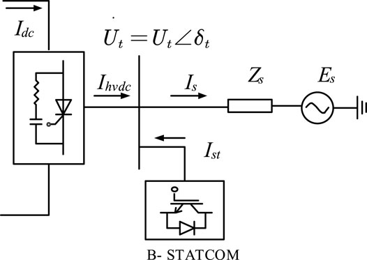
FIGURE 7. Schematic diagram of the LCC-HVDC receiving-end system with STATCOM/BESS.
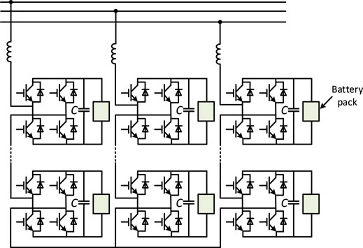
FIGURE 8. STATCOM/BESS topology.
For the convenience of analysis, taking the voltage phasor of the converter bus as the reference coordinate, (Shen et al., 2022) according to the circuit principle, the voltage coordinates of each phase of the converter bus can be obtained when the system is in stable operation (assuming that STATCOM/BESS does not output reactive current at this time):
Ut0 represents the steady-state phasor before fault, and U represents the voltage amplitude before fault. According to Eq. 9, the commutation voltages corresponding to the converter valves are:
When the A-phase short-circuit fault occurs in the AC system at the receiving end, the phase voltage Uta of the converter bus becomes the original (1-d), (Yang et al., 2019) and the reactive current output by STATCOM is Ist = Istp + Istn, where Istp and Istn are positive and negative reactive currents, respectively. Assuming that the phasor of positive and negative sequence reactive current is perpendicular to the phasor of converter bus voltage, the positional relationship of Istp and Istn is shown in Figure 9.
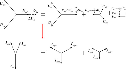
FIGURE 9. Schematic diagram of decomposition of positive and negative sequence reactive current.
The corresponding commutation voltage is Yang et al. (2022):
By substituting Eq. 11 into the calculation formula of the extinction angle, the extinction angle of each converter valve after STATCOM/BESS that compensates positive and negative reactive power is:
where m = (ab,bc,ca), in which Xt represents the reactance of the commutation transformation phase, δtm represents the voltage phase after fault, and δtm0 represents the voltage phase before fault (Yang et al., 2021a).
The reference capacity SB of the LCC-HVDC system with STATCOM/BESS is taken as 1000 MVA; the reference voltage VB is taken as 230 kv, and the rated power of STATCOM/BESS is taken as 100 MVA. Xun and Pongsathorn (2021) In order to prevent reactive power compensation equipment from burning out due to over-current, the output current of each phase of STATCOM/BESS should not exceed its rated current. According to Figure 9, the output current of STATCOM/BESS needs to meet the following constraints:
In the formula, Im is rated current of STATCOM/BESS and Im = 0.1p.u. According to Eq. 13, the feasible region of reactive current can be obtained as shown in the yellow area in Figure 10.
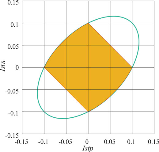
FIGURE 10. Feasible region of STATCOM/BESS output current.
Substituting the positive and negative sequence reactive current values in the feasible region into Eqs 12, 13 (Xun et al., 2017), it can be concluded that there is a larger positive gradient between the minimum value in the extinction angle of each converter valve and the positive sequence reactive current, that is, the positive sequence current compensated by STATCOM/BESS has a more obvious effect on increasing the extinction angle.
Therefore, after a single-phase grounding fault, (Shen et al., 2020a) in order to get better suppression effect of commutation failure, the compensation component of STATCOM/BESS positive sequence reactive current should be increased.
Simulation of Suppression Effect of Positive and Negative Sequence Reactive Power Compensation Components on Commutation Failure
In order to verify the theoretical analysis in Section 3.1, (Shen et al., 2020b) this section compares the effects of STATCOM/BESS on suppressing commutation failure under different positive and negative sequence reactive current compensation ratios based on the CIGRE HVDC standard test model. Starting from 1.0 s, the A-phase-inductive grounding fault is set at the inverter side converter bus at 1 ms intervals so as to simulate the single-phase fault at different closing angles of the receiving-end power grid in practical engineering. Yang et al. (2018) When STATCOM/BESS compensates the positive and negative sequence currents by 1:1, 2:1, and 1:0, respectively, after detecting the fault (the sum of the positive and negative sequence output currents is 0.1pu), the critical inductance value of commutation failure of the inverter station is shown in Table 2. In Table 2, when the fault occurs at the same time, the green frame to the red frame sequentially indicate that the critical fault inductance gradually increases, that is, the commutation failure suppression effect gradually weakens. With the increase of the proportion of positive sequence reactive power commands, the number of green frames gradually increases, indicating that the commutation failure suppression effect is enhanced, (Zhu et al., 2020) which is consistent with the theoretical analysis in Section 3.1.
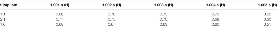
TABLE 2. Comparison of commutation failure suppression effects.
STATCOM/BESS Simulation Experiment
Figure 11 shows the LCC-HVDC standard model with STATCOM/BESS built in this article. The rectifier converter station and inverter converter station contain high and low valve sets, respectively. The rated DC voltage of the CIGRE HVDC model is ±500 kV, and the rated transmission capacity is 1000MW. Other main circuit parameters are shown in Table 3.
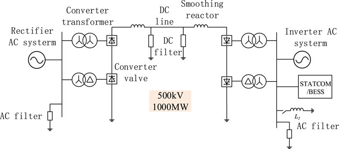
FIGURE 11. LCC-HVDC standard model with STATCOM/BESS.

TABLE 3. Main parameters of the CIGRE HVDC model simulation circuit.
The control system adopts double-loop control, in which the inner loop is current control and the outer loop reactive power control can be selected as constant AC voltage control and constant reactive power control, and the active control part can be selected as active control or constant DC voltage control. The control block diagram is shown in Figure 12.
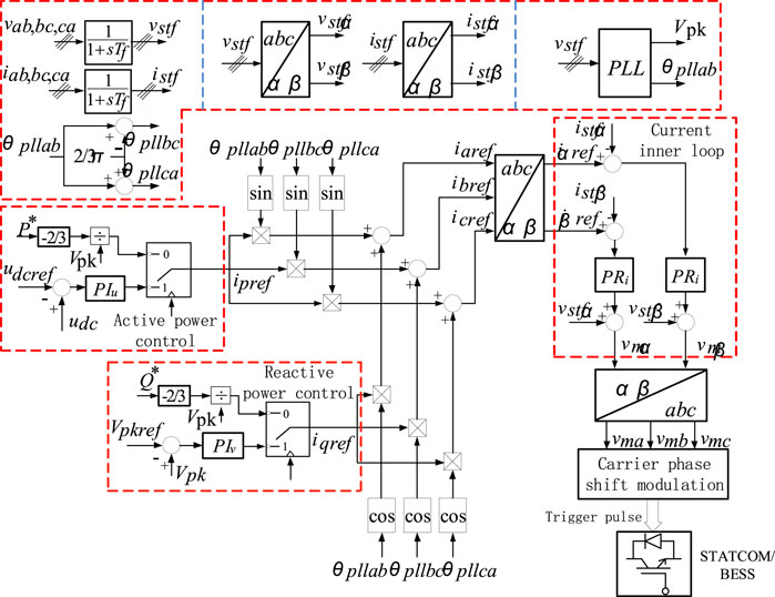
FIGURE 12. Control structure of the three-module angle chain energy storage STATCOM.
In order to compare the commutation failure suppression effect between STATCOM/BESS and conventional STATCOM, a serious single-phase grounding fault is set at 1s in this experiment. Figure 13A and Figure 13B show the AC voltage and inverter current at the inverter side of the HVDC system when a A-phase at the inverter side suddenly has a grounding fault after a period of normal operation. At this time, the system is equipped with conventional STATCOM. After the fault occurred, the A-phase voltage begin to drop, and the AC voltage on the inverter side is greatly distorted. The inverter current dropped to 0 at the same time in the vicinity of 1s, indicating that commutation failure occurred.
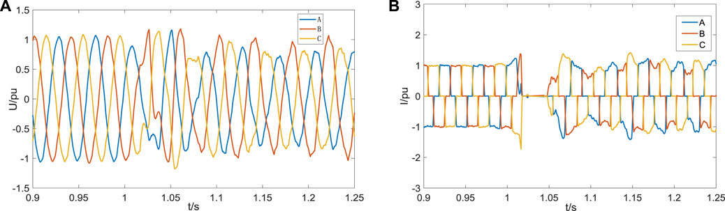
FIGURE 13. Simulation waveform diagram after installing conventional STATCOM. (A) AC voltage on the inverter side; (B) inverter current of the converter valve.
When STATCOM/BESS is installed in the system, the grounding fault occurs in A-phase in 1s. It can be seen from Figure 14A and Figure 14B that the AC voltage distortion on the inverter side is relatively small, and the phenomenon that the three-phase current is zero at the same time during the fault period does not occur, which indicates that STATCOM/BESS has restrained the occurrence of commutation failure under the single-phase fault condition.
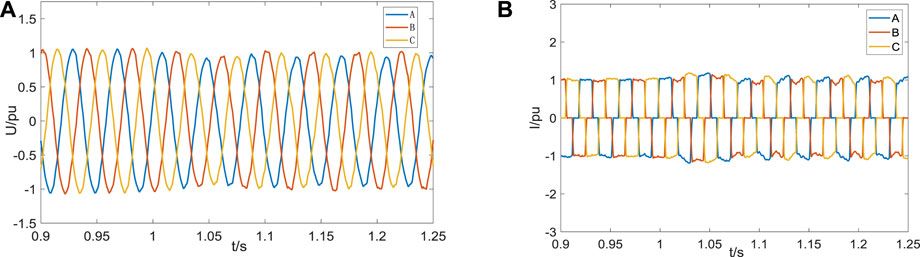
FIGURE 14. Experimental waveform diagram of installing STATCOM/BESS. (A) AC voltage on the inverter side; (B) inverter current of the converter valve.
Comparing the extinction angle and system transmission power under the two conditions; it can be seen from Figure 15A that the extinction angle drops to 0 after the fault occurs when installing conventional STATCOM and never drops below 10 after installing STATCOM/BESS, which effectively inhibits the commutation failure at the inverter side. It can be seen from Figure 15B that STATCOM/BESS compensates active power and reactive power at the same time in case of failure. Compared with conventional STATCOM, the transmission power oscillation of the system is smaller, which can quickly stabilize the transmission of system power in case of failure.
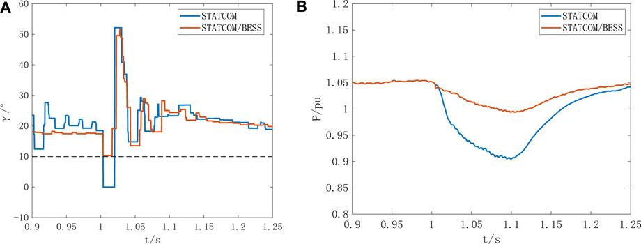
FIGURE 15. Comparison diagram of the system transmission power and extinction angle. (A) Comparison diagram of extinction angle; and (B) Comparison diagram of transmission power.
Conclusion
The purpose of this article is to suppress commutation failure at the weak receiving end of the LCC-HVDC system and propose a compensation method for STATCOM/BESS to suppress commutation failure under the single-phase grounding fault. The design and comparison simulation verify the ability of STATCOM/BESS to suppress commutation failure and draw the following conclusions:
(1) Under the single-phase grounding condition of the AC system on the inverter side, the commutation failure conditions of each phase of the converter valve are different.
(2) Increasing the proportion of the positive sequence reactive power compensation component of STATCOM/BESS output under the single-phase grounding fault of the AC system on the inverter side can better restrain commutation failure.
(3) The STATCOM/BESS device is installed in the single-pole 12-pulse HVDC transmission system, and a single-phase ground fault was set, and a comparison experiment was carried out with the traditional STATCOM system; by comparing the four typical electrical quantities of AC voltage, inverter current, turn-off angle, and system transmission power, which verifies the effectiveness of the STATCOM/BESS designed in this article in suppressing commutation failure.
Data Availability Statement
The original contributions presented in the study are included in the article/Supplementary Material, further inquiries can be directed to the corresponding author.
Author Contributions
CX was responsible for providing ideas and methods and providing an experimental platform. SC was responsible for deriving formulas, reviewing, and verifying. JC was responsible for model building, simulation, data analysis, and manuscript writing. All authors participated in the reading and approved the submitted version.
Funding
The research is funded by the National Natural Science Foundation of China (52067009).
Conflict of Interest
Authors CX, JC, ZX, XX, and XH were employed by the Electric Power Research Institute of Yunnan Power Grid Co., Ltd.
The remaining author declares that the research was conducted in the absence of any commercial or financial relationships that could be construed as a potential conflict of interest.
Publisher’s Note
All claims expressed in this article are solely those of the authors and do not necessarily represent those of their affiliated organizations, or those of the publisher, the editors, and the reviewers. Any product that may be evaluated in this article, or claim that may be made by its manufacturer, is not guaranteed or endorsed by the publisher.
References
Cai, W., Yang, G., Du, D., and Wang, X. (2019). Commutation Failure Prediction and Identification Method Considering Multiple Factors. Power Syst. Technology. 43 (10), 3477–3487. doi:10.13335/j.1000-3673.pst.2019.1098
Guo, C., Zhang, Y., and Zhao, C. (2013). Influence of STATCOM on the Operating Characteristics of Dual-Infeed DC Systems. Proc. Chin. Soc. Electr. Eng. 33 (25), 99–106. doi:10.13334/j.0258-8013.pcsee.2013.25.006
Guobing, S., Junjie, H., and Bing, G. (2020). Pilot protection of Hybrid MMC DC Gridbased on Active Detection. Prot. Control. Mod. Power Syst. V5 (1), 82–96. doi:10.13335/j.1000-3673.pst.2020.0200a
He, J., Chen, K., and Li, M. (2020). Review of protection and Fault Handling for a Flexible DC Grid. Prot. Control. Mod. Power Syst. 5 (1), 15. doi:10.1186/s41601-020-00157-9
Huang, Y. (2006). Research on Commutation Failure of HVDC transmission[D]. Beijing: North China Electric Power University.
Le, S., Wu, Y., Guo, Y., and Vecchio, C. D. (2021). Game Theoretic Approach for a Service Function Chain Routing in NFV with Coupled Constraints. IEEE Trans. Circuits Syst. 68, 3557–3561. Published online. doi:10.1109/TCSII.2021.3070025
Lei, Z., Yumiao, X., and Jing, Y. (2021). Intelligent Frequency Control Strategy Based on Reinforcement Learning of Multi-Objective Collaborative Reward Function. Front. Energ. Res. Early Access 9. doi:10.3389/fenrg.2021.760525
Li, Z., Wang, J., Li, Y., Wang, Z., Huang, M., and Fu, C. (2017). Modeling of Switching Function of HVDC Converter Based on the Zero Crossing point of Actual Commutation Voltage. Proc. Chin. Soc. Electr. Eng. 37 (18), 5389–5398+5538. doi:10.13334/j.0258-8013.pcsee.161788
Liang, S. (2014). Research on Static Synchronous Compensator with Battery Energy Storage device[D]. Harbin: Harbin Institute of Technology.
Mitsuru, T., and Yuhu, W. (2021). Mayer-Type Optimal Control of Probabilistic Boolean Control Network With Uncertain Selection Probabilities. IEEE Trans. Cybernetics. 51, 3079–3092. doi:10.1109/TCYB.2019.2954849
Mohan, M. (2021). A Comprehensive Review of DC Faultprotection Methods in HVDC Transmissionsystems. Prot. Control. Mod. Power Syst. V6 (1), 1–20.
Muniappan, S. (2021). A Comprehensive Review of DC Fault protection Methods in HVDC Transmission Systems. Singapore: Singapore Springer Pte Ltd.
Peng, L., He, J., and Xie, K. (2017). Comparison of Reliability and Economy of UHVAC and DC Transmission Systems. Power Syst. Technology. 41 (4), 1098–1107. doi:10.13335/j.1000-3673.pst.2016.2503
Shen, X., Ouyang, T., Khajorntraidet, C., Li, Y., Li, S., and Zhuang, J. (2022). Mixture Density Networks-Based Knock Simulator. Ieee/asme Trans. Mechatron. 27, 159–168. doi:10.1109/TMECH.2021.3059775
Shen, X., Ouyang, T., Yang, N., and Zhuang, J. (2021). Sample-based Neural Approximation Approach for Probabilistic Constrained Programs. IEEE Trans. Neural Netw. Learn. Syst., 1–8. doi:10.1109/TNNLS.2021.3102323
Shen, X., and Raksincharoensak, P. (2021). Pedestrian-aware Statistical Risk Assessment. IEEE Trans. Intell. Transport. Syst., 1–9. doi:10.1109/TITS.2021.3074522
Shen, X., Zhang, X., Ouyang, T., Li, Y., and Raksincharoensak, P. (2020a). Cooperative Comfortable-Driving at Signalized Intersections for Connected and Automated Vehicles. IEEE Robot. Autom. Lett. 5 (4), 6247–6254. doi:10.1109/LRA.2020.3014010
Shen, X., Zhang, Y., Sata, K., and Shen, T. (2020b). Gaussian Mixture Model Clustering-Based Knock Threshold Learning in Automotive Engines. Ieee/asme Trans. Mechatron. 25 (6), 2981–2991. doi:10.1109/TMECH.2020.3000732
Virtanen, A., Tuusa, H., and Aho, J. (2013). “Performance Analysis of Conventional STATCOMs and STATCOMs with Energy Storage in Electric Arc Fumace Applications,” in 28th Annual IEEE Applied Power Electronics Conference and Exposition, Long Beach. USA, 1623–1629.
Xun, S., and Pongsathorn, R. (2021). Statistical Models of Near-Accident Event and Pedestrian Behavior at Non-signalized Intersections. J. Appl. Stat. doi:10.1080/02664763.2021.1962263
Xun, S., Yahui, Z., Tielong, S., and Chanyut, K. (2017). Spark advance Self-Optimization with Knock Probability Threshold for Lean-Burn Operation Mode of SI Engine. Energy. 122, 1–10. doi:10.1016/j.energy.2017.01.065
Yang, N., Huang, Y., and Hou, D. (2019). Adaptive Nonparametric Kernel Density Estimation Approach for Joint Probability Density Function Modeling of Multiple Wind Farms. Energies 12, 1356. doi:10.3390/en12071356
Yang, N., Ye, D., Zhou, Z., Cui, J., Chen, D., and Wang, X. (2018). Research on Modelling and Solution of Stochastic SCUC under AC Power Flow Constraints. IET Generation, Transm. Distribution. 12 (15), 3618–3625. doi:10.1049/iet-gtd.2017.1845
Yang, N. (2021). A Comprehensive Review of Security-Constrained Unit Commitment. J. Mod. Power Syst. Clean Energ. doi:10.35833/MPCE.2021.000255
Yang, N., Liu, S., Deng, Y., and Xing, C. (2021a). An Improved Robust SCUC Approach Considering Multiple Uncertainty and Correlation. IEEJ Trans. Elec Electron. Eng. 16, 21–34. doi:10.1002/tee.23265
Yang, N., Yang, C., Xing, C., Ye, D., Jia, J., Chen, D., et al. (2021b). Deep Learning‐based SCUC Decision‐making: An Intelligent Data‐driven Approach with Self‐learning Capabilities. IET Generation Trans. Dist 16, 629–640. doi:10.1049/gtd2.12315
Yang, N., Yang, C., Wu, L., Shen, X., Jia, J., Li, Z., et al. (2022). Intelligent Data-Driven Decision-Making Method for Dynamic Multisequence: An E-Seq2Seq-Based SCUC Expert System. IEEE Trans. Ind. Inf. 18, 3126–3137. doi:10.1109/TII.2021.3107406
Yu, X., Wang, Y., Zhang, Q., Wang, Y., Dong, Y., and Gan, Z. (2020). Power Transfer Strategy of Parallel Three-Terminal Hybrid UHVDC Transmission System. Automation Electric Power Syst. 44 (23), 150–156. doi:10.7500/AEPS20200601004
Yuhu, W., Yuqian, G., and Toyoda, M. (2021). Policy Iteration Approach to the Infinite Horizon Average Optimal Control of Probabilistic Boolean Networks. IEEE Trans. Neural Networks Learn. Syst. 32 (6), 2910–2924.
Zhang, Y. (2011). Investigation of Reactive Power Control and Compensation for HVDC system[D]. Winnipeg: The University of Manitoba.
Zhao, T., Lu, M., and Lou, J. (2015). Research on Abnormal Commutation Failure of Multi-Feed HVDC Transmission System. Power Syst. Technology. 39 (3), 705–711. doi:10.13335/j.1000-3673.pst.2015.03.018
Zhenhua, L., Weihui, J., and Abu-Siada, A. (2021). Research on a Composite Voltage and Current Measurement Device for HVDC Networks. IEEE Trans. Ind. Electronics 69 (9), 8930–8941. doi:10.1109/TIE.2020.3013772
Zhu, B., Ding, F., and Vilathgamuwa, D. M. (2020). Coat Circuits for DC-DC Converters to Improve Voltage Conversion Ratio. IEEE Trans. Power Electron. 35 (4), 3679–3687. doi:10.1109/TPEL.2019.2934726
Keywords: high voltage direct current (HVDC) transmission, battery energy storage STATCOM, commutation failure, positive and negative sequence reactive current, single-phase grounding fault
Citation: Xing C, Chen J, Xu Z, Xi X, He X and Chen S (2022) Research on Battery Energy Storage STATCOM Suppressing HVDC Commutation Failure. Front. Energy Res. 10:865620. doi: 10.3389/fenrg.2022.865620
Received: 30 January 2022; Accepted: 14 February 2022;
Published: 24 March 2022.
Edited by:
Xun Shen, Tokyo Institute of Technology, JapanReviewed by:
Hardeep Singh, Sophia University, JapanVarun Nayyar, Lovely Professional University, India
Copyright © 2022 Xing, Chen, Xu, Xi, He and Chen. This is an open-access article distributed under the terms of the Creative Commons Attribution License (CC BY). The use, distribution or reproduction in other forums is permitted, provided the original author(s) and the copyright owner(s) are credited and that the original publication in this journal is cited, in accordance with accepted academic practice. No use, distribution or reproduction is permitted which does not comply with these terms.
*Correspondence: Shilong Chen, Y2hlbnNoaWxvbmczQDEyNi5jb20=