 Chunmin Guan1
 Wenke Zhang
- 1School of Thermal Engineering, Shandong Jianzhu University, Jinan, China
- 2Shandong Zhongrui New Energy Technology Co. Ltd, Jinan, China
The U-type medium-deep borehole ground heat exchanger BGHE is a new form of utilization of geothermal energy and there has been relatively little research on it. This paper introduces the structure and working principle of the BGHE. The energy control equations based on the characteristics of the heat transfer model are established creatively. The initial and boundary conditions of the circulating fluid and rock soil are determined. And the reliability of the simulation is verified through comparing the simulated results with the engineering data. Based on the above theoretical foundation, the effects of the circulating fluid flow rate, geothermal gradient and thermal conductivity of different soil layers on the nominal heat extraction and the outlet temperature of the U-type BGHE are examined. The temperature changes in the soil surrounding the vertical pipe and the temperature of circulating fluid at the inlet and outlet of the BGHE are analysed. The corresponding reasons of these changes are revealed. It is shown from simulation results that the circulating fluid flow rate has opposite influence on the nominal heat extraction and outlet temperature. The increasing terrestrial heat flow is conducive to heat transfer, but the reverse heat transfer occurs during the heat transfer process. The influence of the BGHE on the surrounding rock soil will hardly affect the continuous use of the buried ground heat exchanger. The results of the study are beneficial to better understand the heat transfer characteristics of the U-type medium-deep BGHE and its impact on the surrounding soil. It will promote the popularization and application of medium-deep geothermal energy.
1 Introduction
The concept of the ground source heat pump (GSHP) was first proposed by Zoelly of Switzerland in 1912, and it has become a pertinent research focus (Manzella et al., 2018; Luo et al., 2020; Zheng et al., 2021). The GSHP, as a new energy extraction technique, by consuming a small part of electric energy, extracting heat from the ground or discharging heat into the ground to achieve the purpose of heating or cooling the building (Cai et al., 2022). It has the capability to provide a renewable source of energy and help reducing greenhouse gas emissions. It is environmentally friendly, energy saving and high-efficiency (Chu and Dong, 2021; El Haj Assad et al., 2021; Fan et al., 2022). The energy stored in the depth of 50–200 m is usually called shallow geothermal energy. At present, the application of shallow geothermal energy has been relatively extensive (Li et al., 2019). However, in areas with a dominant heat load or only a heat load, It is difficult to meet the heating demand by using shallow geothermal energy (Sarbu and Sebarchievici, 2014; Luo et al., 2022).
Considering the above limitation of the application of SBHE, medium-deep geothermal energy is developing rapidly and increasingly popular (Li et al., 2021). The medium-deep geothermal energy is stored in soil at a depth of 1000–3000 m. It is utilized by arranging medium-deep BGHEs (Deng et al., 2020; Du and Man, 2020). The BGHEs can be classified as direct heat exchangers and indirect heat exchangers. The enhanced geothermal system is a more mature form of direct heat exchange (Olasolo and Juárez, 2016; Liu et al., 2019a). However, the long-term use of direct heat exchangers causes changes in geological structures (Jiao and Yang, 2022), and problems such as insufficient groundwater recharge and potential pollution risks. The indirect heat exchange method uses a closed heat exchanger with water as the circulating medium (Liang, 2018). Compared to direct heat exchangers, indirect heat exchangers effectively protect water resource. In the application of indirect medium-deep BGHEs, some projects use pipe-in-pipe heat exchangers (Liu et al., 2019b). The outer pipe is usually a steel pipe, which has a high thermal conductivity and plays a supporting and fixing role. The inner pipe is a plastic pipe with a low thermal conductivity to preserve heat. The circulating fluid in the coaxial BGHE flows from the outer pipe into the inner pipe or inverse. Some researchers have also carried out simulations on the types of flowing media in the pipe (He et al., 2021).
To more efficiently apply medium-deep geothermal energy to meet the heating requirements of large building areas, a new type of underground heat exchanger is considered, which reaches depths of 1,000–3,000 m. The two vertical boreholes are connected horizontally at the bottom, and steel pipes are arranged in these boreholes to form a U-type medium-deep BGHE, which consists of descending borehole, horizontal borehole, ascending borehole, descending pipe, horizontal pipe, ascending pipe and backfill material between the boreholes and corresponding pipes. Circulating fluid flows in the descending pipe, passes through the descending, horizontal and ascending pipes sequentially, and then flows out of the ascending pipe. A schematic diagram of the BGHE is shown in Figure 1.
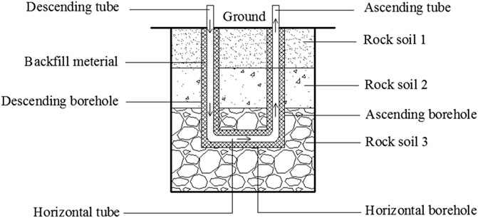
FIGURE 1. Diagram of the U-type medium-deep BGHE.
When it is compared with the coaxial medium-deep BGHE, the horizontal tube buried at the bottom of the borehole can exchange more heat. In 2016, Shanxi Coal Field Geology Group Company completed the first U-type well docking project in China (Zhang et al., 2020), and adopted a closed unidirectional circulation. Zhou Cong et al. monitored the outlet temperature of the U-type BGHE in real time under the conditions of constant water inlet temperature and water flow rate in the buried pipe. And pointed out through analysis that the increase of the depth of the buried pipe has a greater impact on the heat transfer strength (Zhou et al., 2019). Zhang wenke et al. compared the heat extraction of U-type and coaxial BGHE, the results show that the heat extraction capacity of the U-type BGHE is better (Zhang et al., 2021). The medium-deep U-type BGHE is a new form application of geothermal energy. At present, there is little research on it. In this paper, heat transfer models of the medium-deep U-type BGHE are established creatively, and the corresponding prerequisites are described. When it is compared with the SBHEs, the geothermal gradient must be considered due to the large depth. The influence of the flow rate, the terrestrial heat flow and the thermal conductivity of the soil on the nominal heat extraction and outlet temperature of the U-type medium-deep BGHE are analyzed. Moreover, because of the large borehole depth, the construction is more difficult, and the drilling cost will be relatively high. If the heat transfer performance of this underground heat exchanger and heat transfer influences on the surrounding soil can be revealed, this will be beneficial to better understand this BGHE. Therefore, the temperature changes in the vertical pipe and surrounding soil, and the temperature of the circulating fluid inlet and outlet are both simulated and analysed, which may further promote the popularization and application of medium-deep geothermal energy.
2 Project Overview
The ground heat exchangers (GHEs) and heat pumps are the essential parts of the.
Ground source heat pump systems (He and Feng, 2001), and a schematic diagram of the whole system is shown in Figure 2.
1. Descending tube 2. Rock soil layer 1) 3. Rock soil layer 2) 4. Rock soil layer 3) 5. Descending borehole 6. Horizontal tube 7. Horizontal borehole 8. Ascending borehole 9. Backfill material 10. Ascending tube 11. Ground 12. Flowmeter 13. Thermometer 14. Valve 15. Valve 16. Thermometer 17. Water pump 18. Thermometer 19. Flowmeter 20. Indoor end equipment 21. Room 22. Water pump 23. Thermometer 24. Valve 25. Heat pump unit 26. Valve
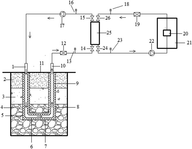
FIGURE 2. Diagram of the GSHP system employing the U-type medium-deep.
Borehole Ground Heat Exchanger
The depth of the U-type medium-deep BGHE is 1800 m, and the borehole diameter is 300 mm. The length of the horizontal borehole is 350 m. Steel pipes are arranged in the boreholes. The outer diameter of the tubes is 220.5 mm, and the inner diameter is 200 mm. The thermal conductivity of the steel tubes is 48 W/mK, and the volumetric heat capacity is 3.4 × 10⁶ J/(m3·K). Cement with an average thermal conductivity of 2.5 W/mK and a volumetric heat capacity of 2.6 × 10⁶ J/(m3·K) is backfilled between the pipes and boreholes.
The rock soil surrounding the U-type medium-deep BGHE includes three strata, and the relevant information is listed in Table 1.
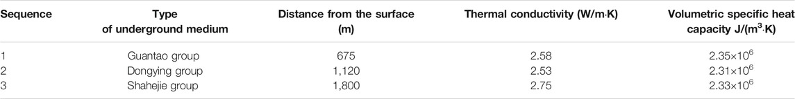
TABLE 1. Parameters of the soil medium.
During the drilling process, the first step is completing the drilling of the vertical boreholes. Then, to ensure the smooth docking of the two boreholes, it is necessary to perform a multi-point measurement and import it into a unified measurement system with the well trajectory. During the connection construction process, the magnetic launch device is inserted into one of the vertical boreholes, the measurement probe is inserted into the other vertical borehole, and the real-time received signal is fed back to the control system to adjust the position of the drill bit to smoothly penetrate the horizontal borehole section. The heat exchange steel pipes are put into the borehole in sections, and threaded connections are used to connect each section of the steel pipe. A vertical pipe composed of several sections of steel pipes is put in one of the vertical boreholes, and the other steel pipe is put in the other borehole. Due to the deep drilling depth, the bottom of the steel pipes will automatically bend along the direction of the horizontal drilling after being stressed. Finally, it is positioned and connected at the bottom of the vertical borehole with the vertical pipeline previously put.
3 Heat Transfer Models
3.1 Basic Assumptions
The U-type medium-deep BGHE is composed of descending pipe, horizontal pipe, and ascending pipe. The circulating fluid flows in from the descending pipe, through the horizontal pipe, and finally flows out of the ascending pipe. Establishing and solving the heat transfer model needs to consider the physical conditions of the heat exchanger and surrounding soil. The borehole is very deep and will pass through multiple soil strata, so it is necessary to independently count the parameter information of each stratum soil medium. The temperature at the bottom of the borehole can reach 60°C or even higher, and the heat is transferred from the underground to the ground through heat conduction. The geothermal gradient in the depth direction cannot be ignored. It is also an important factor in the analysis of the heat transfer of the soil. Therefore, the entire heat transfer process is complicated. In order to facilitate exploration and research, some situations can be simplified through basic assumptions.
1) Only heat conduction is considered in the rock soil heat transfer mechanism.
2) The rock soil layer is considered to be a homogeneous medium or a uniformly layered medium within the scope under investigation. The physical properties of the medium do not change with the temperature, and the effect of groundwater seepage is not considered.
3) The heat transfer processes in the surrounding rock and the soil around the descending, horizontal and ascending boreholes do not affect each other within the studied time range.
4) The convective heat transfer between the air and the ground is considered, and the convective heat transfer coefficient is remain unchanged, and the air temperature above the ground is set as the local annual average temperature.
5) The heat exchanger has no leakage and other mass exchange, and the flow rate of the circulating fluid in the three pipe sections is the same.
3.2 Governing Equations
3.2.1 Energy Equations of the Rock Soil
Taking the three heat exchange pipes as the center, and establishing a cylindrical coordinate system respectively, where the z-axis is the axial direction and the r-axis is the radial direction. The energy equation of the rock soil is expressed as Eq. 1[22]:
Considering that the temperature gradient in the radial central part is high and that in the edge part is low in cylindrical coordinates, unequal differential step lengths can be adopted in the radial direction. The above equation is changed as follows:
where α is the thermal diffusion coefficient of the underground medium, r and z are the radial and vertical coordinates, respectively, τ is the time, and T (r,z,τ) is the temperature distribution function, r0 is the radius of the borehole.
3.2.2 Energy Equations of the Circulating Fluid
Take the fluid flow and heat transfer in the U-type pipe as a one-dimensional problem. m is the mass flow rate of the fluid in the tube, kg/s, and c is the specific heat capacity, kJ/kgK. The energy equation of the fluid in the pipes is Equation 4[22] (subscripts 1, 2 and 3 denote the descending, horizontal and ascending pipes, respectively):
Where Tbn(z,τ) is the temperature of the borehole walls °C. Tfn (z,τ) is the temperature of the fluid in the pipes, °C. Cn is the sum of the heat capacity of the various materials in the BGHE per unit length of each pipe section. The calculation equation is:
where dbn is the drilling diameter of the borehole. dno and dni are the outer and inner diameters of the pipe, respectively. ρwcw, ρncn and ρgcg are the volumetric specific heat capacities of water, pipes and backfill material, respectively. Rn is the thermal resistance per unit length between the fluid in the pipe and the corresponding borehole wall. Their expression is as follows:
where λpn is the thermal conductivity of the pipe. λgn is the thermal conductivity of the backfill material. hn is the convective heat transfer coefficient between the fluid in the pipe, respectively, and the inner wall of the pipe. The fluid flow in the pipe belongs to forced convection heat transfer. The minimum Reynolds number for fluid flow in the three pipes is 26889. The fluid flow is turbulent and the equations are as follows:
λ is the thermal conductivity of the fluid. un is the flow rate of the fluid in the pipe. ν is the kinematic viscosity of the fluid. α’ is the thermal diffusion coefficient of the fluid.
3.3 Initial and Boundary Conditions
3.3.1 Initial and Boundary Conditions of the Underground Medium
The initial temperature of the surrounding soil of the U-type medium-deep BGHE is uniformly distributed along the radial direction, and there is a temperature gradient in the depth direction and a uniform upward terrestrial heat flow in the rock soil. Initial conditions (τ = 0):
In the process of heat transfer analysis of the BGHE, there are three boundaries. They are the ground surface and the rock soil which is far enough in the radial and axial direction, respectively. At the surface of the ground, there will be convection heat transfer between the rock soil and the nearby air, which can be regarded as the third type of boundary condition. At the same time, it is assumed that the temperature of the rock soil which is far enough in the radial and axial direction is not affected by the borehole heat exchanger. Therefore, the radially and axially far enough apart can be regarded as adiabatic boundary conditions.
H is the depth of the U-type medium-deep BGHE. T(z) is the initial temperature at any depth in rock and soil. Ta is the air temperature above the ground. qg is the terrestrial heat flow. The terrestrial heat flow refers to the energy transferred from the center of the earth to the outside, that is, the heat flowing through a unit area of the earth’s surface per unit time. λs is the thermal conductivity of the soil.
3.3.2 Initial and Boundary Conditions of the Circulating Fluid
The initial temperature of the fluid in the descending, horizontal and ascending pipes of the U-type medium-deep BGHE is the same, and it equals the initial temperature of the surrounding soil at the same depth.
Initial conditions (τ = 0):
Boundary conditions (τ
where t’f1 and t’’f1 are the inlet and outlet temperature, respectively, of the circulating fluid in the descending pipe, t’f2 and t’’f2 are the inlet and outlet temperature, respectively, of the circulating fluid in the horizontal pipe, t’f3 and t’’f3 are the inlet and outlet temperature, respectively, of the circulating fluid in the ascending pipe, Q is the heat load of the BGHE, and Cw (J/(kgK)) is the mass specific heat capacity of the circulating fluid.
4 Results and Discussion
The simulation was programmed and analyzed in Fortran language. The forward difference method is used to establish the energy node equations for the circulating fluid in the pipes and the surrounding soil. The number of radial nodes is 40, the step length magnification is 1.2 times, and the radial boundary is approximately 338.05 m from the centre. The discrete step in the depth direction is 10 m, the boundary is 100 m from the bottom of the borehole, and the time step is 1 h.
The local atmosphere annual average temperature is 13°C and the surface convective heat transfer coefficient is 15 W/(m2·K) (He and Feng, 2001). The BGHE operates from November 15 to March 15 of the following year.
4.1 Verification
The actual project runs continuously under multiple working conditions during operation, and the 240–720 h is the same as the simulated working conditions in this paper. When the simulation conditions are the same as the actual working conditions, this simulation analyzes the outlet temperature of the U-type medium-deep BGHE after 720 h of operation, and compares the 240–720 h data with the actual data (The inlet temperature is fixed at 10.5°C, and the flow rate is 11.11 kg/s). The result is shown in Figure 3:
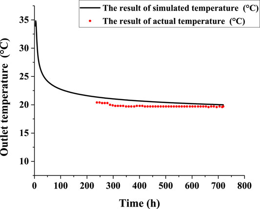
FIGURE 3. The comparison of simulation and actual data.
The variation trend between the simulation results and the actual results is basically the same, indicating that the simulation results have extremely good fitting degree with the engineering data. The maximum error between simulated and actual data is 5.89%, indicating that the model and the boundary conditions established in this paper is reliable and the simulation can be used to analyze the heat transfer performance of the U-type medium-deep BGHE.
4.2 Research on Nominal Heat Extraction and the Outlet Temperature
The nominal heat extraction is a virtual quantitative index determined via simulation. This index is conveniently conveyed by engineers to non-professionals. It is defined as the maximum heat extraction provided by the U-type medium-deep BGHE under certain operating conditions. These specific working conditions are as follows:
1) Constant heat extraction occurs over 3 months (90 days).
2) The initial temperature distributions of the various rock soil layers are predetermined. Here, we assume that the rock soil layers are not disturbed by the U-type medium-deep BGHE system at the beginning of heat collection.
3) The inlet temperature of the BGHE system is not lower than 5°C during the entire heat extraction period.
4.2.1 Flow Rate
To examine the effect of the flow rate in the pipe on the nominal heat extraction and outlet temperature, based on a U-type well project, in this paper, only the circulating fluid flow of the BGHE is varied. The simulation result at a flow rate ranging from 50 to 120 m3/h is shown in Figure 4.
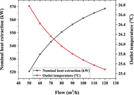
FIGURE 4. Nominal heat extraction and the outlet temperature at different flow rates.
With increasing flow rate of the circulating fluid, the nominal heat extraction of the U-type medium-deep BGHE gradually increases, but the increase remains small. At the same time, with increasing flow rate of the circulating fluid, the outlet temperature of the U-type medium-deep BGHE gradually decrease. Thus that the flow rate of the circulating fluid does not need to be maximum. When the flow rate of the circulating fluid is too high, not only does heat extraction not substantially increase but the outlet temperature also decrease, and the power consumption of the water pump will also increase, which will undoubtedly decrease the operating COP of the system. Therefore, the flow rate of circulating fluid should be reasonably selected during the operation.
4.2.2 Terrestrial Heat Flow
Figure 5 shows the change in the nominal heat extraction and the outlet temperature of the U-type medium-deep BGHE when the terrestrial heat flow varies between 0.03 and 0.08 W/m2.

FIGURE 5. Nominal heat extraction and the outlet temperature at different terrestrial heat flow.
The nominal heat extraction and the outlet temperature of the U-type medium-deep BGHE increases almost linearly with increasing terrestrial heat flow. This reveals that the higher the terrestrial flow is, the more heat is transferred from the interior of the Earth to the surface per time and area. BGHE operation is better achieved, and the soil temperature is restored faster.
4.2.3 Different Formation Thermal Conductivities
The stratum thermal conductivity greatly impacts heat extraction when the soil around the U-type medium-deep BGHE is composed of multiple strata. In this simulation, there are three soil layers from top to bottom around the BGHE. Figure 6 shows the change in the nominal heat extraction and the outlet temperature when the thermal conductivity of a single layer changed (1,2,3 is the number of the soil layer).
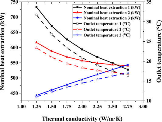
FIGURE 6. Nominal heat extraction under different thermal conductivities of a single soil layer.
Only by changing the thermal conductivity of the first soil layer does the nominal heat extraction and the outlet temperature of the U-type medium-deep BGHE gradually decrease with increasing thermal conductivity. When the circulating fluid enters the BGHE, it flows through the descending and horizontal pipes, and the temperature is high when it passes through the shallow soil in the process of flowing out of the ascending pipe, and reverse heat transfer occurs. The higher the thermal conductivity is, the more heat is lost by the circulating fluid, and the nominal heat extraction and the outlet temperature of the buried pipe heat exchanger is reduced. When the thermal conductivity of the second soil layer is varied, the nominal heat extraction and the outlet temperature of the BGHE still decreases with increasing thermal conductivity. This occurs because the reverse heat transfer phenomenon only occurs above a certain depth of this layer in the medium. Below this depth, an increase in the thermal conductivity is beneficial to the heat extraction of the BGHE, while an increase in the thermal conductivity above this depth adversely affects heat extraction and the outlet temperature. Under the combined effects of the above two phenomena, the nominal heat extraction and the outlet temperature exhibits a decreasing trend with increasing thermal conductivity, but the magnitude of the nominal heat extraction and the outlet temperature reduction of the second soil layer is smaller than that of the first soil layer. In actual engineering, an insulation layer can be set at a certain depth from the ground surface at the exit end of the U-type BGHE to reduce heat loss from reverse heat transfer. When the thermal conductivity of the third soil layer is altered, the nominal heat extraction and the outlet temperature of the BGHE increases with increasing thermal conductivity. With increasing soil depth, the temperature increases. Therefore, the circulating fluid absorbs more heat from the soil, and the corresponding nominal heat extraction and the outlet temperature increases.
4.3 Changes in Temperature of the Vertical Pipe and Surrounding Soil
4.3.1 Temperature Around and at the Bottom of the Vertical Pipe
The vertical pipes include descending and ascending pipes. The circulating fluid enters the U-type BGHE via the descending pipe, exchanges heat with the surrounding soil, and flows out of the ascending pipe. After 5 years of continuous operation, the temperature changes around and at the bottom of the vertical pipe are shown in Figure 7, where i is the radial distance from the descending or ascending tube and j is the depth.
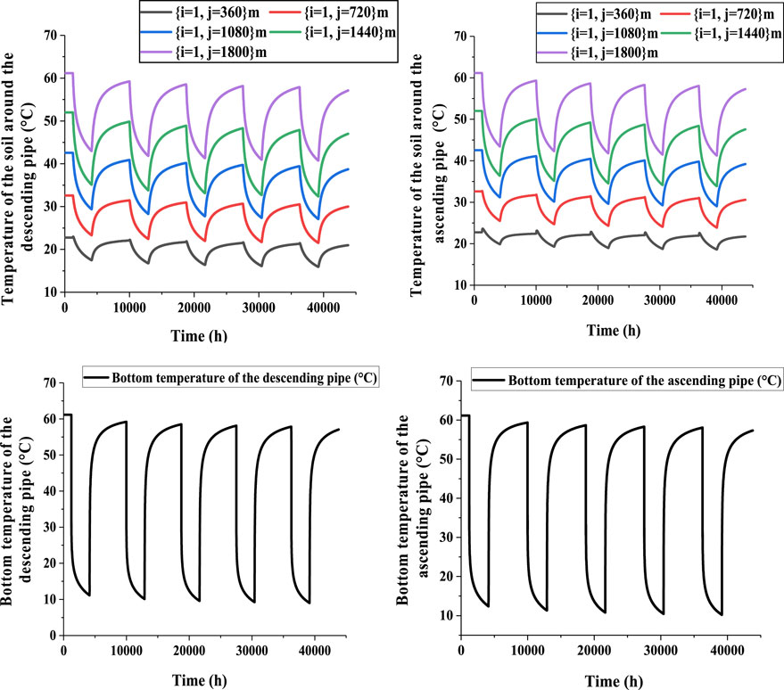
FIGURE 7. Changes in temperature around and at the bottom of the vertical pipe.
The temperature around and at the bottom of the vertical pipe changes periodically over time. During the heating season, the temperature around and at the bottom of the vertical pipe greatly decreases. During the non-heating season, the temperature around and at the bottom of the vertical pipe again increases. This indicates that the soil temperature is better restored during the non-heating period. However, the temperature around and at the bottom of the descending pipe is always slightly lower than that around and at the bottom of the ascending tube because the circulating fluid in the U-type medium-deep BGHE reaches the bottom of the descending tube and enters the horizontal pipe to exchange heat with the underground medium. It then reaches the ascending pipe and flows out of the BGHE. In this process, the temperature of the circulating fluid rises, and the temperature difference between the fluid and surrounding soil decreases, and the amount of heat absorbed from the soil decreases. Therefore, the temperature at the bottom and the surrounding soil of the ascending tube is relatively higher.
4.3.2 Soil Temperature Around the Vertical Pipe
This simulation studies the axial temperature distribution of the soil at different radial distances from the vertical pipe after 5 years of continuous operation of the U-type medium-deep BGHE. The distribution is shown in Figure 8.
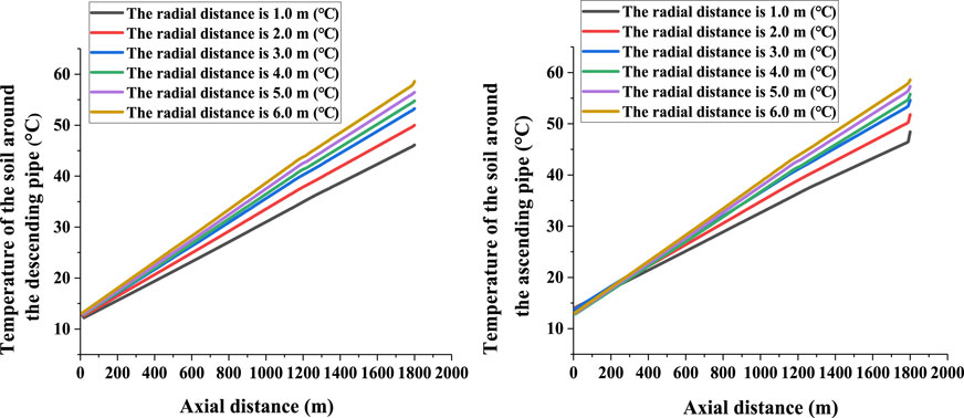
FIGURE 8. Axial distribution of the soil temperature around the vertical pipe.
When the radial distance remains constant, the soil temperature increases with the axial depth. When the axial distance remains unchanged, the soil temperature is high when the BGHE is far away because the soil far from the BGHE is less affected.
4.3.3 Isotherm Diagram of the Soil Around the Vertical Pipe
An isotherm diagram of the soil around the vertical pipe after 5 years of continuous BGHE operation is shown in Figure 9.
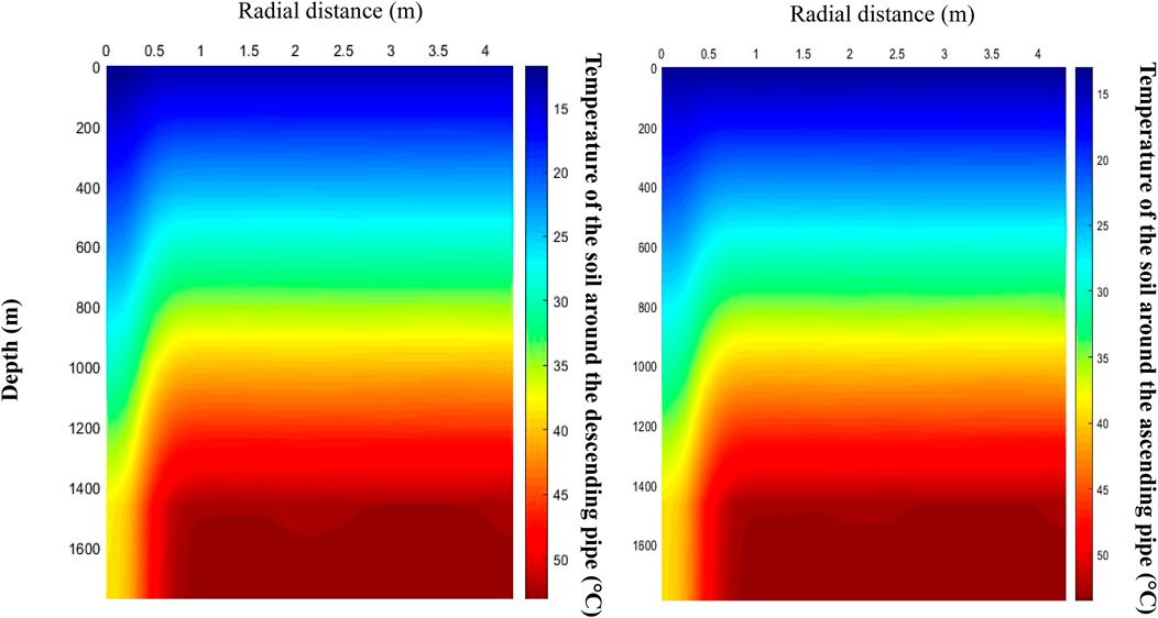
FIGURE 9. Isotherm diagram of the soil around the vertical pipe.
Figure 9 shows that the soil temperature increases with increasing soil depth, and the soil closer to the BGHE is more affected.
4.3.4 The Inlet and Outlet Temperatures Over Time
When the heat extraction is 500 kW,the temperature changes over time after 10 years of continuous operation of the BGHE are shown in Figure 10.
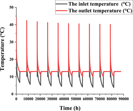
FIGURE 10. Change in inlet and outlet temperatures over time.
Over time, the maximum temperature at the outlet of the U-type medium-deep BGHE slowly decreases year by year, and almost do not change after the fifth year. It is still above 40°C in the 10th year, which reveals that the soil temperature can restore well during non-heating period. During system operation, the inlet temperature of the BGHE gradually decreases. If the BGHE extracts heat from the soil, the temperature of the surrounding soil will decrease. If the soil temperature remains unchanged, the temperature difference between the circulating fluid and soil decreases, and the original heat extraction level cannot be maintained. The basic stability of the heat extraction process is still ensured when the inlet temperature gradually decreases.
5 Conclusion
As a new form of utilization of geothermal energy, a BGHE can satisfy the heating demand of hundreds of square meters. However, little research has been done on this type of borehole heat exchanger. This paper established the energy control equations based on the characteristics of its heat transfer model creatively. Based on the theoretical analysis of the U-type medium-deep BGHE, certain factors influencing the nominal heat extraction and temperature changes in both the soil and circulating fluid are examined. We can draw the following conclusions:
4) The nominal heat extraction increases with increasing circulating fluid flow, but the outlet temperature of the U-type medium-deep BGHE gradually decrease. Thus that the flow rate of the circulating fluid does not need to be maximum.
5) The nominal heat extraction and the outlet temperature of the U-type medium-deep BGHE increases almost linearly with increasing terrestrial heat flow. This means that the BGHE will perform better in areas with high terrestrial heat flow.
6) The nominal heat extraction and outlet temperature gradually decreases with increasing thermal conductivity of the first or second soil layer, but it may increase with increasing thermal conductivity of the third soil layer because the reverse heat transfer phenomenon occurs above a certain depth of the second layer. In actual engineering, reverse heat transfer can be reduced by setting thermal insulation layers.
7) The temperature around or at the bottom of the vertical pipe changes periodically over time. The soil temperature is better restored during the non-heating period. When the radial distance remains constant, the soil temperature increases with increasing axial depth. When the axial distance remains unchanged, the soil temperature is high far from the BGHE because the soil is less affected. The maximal temperature at the BGHE outlet slowly decreases year by year, and almost do not change after the fifth year. It remains above 40°C in the 10th year. It is beneficial to the continuous operation of the BGHE.
As a clean and environmental friendly renewable energy, the application prospect of geothermal energy is very considerable. The medium-deep BGHE adopts a closed cycle to extract geothermal energy to heat buildings, which can operate stably and supply large amount of heat. However, there are also downsides of large initial investment and long payback period. At present, the research on this heat exchanger is not mature, and more effort is needed to promote its popularization and application.
Data Availability Statement
The raw data supporting the conclusions of this article will be made available by the authors, without undue reservation.
Author Contributions
CG conducted the case study, analyzed the data, and wrote an initial draft of this paper. ZF and WZ conceived and developed the methodology, conducted the case study, and assisted in the preparation of the manuscript. HY, YM and MY provided advice and suggestions throughout the development of this research and also on the preparation of the paper.
Funding
The work described in this paper was supported by Doctoral Scientific Fund Project of Shandong Jianzhu University, China (No. XNBS1605), National Natural Science Foundation of China (No.51808321) and Leading Research Studio Fund of Jinan (No.2019GXRC066).
Conflict of Interest
Author HY is employed by Shandong Zhongrui New Energy Technology Co. Ltd.
The remaining authors declare that the research was conducted in the absence of any commercial or financial relationships that could be construed as a potential conflict of interest.
Publisher’s Note
All claims expressed in this article are solely those of the authors and do not necessarily represent those of their affiliated organizations, or those of the publisher, the editors, and the reviewers. Any product that may be evaluated in this article, or claim that may be made by its manufacturer, is not guaranteed or endorsed by the publisher.
Acknowledgments
In addition, thank the school for providing us with a platform for scientific research and learning, and thank the teacher for patient guidance and help.
References
Cai, W., Wang, F., Chen, C., Chen, S., Liu, J., Ren, Z., et al. (2022). Long-term Performance Evaluation for Deep Borehole Heat Exchanger Array under Different Soil thermal Properties and System Layouts. Energy 241, 122937. doi:10.1016/j.energy.2021.122937
Chu, Z. X., and Dong, K. J. (2021). Mine-oriented Low-Enthaply Geothermal Exploitation: A Review from Spatio-Temproal Perspective. Energ. Convers. Management 237, 114123. doi:10.1016/j.enconman.2021.14123
Deng, J. W., Wei, Q. P., He, S., Liang, M., and Zhang, H. (2020). Simulation Analysis on the Heat Performance of Deep Borehole Heat Exchangers in Medium-Depth Geothermal Heat Pump Systems. J. Energies 13, 754. doi:10.3390/en13030754
Du, T. T., and Man, Y. (2020). Heat Transfer Modeling and Heat Extraction Analysis of Casing Type Medium-Deep Buried Heat Exchanger. Renew. Energ. Resour. 38 (07), 887–892.
El Haj Assad, M., Nazari, M. A., Ehyaei, M. A., and Rosen, M. A. (2021). Heat Pumps and Absorption Chillers. Des. Perform. Optimization Renew. Energ. Syst. 11, 163–180. doi:10.1016/B978-0-12-821602-6.00013-4
Fan, Y., Zhang, S., Huang, Y., Pang, Z., and Li, H. (2022). Determining the Recoverable Geothermal Resources Using a Numerical Thermo-Hydraulic Coupled Modeling in Geothermal Reservoirs. Front. Earth Sci. 9, 787133. doi:10.3389/feart.2021.787133
He, Y. T., Jia, M., Li, X. G., Yang, Z. Z., and Song, R. (2021). Performance Analysis of Coaxial Heat Exchanger and Heat-Carrier Fluid in Medium-Deep Geothermal Energy Development. Renew. Energ. 168. doi:10.1016/J.RENENE.2020.12.109
Jiao, K. T., and Yang, R. T. (2022). Stratum Temperature Recovery Considering Groundwater Advection in Periodic Operations of Deep Borehole Heat Exchager. Appl. Therm. Eng. 206, 118113. doi:10.1016/j.applthermaleng.2022.118113
Li, C., Guan, Y., and Wang, X. (2019). Experimental and Numerical Studies on Heat Transfer Characteristics of Vertical Deep-Buried U-bend Pipe in Intermittent Heating Mode. Geothermics 79, 14–25. doi:10.1016/j.geothermics.2019.01.001
Li, J., Xu, W., and Li, J. F. (2021). Heat Extraction Model and Characteristics of Coaxial Deep Borehole Heat Exchanger. Renew. Energ., 738–751. doi:10.1016/j.renene.2021.01.036
Liang, F. (2018). Heat Transfer Analysis and Application of Deep Borehole Heat Exchanger in Ground Source Heat Pump Systems, Doctoral Dissertation. Jinan (China): Shandong Jianzhu University.
Liu, J., Cai, W. L., and Wang, F. H. (2019). Experimental Study of Deep Ground Source Heat Pump System and Optimization of Tube Well Structure. J. Eng. Thermophys. 40 (09), 2143–2150.
Liu, J., Wang, F. H., and Cai, W. L. (2019). Numerical Study on the Effects of Design Parameters on the Heat Transfer Performance of Coaxial Deep Borehole Heat Exchanger. Int. J. Energ. Res. 43, 1–16. doi:10.1002/er.4357
Luo, Y. Q., Cheng, N., and Xu, G. Z. (2022). Analytical Modeling and thermal Analysis of Deep Coaxial Borehole Heat Exchanger with Stratified-Seepage-Segmented Finite Line Source Method (S3-fLS). Energy & Buildings 111795. doi:10.1016/j.enbuild.2021.111795
Luo, Y., Yu, J., Yan, T., Zhang, L., and Liu, X. (2020). Improved Analytical Modeling and System Performance Evaluation of Deep Coaxial Borehole Heat Exchanger with Segmented Finite cylinder-source Method. Energy and Buildings 212, 109829. doi:10.1016/j.enbuild.2020.109829
Manzella, A., Bonciani, R., Allansdottir, A., Botteghi, S., Donato, A., Giamberini, S., et al. (2018). Environmental and Social Aspects of Geothermal Energy in Italy. Geothermics 72, 232–248. doi:10.1016/j.geothermics.2017.11.015
Olasolo, P., and Juárez, M. C. (2016). Enhanced Geothermal Systems (EGS): A Review. J. Renew. Sustainable Energ. Rev. 56, 133–144. doi:10.1016/j.rser.2015.11.031
Sarbu, I., and Sebarchievici, C. (2014). General Review of Ground-Source Heat Pump Systems for Heating and Cooling of Buildings. J. Energ. Buildings. 70 (1), 441–454. doi:10.1016/j.enbuild.2013.11.068
Zhang, W. K., Wang, J. H., and Zhang, F. F. (2021). Heat Transfer Analysis of U-type Deep Borehole Heat Exchangers of Geothermal Energy. Energy & Buildings 237, 110794. doi:10.1016/j.enbuild.2021.110794
Zhang, Y., Wang, X., Xue, Y., Wang, F., Guan, Y., and Zhou, C. (2020). Key Heating Technology of "water Retention and Heat Extraction" for the Development of Deep Geothermal Energy in Guanzhong Basin. J. District Heat. 04, 122–128.
Zheng, H., Luo, J., Zhang, Y., Feng, J., Zeng, Y., and Wang, M. (2021). Geological Characteristics and Distribution of Granite Geothermal Reservoir in Southeast Coastal Areas in China. Front. Earth Sci. 9, 683696. doi:10.3389/feart.2021.683696
Zhou, C., Zhang, Y., and Zhu, Y. (2019). Innovative Vertical U-Shaped Deep Buried Pipe Heating Heat Transfer Performance experiment. J. Technology Innovation Management 40 (02), 33–37.
Nomenclature
r, z the radial and vertical coordinates (m)
α thermal diffusion coefficient (m2/s)
τ time (s)
T(r,z,τ) the temperature distribution function (°C)
r0 the radius of borehole (m)
m the mass flow rate of the fluid in the tube (kg/s) the number of strata
c the specific heat capacity (kJ/kg·K)
Tbn(z,τ) the temperature of the borehole walls (°C)
Tfn(z,τ) the temperature of the fluid in the pipes (°C)
Cn the sum of the heat capacity of the various materials in the BGHE per unit length of each pipe section (kJ/s·K)
dbn the drilling diameter of the borehole (m)
dno the outer diameters of the pipe (m)
dni the inner diameters of the pipe (m)
ρwcw the volumetric specific heat capacity of water (J/(m3·K))
ρncn the volumetric specific heat capacities of pipes (J/(m3·K))
ρgcg the volumetric specific heat capacity of backfill material (J/(m3·K))
Rn the thermal resistance per unit length between the fluid in the pipe and the wall of the borehole (K/W)
λpn the thermal conductivity of the pipes (W/m·K)
λgn the thermal conductivity of the backfill material (W/m·K)
hn the convective heat transfer coefficients between the fluid in the tubes and the inner wall of the pipe (W/m2·K)
λ the thermal conductivity of the fluid (W/m·K)
un the flow rate of the fluid in the tube (m/s)
ν the kinematic viscosity of the fluid (m2/s)
α’ the thermal diffusion coefficient of the fluid (m2/s)
H the depth of the U-type medium-deep BGHE (m)
T(z) the ground temperature in the depth direction (°C)
Ta the air temperature above the ground (°C)
qg the terrestrial heat flow (W/m2)
λs the thermal conductivity of the soil (W/m·K)
l the distance in depth (m)
ha the surface heat transfer coefficient (W/(m2·k))
m the mass flow rate of the fluid in the tube (kg/s) the number of strata
n the number of nodes
λ’ the thermal conductivity (W/(m·k))
rb the initial radius (m)
rbnd the boundary radius (m)
t’f1, t’f2, t’f3 the inlet temperatures of the circulating fluid in the descending, horizontal, ascending tube (°C)
t’‘f1, t’‘f2, t’‘f3 the outlet temperatures of the circulating fluid in the descending, horizontal, ascending tube (°C)
Q the heat load of the BGHE (kW)
Cw the mass specific heat capacity of the circulating fluid (J/(kg·K))
Subscripts:
1 the descending tube (borehole)
2 the horizontal tube (borehole)
3 the ascending tube (borehole)
Keywords: energy, geothermal energy, u-type medium-deep borehole, borehole ground heat exchanger, ground source heat pump
Citation: Guan C, Fang Z, Zhang W, Yao H, Man Y and Yu M (2022) Dynamic Heat Transfer Analysis on the New U-type Medium-Deep Borehole Ground Heat Exchanger. Front. Energy Res. 10:860548. doi: 10.3389/fenrg.2022.860548
Received: 23 January 2022; Accepted: 24 February 2022;
Published: 21 March 2022.
Edited by:
Zhenjun Ma, University of Wollongong, AustraliaReviewed by:
Mamdouh El Haj Assad, University of Sharjah, United Arab EmiratesNidal H Abu-Hamdeh, King Abdulaziz University, Saudi Arabia
Copyright © 2022 Guan, Fang, Zhang, Yao, Man and Yu. This is an open-access article distributed under the terms of the Creative Commons Attribution License (CC BY). The use, distribution or reproduction in other forums is permitted, provided the original author(s) and the copyright owner(s) are credited and that the original publication in this journal is cited, in accordance with accepted academic practice. No use, distribution or reproduction is permitted which does not comply with these terms.
*Correspondence: Wenke Zhang, emhhbmd3ZW5rZUBzZGp6dS5lZHUuY24=