 Ming Li1
 Jianhui Meng
- 1State Grid Jibei Zhangjiakou Wind and Solar Energy Storage and Transportation New Energy Co., Ltd., Zhangjiakou, China
- 2State Grid Jibei Electric Power Research Institute (North China Electric Power Research Institute Co., Ltd.), Beijing, China
- 3State Grid Corporation Key Laboratory of Grid-Connected Operation Technology for Wind-Solar-Storage Hybrid System, Beijing, China
- 4State Key Laboratory of Alternate Electrical Power System with Renewable Energy Sources, North China Electric Power University, Baoding, China
Affected by the abrupt changes of load and unregulated first-stage rectifiers, it is difficult for the output voltage of the isolated DC-DC converter with traditional proportional-integral (PI) control to meet the needs of industrial applications such as automotive electrophoretic painting. A voltage response improving the method based on a radial basis function neural network (RBFNN) is proposed in this study for the output voltage mutation of DC converter caused by load mutation. By detecting the output voltage deviation and load current value, the RBF model gives the compensation amount of the duty ratio to enhance the PI controller to speed up the voltage regulation and improve voltage response. For the six-pulse voltage ripple introduced by the unregulated rectifier in the previous stage, a delay link is adopted, where the compensation amount of the duty ratio and its delay time are reasonably designed to reduce the ripple value. The experimental test platform is built, and the proposed method is verified. The results show that the proposed method can effectively improve the output voltage response and ripple as well as improve the output voltage quality of the DC converter, which is of certain engineering application value.
1 Introduction
Due to its advantages of electrical isolation and high power density, the phase-shifted full-bridge topology in isolated DC-DC converter is often used in high-power industrial applications, such as electrophoretic painting, crystal, and magnetic field heating (Brunoro and Vieira, 1999; Matsumori et al., 2019). However, under the traditional control strategies such as PI control, its output voltage is usually difficult to meet the requirements of industrial applications for dynamic and steady-state response (Wu et al., 2016; Goyal and Shukla, 2021), such as uneven electrophoretic painting (Lo et al., 2011).
The isolated DC-DC converter is a typical nonlinear system; the traditional PID control method has slow dynamic response speed and cannot deal with the voltage sag or swell caused by the load sudden change, especially for voltage-sensitive DC load. In recent years, a large number of scholars are committed to studying new control methods of the isolated DC-DC converters to obtain good dynamic output characteristics. A PWM full-order sliding mode control strategy for the phase-shifted full-bridge converter is proposed in the study by Xiao et al. (2017), which makes the system have a preferable steady and dynamic performance to the traditional PID control. In the study by Gao et al. (2018), a fuzzy sliding mode variable structure controller of high-frequency switching power supply is designed, which has better performance than the general sliding mode variable structure controller. The above sliding mode controls have high stability and strong robustness, but their switching frequency is unstable. The loss and electromagnetic interference greatly reduce their engineering value. A fuzzy adaptive PID control for a phase-shifted full-bridge converter is proposed in the study by Török and Munk-Nielsen (2011); Saleh et al. (2020). The real-time modification of controller parameters is obtained from the fuzzy control rules to make up for the deficiency of traditional PI controllers when applied to the time-varying nonlinear systems. Although the adaptive control can change the control parameters according to different working conditions, it needs a complex analog circuit or digital controller. In contrast, the design of a fuzzy controller is simple, but its universality is worse. Liu et al. (2021) used the back propagation (BP) neural network to change the parameters of the PID controller, which reduces the output overshoot and residual error of switching power supply. However, BP itself has a slow convergence speed and is easy to fall into a local minimum, which makes it not suitable for industrial application. Therefore, it is of great significance and value to study a control method with good dynamic response and industrial application value for converters. A radial basis function neural network is an artificial neural network that uses radial basis functions as activation functions. The output of the network is a linear combination of radial basis functions of the inputs and neuron parameters. The radial basis function networks can be used in many fields, including function approximation, time series prediction, classification, and system control.
When the AC power grid supplies power to the DC load, the DC output voltage of the isolated DC-DC converter has periodic six-pulse components due to the influence of the pre-stage uncontrolled rectifier circuit. The traditional PI controller adjusts repeatedly in the pulsation cycle, resulting in reciprocating oscillation of the output converter duty ratio. The pulsation suppression effect is inferior. Abeywardana et al. (2016) and Shan et al. (2018) suppressed the second harmonic current of the two-stage single-phase inverter by introducing a load current feedforward and feedback, respectively. Mallik and Khaligh (2017) suppressed the ripple voltage of the dual active bridge DC-DC converter by using feedback linearization and output disturbance feedforward phase-shifted control. Although the external capacitance and inductance can suppress the pulsation, changing the control strategy of the converter is better in the economy of industrial applications. It has considerable economy and engineering application value to reduce the steady-state ripple of the output voltage of the isolated DC-DC converter from the control strategy of the converter to improve the power quality.
Considering the influence of sudden load change and pre-stage uncontrolled rectifier circuit, a control method to improve the voltage response and ripple of the converter is proposed in this study. The main contributions of the study can be summarized as follows:
(1) A voltage response improvement method based on a radial basis function neural network (RBFNN) is proposed. The RBFNN model is used to compensate the duty ratio of the converter according to the detected output voltage deviation and load current value, which helps the PI controller to speed up the voltage regulation and improve voltage response.
(2) Aiming at the six-pulse voltage ripple introduced by the unregulated rectifier in the previous stage, a delay-free voltage ripple suppression method is proposed. The compensation amount and delay time of the duty ratio are reasonably designed to weaken the ripple.
(3) The performance of the proposed control is fully validated with an actual experimental prototype. And it is effective for the improvement of the output DC voltage response and ripple. The proposed methods have excellent engineering practicality, which can be applied in practice.
This study is organized as follows. The system topology and operation principle of the DC-DC converter are briefly introduced first. The proposed voltage response improvement method based on RBFNN is analyzed in detail. Then the voltage ripple suppression method is presented in the fourth section. Finally, an experimental platform is built to verify the proposed control strategy.
2 System Topology and Operation Principle
The system topology studied in this study is shown in Figure 1. The three-phase AC power supply first passes through the three-phase bridge uncontrolled rectifier bridge. Then the LC filter filters and stabilizes the voltage. Finally, power is provided to the load through the DC-DC high-power switching converter and filter device. Because the main research object of this study is the full bridge converter, the voltage output through L1 and C1 is replaced by the six-pulse DC voltage source ui, which is also the input voltage of the DC-DC switching converter. In the full-bridge circuit, Llk is the leakage inductance. By controlling the disconnection of four switches S1∼S4 in the full-bridge inverter circuit, the AC square wave voltage is obtained at the primary side of transformer T1. After voltage transformation, it is connected to the full-bridge rectifier circuits D5∼D8. The output voltage u0 is used to supply power to the load through filter inductance L2 and voltage stabilizing capacitor C2. The transformer transformation ratio is 1: n.
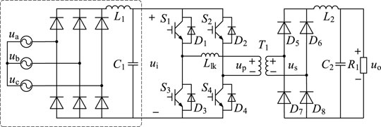
FIGURE 1. Topology structure of the system.
The DC-DC high-power switching converter adopts the phase-shifted PWM control. The two switches of the same bridge arm are complementary. The staggered angle when the diagonal switches between the two bridge arms are conducted is named as the phase-shifted angle. It determines the on-duty ratio of the switches. Figure 2 shows a waveform diagram of the working principle of the phase-shifted full-bridge converter ignoring the dead time (Shah and Bhattacharya, 2019); t0∼t8 is one cycle of the switch tube.
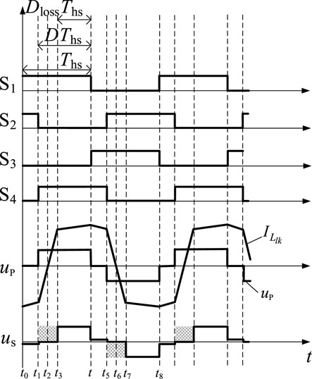
FIGURE 2. Waveform diagram of the working principle of phase-shifted full-bridge converter.
In this figure, up is the primary side voltage and its duty ratio is D. us is the secondary side voltage. Since the resonance inductance and the junction capacitance of the switch tube form series resonance in t1∼t3 and t5∼t7, the transformer is in the short circuit state. It results in the loss of the secondary side voltage duty ratio, the shaded part in the figure, which is set as Dloss; then the effective duty ratio Deff of the secondary side of the transformer is
Since the full-bridge circuit generally works in the deep continuous state, Deff can be simplified as
where fs is the switching frequency of the converter and IL2 is the filtering inductance’s current.
In this study, the isolated DC-DC converter adopts constant voltage control. First, the reference value of the output voltage of the converter Uoref forms a voltage deviation signal with sampling value uo. Then the duty ratio of the primary side of the transformer is obtained by the PI controller. Due to the loss of the duty ratio of the secondary side voltage of Eq. 2, the duty ratio of the secondary side is finally obtained by Eq. 1. The transmission power of the converter is adjusted by changing the duty ratio, as shown in Figure 5.
3 Voltage Response Improvement Method Based on the RBFNN
The phase-shifted full-bridge DC-DC converter adopts a constant voltage control. Because of the nonlinearity and complexity of the converter, a single PI regulation control cannot meet the requirements of regulating speed and other control performance in industrial applications such as automotive electrophoretic painting. Radial basis function neural networks are a commonly used type of artificial neural network for function approximation problems. Radial basis function neural networks are distinguished from other neural networks owing to their universal approximation and faster learning speed. An RBFNN is a type of feedforward neural network composed of three layers, namely, the input layer, the hidden layer, and the output layer. Each of these layers has different tasks. Therefore, the model based on the RBFNN is adopted in this section. According to the detected output voltage deviation and load current value, the compensation amount of the converter duty ratio is directly given. It helps the PI controller to speed up the voltage regulation, reduce the voltage sag or rise amplitude, and finally realize the stability of output voltage.
The RBFNN model can approach any nonlinear mapping by learning without understanding the specific relationship between input and output variables. The model can summarize the mapping law among output voltage, load current, and their change rate from the experimental data. It also has the generalization ability for nonlinear complex problems (Seshagiri and Khalil 2000; Weatherspoon et al., 2007; Fei and Lu, 2018; Liu et al., 2020).
The operation of the model applied to the switching converter is divided into two stages. In the early learning stage, the structural parameters such as the weight matrix of the RBF neural network are trained by MATLAB software and a large number of data samples (Vlatkovic et al., 1992; Wu et al., 2021; Zhang et al., 2017). The structural parameters are searched by the look-up table method, and the compensation amount of the duty ratio is calculated during the experiment. The experimental model has few nodes, so the amount of data stored is small. A large number of data calculation and processing links are set in the early learning stage, which ensures the rapidity of the online stage (Dong et al., 2021; Rojas-Dueñas et al., 2021; Rubio-Solis and Panoutsos, 2015). The aforementioned method not only avoids the repeated adjustment of PI control parameters in the experiment but also alleviates the mutation degree of output voltage when the load changes and shortens the recovery time of system voltage. The overall model design process is shown in Figure 3.
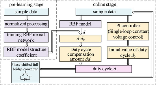
FIGURE 3. Flowchart of the model design.
3.1 Sample Selection and Pretreatment
The model of the RBFNN is based on the sample data. Data integrity is an important step in the data training process. It is of great importance for safe and efficient operation in the proposed control method. If there is inappropriate information present or noisy and unreliable data, then knowledge discovery becomes very difficult during the training process. Data preparation and filtering steps can take a considerable amount of processing time, but once training is done, the data become more reliable and robust results are achieved (Hu et al., 2020; Hu et al., 2021). The sample data were obtained by the experimental test in this study. The operation data under various typical conditions were obtained by the pretest. The neural network model has good generalization ability for interpolated sample points in the sample set, whereas it has poor generalization ability for extended sample points. Therefore, to make the sample data basically cover the whole range of practical applications, the selection of sample points should be typical and representative. Multiple groups of measured data can be collected, most of which are used for training networks and a few of which are used for inspection. Each group of data is composed of input and output, respectively. In this study, it is the load current value, voltage deviation, and corresponding duty ratio. All kinds of data set their corresponding variation range according to the actual system.
Eq. 3 is used to preprocess all kinds of sample data. Normalization can accelerate the convergence of network training.
3.2 Neural Network Training Process
The RBFNN is a feedforward neural network which uses the weighted sum of basic functions to approximate unknown functions. The RBFNN has a three-layer network structure: input layer, hidden layer, and output layer, as shown in Figure 4. There are two neurons in the input layer, which are the steady-state deviation of load current and voltage, respectively. There is one neuron in the output layer, which is the duty ratio compensation. The number of neurons in the middle hidden layer is set as m, and the basis function of the hidden layer adopts the Gaussian function.
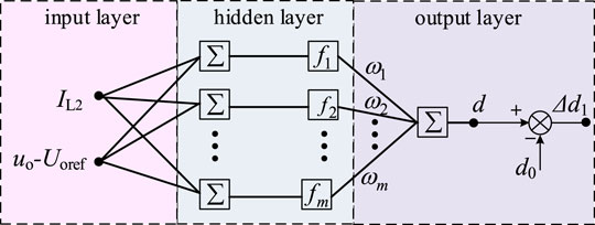
FIGURE 4. RBFNN structure.
The input of the input layer is X = [x1,x2], and the output is y. The radial basis vector of the hidden layer of the RBF network is F = [f1,f2,…,fi,…,fm]T, and the action function fi of the i-th neuron in the hidden layer is expressed as
where Ci is the center of the i-th basis function, which has the same dimension as X; σi is the width of the i-th basis function.
The input layer realizes the nonlinear mapping from xi to fi, the output layer realizes the linear mapping from fi to y. The output y is expressed as
where ωi is the connection weight between the i-th neuron of the hidden layer and the output y.
In the early learning stage, the data samples are imported into MATLAB software. The toolbox completes the training process of the RBFNN, and outputs the structural parameters of the RBF model, including the center value C = [c1,c2,…,ci,…,cm] of each basis function, the width of each basis function σ = [σ1,σ2,…,σi,…,σm], and the connection weight between the hidden layer and the output layer ω = [ω1, ω2,…,ωi,…,ωm].
The RBFNN model and its structural parameters are deployed in the DSP controller of the experimental system. The steady-state deviation between the sampled load current and voltage is directly calculated by the RBF model to obtain the compensation amount of duty ratio Δd1. The initial duty ratio value d0 and the duty ratio compensation amount Δd1 are transmitted to the duty ratio calculation module to obtain the updated switch duty ratio d, which directly controls the isolated DC-DC converter in the main circuit. Then, the PI controller in the control loop continues to regulate the output voltage until the voltage reference value is less than the set minimum error value. Finally, the output voltage is controlled to be stable. The RBFNN model is used to help the PI controller to speed up the voltage regulation and improve voltage response.
3.3 Mathematical Modeling and Stability Analysis
When the PI control is adopted in the DC converter, the circuit equation of the voltage loop can be expressed as
where Uref is the voltage reference value, and kp and ki are the proportional and integral coefficients, respectively.
The transfer function of the converter from the duty cycle to the output voltage is expressed as
The transfer function of the converter from input voltage to the output voltage is expressed as
In addition, since the input layer neurons controlled by the RBFNN are the steady-state deviation between load current and voltage, respectively, and the output is the duty cycle compensation, the transfer function can be expressed as
where kRBF is the simplification coefficient of RBFNN, and R1 is the load resistance.
Then the control model diagram can be shown in Figure 5.
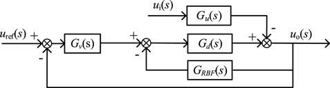
FIGURE 5. Control model diagram with the proposed RBFNN strategy.
The loop gain T from the output voltage to the reference voltage can be obtained from Figure 8, which is expressed as
The Bode diagram of the loop gain function of the converter under voltage control is drawn, as shown in Figure 6, where ωc1 and ωc2 are the cutoff frequency in the two control methods, γ1 and γ2 are the corresponding phase angle at the cutoff frequency. The closed-loop stability of the system with and without compensation is indirectly analyzed by analyzing the amplitude-frequency characteristics and phase-frequency characteristics of loop gain function GT. It can be seen that the amplitude margin with and without compensation is 54 dB, while the phase angle margin increases from 34.2° to 43.2° with compensation. The stability margin of the system has been improved to a certain extent and has good anti-interference ability. The shear frequency of the system with compensation is added at the same time ωc from 4.77 to 5.8 kHz, and the response speed of the closed-loop system is improved.
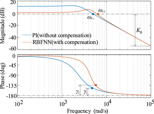
FIGURE 6. Bode diagram of the DC converter closed loop gain.
4 Voltage Ripple Suppression Method
When the AC power grid supplies power to the DC load, the DC bus voltage output by the uncontrolled rectifier circuit has six-pulse components. The output voltage of the DC converter also has six-pulse components. The ripple of the output voltage can be reduced by adding capacitors and inductors. Considering the influence of the cost, this study presents a method to eliminate the ripple from the control. The calculation shows that the variation period of the pulsation component is Tm = 3.3 ms. The DC converter adopts single loop constant voltage control. Although the PI controller can adjust about 49 times in a 3.3 ms change cycle to suppress the pulsation, the duty ratio calculated from the previous sampling cycle is not applicable to the next sampling cycle. As a result, the PI controller adjusts repeatedly in the pulsation cycle, and the suppression effect of pulsation is very little.
Since the ripple component of the load voltage is a periodic voltage ripple, a delay-free voltage ripple suppression method is proposed in this study. In addition to calculating the required duty ratio compensation amount in each sampling time in the last pulsation cycle, this strategy controls the delay time to make the duty ratio compensation amount act on the corresponding sampling time in the next pulsation cycle, so as to better suppress the voltage ripple.
Delay compensation Δτ is the difference between pulsation period Tm and delay time τ, which is shown in Eq. 11. The duty ratio compensation obtained from the previous pulsation cycle directly acts on the next pulsation cycle. The delay time τ consists of three parts, which are the delay time τ1 caused by the sampling, the time τ2 used by the controller, and the hardware delay time τ3.
In the steady state, the compensation amount of voltage ripple needs to be determined according to the actual output voltage u0 of DC converter Δd2. The greater the load, the higher the pulsation component of the voltage. Thus, the compensation amount for voltage ripple improvement Δd2 shall be inverse to the output voltage ripple of the converter, which is a function of load, output voltage, and duty ratio. The specific function is as follows:
where d0 is the steady-state value of the duty ratio output by the controller, UB is the selected ripple compensation reference value, and dN is the duty ratio of the DC converter corresponding to the rated load. The value range of Δd2/kb is −0.01∼0.01. Item (1-u0/UB)| 1-u0/UB | mainly reflects the direct improvement of voltage ripple. Item (dN/d0)2 is introduced to reduce the influence of the nonlinear relationship between the duty ratio and load change on the compensation effect. kb is the compensation coefficient, which is generally 1. It can be increased or decreased according to the actual improvement effect in different application scenarios. Figure 7 is a control block diagram of the proposed strategy. The improvement strategy is proposed for the steady-state condition. To prevent the compensation caused by the sudden voltage change under the transient conditions from being too large or too small, amplitude limiting is carried out in the control. The limiting condition is (Δd2/kb)∈[−0.01, 0.01].
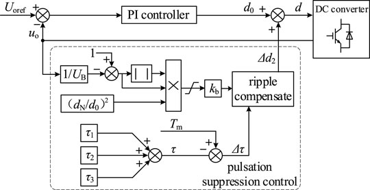
FIGURE 7. Control block diagram of voltage ripple suppression.
According to Eq. 11, the total delay time τ measured by the experiment is three sampling times, that is, τ = 0.199 ms, and the delay compensation Δτ = 3.067 ms. UB is selected to be 200 V.
Figure 8 is a schematic diagram of the improvement effect of voltage ripple in a ripple period of 3.3 ms. Since the PI controller has been calculated and adjusted 49 times in this cycle, the figure also has 49 adjustment points accordingly.

FIGURE 8. Schematic diagram of the suppression effect of the voltage ripple.
In conclusion, in the proposed delay-free voltage ripple suppression method, the design of duty ratio compensation and delay time to suppress the pulsation component can effectively weaken the pulsation component and improve the output voltage quality of the DC converter.
5 Experimental Verification
5.1 Overview of the Experimental Platform
To verify the effectiveness and superiority of the proposed control method, an experimental platform is built as shown in Figure 9.
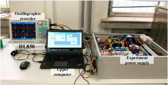
FIGURE 9. Experimental system diagram.
The system is composed of the main circuit, DSP controller, host computer, and wave recorder. The topology of the experimental circuit is shown in Figure 1. The control methods proposed in this study are deployed in the DSP controller (TMS320F28335), and the experimental waveform is measured by wave recorder DL850. The control parameters and experimental circuit device parameters of the experimental system are listed in Table 1.

TABLE 1. Control parameters and device parameters of the experimental system.
5.2 Experimental Verification and Analysis
Figure 10 shows the experimental waveform under sudden load, with a total of 10s of data recorded. uabc and iabc are the input voltage and current of a three-phase bridge uncontrolled rectifier, respectively. ui is the output voltage of a three-phase uncontrolled rectifier. uo and io are the output voltage and output current of the isolated DC-DC converter, that is, load voltage and current, respectively. Figure 10 shows the experimental waveforms of the complete duration and partial amplification of the system in the case of sudden load changes, and the enlarged part has been outlined in dotted circles in the figure. In the initial time, ui is 537 V, the voltage uo at both ends of the load is 200 V, the resistance R1 is 10 kΩ, and the system is in a no-load state. In about 4.8 s, the resistance R1 decreases from 10 kΩ to 8 Ω, that is, the system enters the load state from no-load. The following information can be concluded from the experimental waveforms in Figure 10. At the moment of load increase, there is a peak in the output current due to the decrease of R1. The output current increases from 0.05 to 25 A. The output voltage has a serious voltage sag, the sag amplitude reaches 80% to 160 V, and the sag lasts for more than 1s. These effects are caused by the slow PI regulation speed. The system has no time to respond. After the load increases and enters the steady state, due to the limited voltage stabilizing effect of the capacitor, the fluctuation amplitude of the voltage ui of the DC bus increases, and the peak value of the ripple reaches 100 V. Finally, voltage u0 at both terminals of the load also has a large six-pulse fluctuation component and the ripple amplitude is around 42 V.
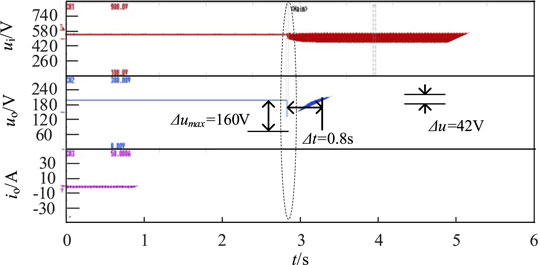
FIGURE 10. Experimental waveforms of the system under the load mutation.
In this study, the voltage response improvement method based on RBF is adopted, and the process is as follows. In the early learning stage, 420 groups of measured data are collected by the experimental test. All the operation conditions are taken into account when collecting the data. 400 groups of sample data are used for training the network and 20 groups of measured data are used as test samples. Each group is composed of the load current value, voltage deviation, and corresponding duty ratio. To save the computing time in the actual controller using the RBFNN method, the obtained data are processed offline in Matlab and applied to the actual controller by using a lookup table. The control requirements can be met in this way. The output voltage is maintained at 200 V, the range of voltage deviation is −160 V∼+160 V, the variation range of the load current value is 0∼25 A, and the variation range of the duty ratio is 0∼1. The larger the selection range of data samples, the better the adaptability and effect of the model for other load jump situations. After consulting a large number of literature and repeated experiments, it is finally determined that the number of neurons in RBF hidden layer m is 20. Figure 11 shows the fitting relationship between input and output in the network after training by MATLAB and a large number of data samples. The trained network is tested with 20 groups of data, and the average relative error between the output value and the actual value is 0.61%. It can be seen that the trained RBFNN model has a small error and excellent performance. The weight matrix and other structural parameters of the derived RBFNN are shown in Table A1.
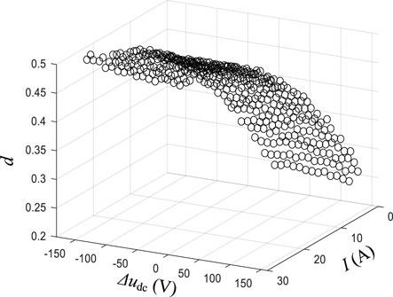
FIGURE 11. Actual duty ratio of the training samples and the fit duty ratio of the test samples.
After the completion of the preliminary learning stage, the structural parameters such as the weight matrix of RBFNN have been uploaded to the DSP controller. Figure 12 shows the experimental waveform when the RBF-based voltage response improvement control strategy is adopted. The working condition is the same as Figure 10. The following information can be concluded from the experimental waveform in the figure. At the moment of the sudden increase of load, the output voltage suddenly decreases from 80% to 15%, and the duration of sag is only 1∼2 ms. This is mainly because the RBFNN directly and quickly supplies the duty ratio compensation of the switching converter, which greatly shortens the time required by the PI controller to adjust the output voltage. It is verified that the control strategy can effectively improve the voltage mutation problem in the case of load mutation. However, the large voltage ripple at both ends of the load has not been improved.
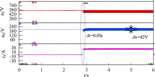
FIGURE 12. Experimental waveforms for the proposed RBFNN control strategy.
To further eliminate the ripple of load voltage, the delay-free voltage ripple suppression method is added for the experiment. The working condition is the same as that described earlier, and the experimental waveform is shown in Figure 13. After the sudden increase of load, the ripple of the output voltage is reduced from 42 to 9 V. The ripple amplitude is reduced by 75%. The delay time in the control strategy is properly controlled, so the duty ratio can be adjusted according to the change of bus voltage, which effectively reduces the ripple of output voltage.
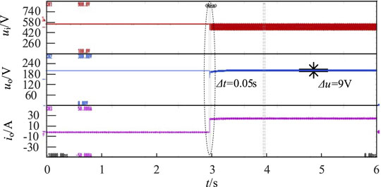
FIGURE 13. Experimental waveforms for the proposed control strategy.
In conclusion, the voltage response improvement method based on RBF can effectively solve the problem of voltage mutation when the load changes suddenly. The addition of the delay-free voltage ripple suppression method eliminates the ripple of load voltage. The combination of transient voltage response improvement strategy and steady-state voltage ripple improvement strategy suppresses the fluctuation of output voltage and greatly improves the voltage quality of load.
6 Conclusion
In order to improve the output voltage quality of isolated DC-DC converter, a voltage response improvement method based on RBF and a delay-free voltage ripple suppression method are proposed in this study. The influence of the voltage response improvement strategy on the system stability is analyzed. The effectiveness of the proposed control strategy is verified by experiments. The conclusions are as follows:
(1) The RBF model proposed in this study can improve the PI controller to speed up the voltage regulation and improve the voltage response. It is an effective control method.
(2) The designed delay-free voltage ripple suppression method can effectively reduce the ripple component of the DC output voltage of the isolated DC-DC converter caused by a pre-stage uncontrolled rectifier circuit. It can also reduce the economic cost caused by the external capacitance and inductance. The proposed control strategy has a reference significant for the control of converters with pulsating source characteristics at the source end.
Data Availability Statement
The original contributions presented in the study are included in the article/Supplementary Material, further inquiries can be directed to the corresponding author.
Author Contributions
ML and KW conceived the idea for this survey paper. ZZ, HL, WZ and JK were responsible for the main writing of the paper, while JM was responsible for revising the manuscript. All authors contributed to the article and approved the submitted version.
Funding
This study received funding from the State Grid Corporation of China (5419-202114240A-0-0-00). The supported project is Research on key technologies of energy storage allocation in renewable energy power station for both renewable energy accommodation level increase and active support of power grid.
Conflict of Interest
Authors ML, ZZ, HL,WZ and JK were employed by the company State Grid Jibei Zhangjiakou Wind and Solar Energy Storage and Transportation New Energy Co., Ltd. Author KW was employed by the company North China Electric Power Research Institute Co., Ltd.
The remaining authors declare that the research was conducted in the absence of any commercial or financial relationships that could be construed as a potential conflict of interest.
Publisher’s Note
All claims expressed in this article are solely those of the authors and do not necessarily represent those of their affiliated organizations, or those of the publisher, the editors, and the reviewers. Any product that may be evaluated in this article, or claim that may be made by its manufacturer, is not guaranteed or endorsed by the publisher.
References
Abeywardana, D. B. W., Hredzak, B., and Agelidis, V. G. (2016). An Input Current Feedback Method to Mitigate the DC-Side Low-Frequency Ripple Current in a Single-phase Boost Inverter. IEEE Trans. Power Electron. 31 (6), 4594–4603. doi:10.1109/TPEL.2015.2473170
Brunoro, M., and Vieira, J. L. F. (1999). A High-Performance ZVS Full-Bridge DC-DC 0-50-V/0-10-A Power Supply with Phase-Shift Control. IEEE Trans. Power Electron. 14 (3), 495–505. doi:10.1109/63.761693
Dong, W., Li, S., Fu, X., Li, Z., Fairbank, M., and Gao, Y. (2021). Control of a Buck DC/DC Converter Using Approximate Dynamic Programming and Artificial Neural Networks. IEEE Trans. Circuits Syst. 68 (4), 1760–1768. doi:10.1109/TCSI.2021.3053468
Fei, J., and Lu, C. (2018). Adaptive Sliding Mode Control of Dynamic Systems Using Double Loop Recurrent Neural Network Structure. IEEE Trans. Neural Netw. Learn. Syst. 29 (4), 1275–1286. doi:10.1109/TNNLS.2017.2672998
Gao, M., Wang, D., Li, Y., and Yuan, T. (2018). Fixed Frequency Pulse-Width Modulation Based Integrated Sliding Mode Controller for Phase-Shifted Full-Bridge Converters. IEEE Acces 6, 2181–2192. doi:10.1109/ACCESS.2017.2782225
Goyal, V. K., and Shukla, A. (2021). Isolated DC-DC Boost Converter for Wide Input Voltage Range and Wide Load Range Applications. IEEE Trans. Ind. Electron. 68 (10), 9527–9539. doi:10.1109/TIE.2020.3029479
Hu, X., Zhang, H., Ma, D., and Wang, R. (2021). A tnGAN-Based Leak Detection Method for Pipeline Network Considering Incomplete Sensor Data. IEEE Trans. Instrum. Meas. 70, 1–10. doi:10.1109/TIM.2020.3045843
Hu, X., Zhang, H., Ma, D., and Wang, R. (2021). “Hierarchical Pressure Data Recovery for Pipeline Network via Generative Adversarial Networks,” in IEEE Transactions on Automation Science and Engineering, early access. doi:10.1109/tase.2021.3069003
Liu, H., Zhao, Y., Shurafa, M. A., Chen, J., Wu, J., and Cheng, Y. (2021). “A Novel PID Control Strategy Based on PSO-BP Neural Network for Phase-Shifted Full-Bridge Current-Doubler Synchronous Rectifying Converter,” in 2021 IEEE 4th Advanced Information Management, Communicates, Electronic and Automation Control Conference (IMCEC), 1241–1245. doi:10.1109/IMCEC51613.2021.9482183
Liu, Q., Liang, T., and Dinavahi, V. (2020). Real-Time Hierarchical Neural Network Based Fault Detection and Isolation for High-Speed Railway System Under Hybrid AC/DC Grid. IEEE Trans. Power Deliv. 35 (6), 1. doi:10.1109/TPWRD.2020.3022750
Lo, Y.-K., Lin, C.-Y., Hsieh, M.-T., and Lin, C.-Y. (2011). Phase-Shifted Full-Bridge Series-Resonant DC-DC Converters for Wide Load Variations. IEEE Trans. Ind. Electron. 58 (6), 2572–2575. doi:10.1109/TIE.2010.2058076
Mallik, A., and Khaligh, A. (2017). Variable-Switching-Frequency State-Feedback Control of a Phase-Shifted Full-Bridge DC/DC Converter. IEEE Trans. Power Electron. 32 (8), 6523–6531. doi:10.1109/TPEL.2016.2616033
Matsumori, H., Kosaka, T., Sekido, K., Kim, K., Egawa, T., and Matsui, N. (2019). “Isolated DC-DC Converter Utilizing GaN Power Device for Automotive Application,” in 2019 IEEE Applied Power Electronics Conference and Exposition (APEC), 1704–1709. doi:10.1109/APEC.2019.8722097
Rojas-Duenas, G., Riba, J.-R., and Moreno-Eguilaz, M. (2021). Black-Box Modeling of DC-DC Converters Based on Wavelet Convolutional Neural Networks. IEEE Trans. Instrum. Meas. 70, 1–9. doi:10.1109/TIM.2021.3098377
Rubio-Solis, A., and Panoutsos, G. (2015). Interval Type-2 Radial Basis Function Neural Network: A Modeling Framework. IEEE Trans. Fuzzy Syst. 23 (2), 457–473. doi:10.1109/TFUZZ.2014.2315656
Saleh, B., Teirelbar, A., and Wasfi, A. (2020). “A DC/DC Buck-Boost Converter Control Using Sliding Surface Mode Controller and Adaptive PID Controller,” in 2020 22nd European Conference on Power Electronics and Applications (EPE'20 ECCE Europe), 8. doi:10.23919/EPE20ECCEEurope43536.2020.9215853
Seshagiri, S., and Khalil, H. K. (2000). Output Feedback Control of Nonlinear Systems Using RBF Neural Networks. IEEE Trans. Neural Netw. 11 (1), 69–79. doi:10.1109/72.822511
Shah, S. S., and Bhattacharya, S. (2019). A Simple Unified Model for Generic Operation of Dual Active Bridge Converter. IEEE Trans. Ind. Electron. 66 (5), 3486–3495. doi:10.1109/TIE.2018.2850012
Shan, Z., Jatskevich, J., Iu, H. H.-C., and Fernando, T. (2018). Simplified Load-Feedforward Control Design for Dual-Active-Bridge Converters with Current-Mode Modulation. IEEE J. Emerg. Sel. Top. Power Electron. 6 (4), 2073–2085. doi:10.1109/JESTPE.2018.2797998
Török, L., and Munk-Nielsen, S. (2011). “Digital Fuzzy Logic and PI Control of Phase-Shifted Full-Bridge Current-Doubler Converter,” in 2011 IEEE 33rd International Telecommunications Energy Conference (INTELEC), 1–7. doi:10.1109/INTLEC.2011.6099833
Vlatkovic, V., Sabate, J. A., Ridley, R. B., Lee, F. C., and Cho, B. H. (1992). Small-signal Analysis of the Phase-Shifted PWM Converter. IEEE Trans. Power Electron. 7 (1), 128–135. doi:10.1109/63.124585
Weatherspoon, M. H., Martinez, H. A., Langoni, D., and Foo, S. Y. (2007). Small-signal Modeling of Microwave MESFETs Using RBF-ANNs. IEEE Trans. Instrum. Meas. 56 (5), 2067–2072. doi:10.1109/tim.2007.895585
Wu, H., Mu, T., Ge, H., and Xing, Y. (2016). Full-Range Soft-Switching-Isolated Buck-Boost Converters with Integrated Interleaved Boost Converter and Phase-Shifted Control. IEEE Trans. Power Electron. 31 (2), 987–999. doi:10.1109/TPEL.2015.2425956
Wu, J., Li, X., Li, X., and Xu, G. (2021). “Modeling of Non-ideal Buck Converter and Design of Compensation Network,” in 2021 IEEE 5th Information Technology, Networking, Electronic and Automation Control Conference (ITNEC), 429–435. doi:10.1109/ITNEC52019.2021.9587048
Xiao, W., Lei, L., Chen, Q., Zhang, L., and Quan, S. (2017). “Sliding Mode Control of a Phase Shifted Full Bridge DC/DC Converter,” in 2017 32nd Youth Academic Annual Conference of Chinese Association of Automation (YAC), 138–142. doi:10.1109/YAC.2017.7967393
Zhang, H., Tong, X., and Yin, J. (2017). “Optimal Triple-Phase-Shift Controller Design of Isolated Bidirectional DC-DC Converter Based on Ant colony Algorithm and BP Neural Network,” in IECON 2017 - 43rd Annual Conference of the IEEE Industrial Electronics Society, 8802–8807. doi:10.1109/IECON.2017.8217547
Appendix
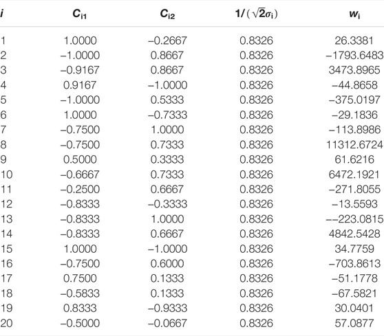
TABLE A1. Neural network structure parameter.
Keywords: DC-DC converter, voltage response, radial basis function (RBF) neural network, ripple suppression, voltage quality
Citation: Li M, Wang K, Zhao Z, Liu H, Zhang W, Kou J and Meng J (2022) Control Method for Improving Voltage Response and Ripple of Isolated DC-DC Converter. Front. Energy Res. 10:858601. doi: 10.3389/fenrg.2022.858601
Received: 20 January 2022; Accepted: 21 February 2022;
Published: 07 April 2022.
Edited by:
Jorge Rodas, Universidad Nacional de Asunción, ParaguayReviewed by:
Dazhong Ma, Northeastern University, ChinaJunmin Jiang, Southern University of Science and Technology, China
Copyright © 2022 Li, Wang, Zhao, Liu, Zhang, Kou and Meng. This is an open-access article distributed under the terms of the Creative Commons Attribution License (CC BY). The use, distribution or reproduction in other forums is permitted, provided the original author(s) and the copyright owner(s) are credited and that the original publication in this journal is cited, in accordance with accepted academic practice. No use, distribution or reproduction is permitted which does not comply with these terms.
*Correspondence: Jianhui Meng, bWVuZ2ppYW5odWkyMDA4QDE2My5jb20=